

Page 1
CONNECTORS
- 238 -
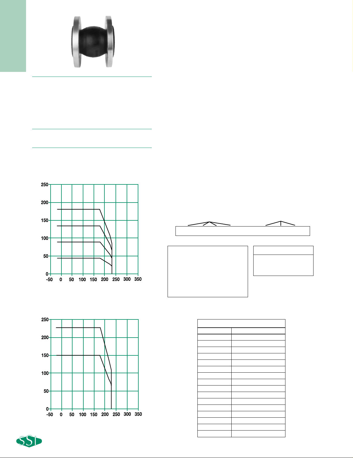
SERIES ASM
NEOPRENE/EPMD FLANGED
SINGLE SPHERE CONNECTOR
Pressures to 225 PSIG (15.51 barg)
Temperatures to 230ºF (110ºC)
● For connection pipes and equipment where
flanged ends are preferred
● Flat faced flanged single sphere connectors
● Easy to install floating flanges allow variable
pressure, temperature and movement
● Increased acoustic resistance, dampens
hydraulic surge and shock
● Accommodates thermal movement and
misalignment
● Four way greater movement provides high level
of installation flexibility
● Precision molded synthetic rubber reinforced
with nylon cord
● Horizontal or vertical mounting
APPLICA TIONS
● Process Industry
● Weak Acids
● Alkalies
● Compressed Air
● Pulp & Paper
MODELS
● ASM - Flanged Connection
O
PTIONS
● Control Rods
0 6 0 0 - A S M
12345678
Inlet Size
Model
Dash
Series ASM Ordering Code
Dash - Position 5
Model - Position 6 -8
ASM - Single Sphere,
FLG, CI, Neoprene
Inlet Size* - Position 1 - 4
0100 - 1" 0600 - 6"
0125 - 11⁄
4" 0800 - 8"
0150 - 1
1
⁄
2" 1000 - 10"
0200 - 2" 1200 - 12"
0250 - 2
1
⁄
2" 1400 - 14"
0300 - 3" 1600 - 16"
0400 - 4" 1800 - 18"
0500 - 5" 2000 - 20"
ASM
Size Part Number
1 0100-ASMROD
11⁄4 0125-ASMROD
11⁄2 0150-ASMROD
2 0200-ASMROD
21⁄2 0250-ASMROD
3 0300-ASMROD
4 0400-ASMROD
5 0500-ASMROD
6 0600-ASMROD
8 0800-ASMROD
10 1000-ASMROD
12 1200-ASMROD
14 1400-ASMROD
16 1600-ASMROD
18 1800-ASMROD
20 2000-ASMROD
Other sizes available. Consult factory.
Part Numbers for Ordering Single
Sphere Connector Control Rods
● Oil & Gas
● Water & Waste
● Pump suction & discharge
● Sea water
● Chemical lines
PRESSURE/TEMPERATURE RATINGS
WITHOUT CONTROL RODS
PRESSURE/TEMPERATURE RATINGS
WITH CONTROL RODS
SIZE: 1” to 4”
SIZE: 5” to 10”
SIZE: 12” to 14”
Pressure (psi)
SIZE: 16” to 20”
Temperature (F)
SIZE: 1” to 12”
SIZE: 14” to 20”
Pressure (psi)
Temperature (F)
Page 2

CONNECTORS
- 239 -
Connections: 1" to 20" Flanged
Other sizes available. Consult factory.
Dimensions are subject to change. Consult
factory for certified drawings when required.
SERIES ASM
NEOPRENE/EPMD FLANGED
SINGLE SPHERE CONNECTOR
SPECIFICATION
Single Sphere Connector body material shall be neoprene cover and
tube elastomer with nylon cord fabric reinforcement. The single sphere
connector will have Carbon Steel, Zinc Plated flanges and a hard
steel wire frame. The twin sphere connector shall be SSI ASM Series.
M
ATERIALS OF CONSTRUCTION
Body ......................................................................Neoprene
Reinforcing Fabric ......................................Nylon Cord Fabric
Wire ..............................................................Hard Steel Wire
Floating Flanges..............Carbon Steel Zinc Plated RST 37-2
Allowable Movement Weight
Axial Axial Lateral Angular Connector With
Size A Compression Extension Deflection Deflection B C Only Rods
1 6 3/4 15/32 9/16 19/32 117⁄
32 2
15
⁄
16 5 10
(25) (152) (19) (12) (14) (15) (39) (75) (2.3) (4.7)
11⁄
4 6 3/4 15/32 9/16 19/32 1
17
⁄
32 2
15
⁄
16 7 10
(32) (152) (19) (12) (14) 15) (39) (75) (3.2) (4.7)
11⁄
2 6 3/4 15/32 9/16 19/32 1
17
⁄
32 2
15
⁄
16 8 12
(38) (152) (19) (12) (14) (15) (39) (75) (3.6) (5.4)
2 6 3/4 15/32 9/16 19/32 129⁄
32 3
3
⁄
8 11 15
(51) (152) (19) (12) (14) (15) (48) (86) (5.0) (7.0)
21⁄
2 6 3/4 15/32 9/16 19/32 2
15
⁄
32 4
1
⁄
8 11 19
(64) (152) (19) (12) (14) (15) (63) (105) (5.0) (8.7)
3 6 3/4 15/32 9/16 19/32 27⁄
8 4
21
⁄
32 13 23
(76) (152) (19) (12) (14) (15) (73) (118) (5.9) (10.4)
461⁄
8 3/4 15/32 9/16 19/32 3
15
⁄
16 5
27
⁄
32 17 25
(102) (156) (19) (12) (14) (15) 100) (148) (7.7) (11.4)
561⁄
8 3/4 15/32 9/16 19/32 5 7
1
⁄
64 21 30
(127) (156) (19) (12) (14) (15) (127) (178) (9.5) (13.6)
661⁄8 3/4 15/32 9/16 19/32 525⁄32 89⁄32 25 37
(152) (156) (19) (12) (14) (15) (147) (210) (11.3) (16.8)
861⁄8 1 15/32 7/8 19/32 727⁄32 101⁄4 37 53
(203) (156) (25) (12) (22) (15) (199) (260) (16.8) (24.0)
10 8 1 5/8 7/8 19/32 93⁄4 1211⁄16 58 82
(254) (203) (25) (16) (22) (15) (248) (322) (26.3) (37.2)
12 8 1 5/8 7/8 19/32 1121⁄32 149⁄16 80 109
(305) (203) (25) (16) (22) (15) (296) (370) (36.3) (49.4)
14 8 1 5/8 7/8 19/32 137⁄32 161⁄4 101 138
(356) (203) (25) (16) (22) (15) (336) (413) (45.8) (62.6)
16 8 1 5/8 7/8 19/32 155⁄32 189⁄32 127 176
(406) (203) (25) (16) (22) (15) (385) (464) (57.6) (79.8)
18 8 1 5/8 7/8 19/32 175⁄16 205⁄8 136 183
(457) (203) (25) (16) (22) (15) (440) (524) (61.7) (83.0)
20 8 1 5/8 7/8 19/32 199⁄32 229⁄16 158 212
(508) (203) (25) (16) (22) (15) (490) (573) (71.7) (96.1)
DIMENSIONS inches (mm) AND WEIGHTS pounds (kg)
Installation Note:
For correct Installation & Maintenance
instructions
A
C
B
Burst Pressure 850 PSIG
see page 244
C
B
A
 Loading...