

Page 1

12950 W.Eight Mile Road • Oak Park,MI 48237-3288 • 248/399-8000 • FAX:248/399-7246 • www.tr erice.com
1/1/2001
9
Temperature Regulator 91000 Series
“The Self-Op”
Models
91000 (Non-Indicating)
91400 (Indicating)
91600 (Fail-Safe)
Power Requirements
Fully self-contained – no external
power required.
Dial Thermometer
31/2" dial, stainless steel case,
swivel and angle adjustment
(Model 91400 only)
Housing
Die cast aluminum, epoxy
powder coated blue finish
Set Point Scale
Integral to housing
Bellows
High pressure brass, corrosion
resistant, tin plated finish
Adjustment Screw
Brass
Adjustment Screw Bushing
Lubricant impregnated sintered
bronze
Range Adjustment Spring
Cadmium plated
Overrange Protection
Upper range limit +100°F for
temporary situations (not
available for Model 91600)
Approximate Shipping
Weight
Actuator –
91000: 6.0 lbs [2.70 kg]
91400: 6.6 lbs [2.97 kg]
91600: 9.5 lbs [4.32 kg]
Valve –
See Valve Selection tables.
Sample Order Number: 91400CR0608B01-A26
91400 C R06 08 B01 A26
Model Level of Assembly Range Capillary Length Thermal System Thermowell – Valve
91000 Non-Indicating A Actuator only See Standard 08 8 Feet See Thermal W01 Brass For 91000/91400
91400 Indicating C Complete Available Ranges 12 12 Feet System Selection W02 Steel see pages 15-22
91600 Fail-Safe Regulator (page 11) 16 16 Feet (page 12) W04 316SS For 91600
20 20 Feet Omit if see page 23
none Omit if Actuator Only
How to Order
Specifications
The Series 91000 Self-Operating Temperature
Regulator is the preferred choice of original equipment
manufacturers, mechanical contractors and specifying
engineers. This regulator requires no external power
source and is ideal for regulating the temperature of
tanks, process streams and various industrial
equipment. The actuator is noted for its rugged, die cast
aluminum housing. The Model 91400 is furnished with
an adjustable dial thermometer to allow the operator to
verify the process temperature. The Model 91600 FailSafe Actuator is designed to cause the valve to fail in
the safe control position (open in a cooling application,
closed in a heating application) should accidental
damage to the thermal system occur, resulting in loss of
the pressure charge.
For optimal performance,the service conditions (medium,
flow, temperature, inlet and outlet pressures) of the
application must be considered when selecting a valve.
Please refer to the Valve Selection Section of this catalog.
For applications where the process media may be corrosive
or contained under pressure,the use of a thermowell is
required to prevent damage to the regulator bulb and
facilitate its removal from the process. Improper
application may cause failure of the valve, resulting in
possible personal injury or property damage.
Self-Operating
Design
Indicating,
Non-Indicating
or Safety
Models
Available
Heavy Duty
Die Cast
Aluminum
Housing
1
/2
" thru 6"
Val ve Si z e s
91400 pictured
Other: Specify Length
in Feet (52' maximum)
Temperature Regulators
Page 2
12950 W.Eight Mile Road • Oak Park,MI 48237-3288 • 248/399-8000 • FAX:248/399-7246 • www.tr erice .c om
1/1/2001
1010
Temperature Regulator 91000 Series
“The Trerice Self-Op ”
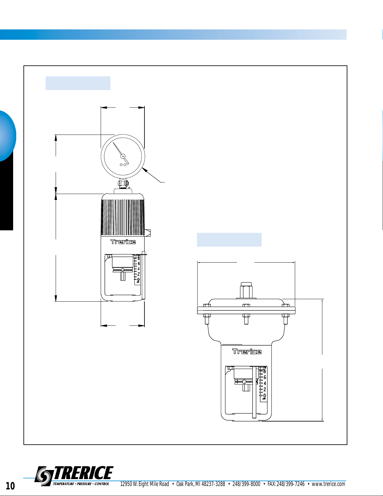
All dimensions are nominal.
Dimensions in [ ] are in millimeters.
DIAL THERMOMETER
(MODEL 91400 ONLY)
Ø
3.67
[93]
4.92
[125]
9.00
[228]
Ø
3.63
[92]
91000 / 94000
91600
7.00
[178]
8.75
[222]
Temperature Regulators
Page 3

12950 W.Eight Mile Road • Oak Park,MI 48237-3288 • 248/399-8000 • FAX:248/399-7246 • www.trerice.com
1/1/2001
11
Temperature Regulator 91000 Series
“The Tr eric e Self-Op”
Standard Available Ranges
91000 & 91400 Compact Actuators
Recommended Working Span
Single Seat,In-To-Close Valves
Double Seat,In-To-Close Valves
Double Seat,In-To-Open Valves Dial Thermometer Range
Range Code Nominal Range All 3-Way Valves Single Seat,In-To-Open Valves (Model 91400 only)
R01* 20° to 70°F & -10° to 20°C 40° to 65°F & 5° to 20°C N/A 30° to 115°F & C
R02* 40° to 90°F & 5° to 30°C 65° to 85°F & 20° to 30°C N/A 50° to 140°F & C
R03 30° to 115°F & 0° to 45°C 85° to 110°F & 30° to 45°C 50° to 80°F & 10° to 25°C 30° to 115°F & C
R04 50° to 140°F & 10° to 60°C 110° to 135°F & 45° to 60°C 80° to 105°F & 25° to 45°C 50° to 140°F & C
R05 75° to 165°F & 25° to 70°C 135° to 160°F & 60° to 70°C 105° to 130°F & 40° to 50°C 75° to 165°F & C
R06 105° to 195°F & 40° to 90°C 160° to 190°F & 70° to 90°C 130°to 155°F & 50° to 65°C 105° to 195°F & C
R07 125° to 215°F & 55° to 100°C 190° to 210°F & 90° to 100°C 155° to 180°F & 65° to 80°C 125° to 215°F & C
R09 155° to 250°F & 70° to 120°C 210° to 245°F & 100° to 120°C 200° to 215°F & 95° to 100°C 155° to 250°F & C
R10 200° to 280°F & 95° to 135°C 245° to 275°F & 120° to 135°C 215° to 245°F & 100° to 120°C 200° to 280°F & C
R11 225° to 315°F & 110° to 155°C 275° to 310°F & 135° to 155°C 245° to 280°F & 120° to 140°C 225° to 315°F & C
R12 255° to 370°F & 125° to 185°C 305° to 365°F & 155° to 185°C 275° to 335°F & 135° to 165°C 255° to 370°F & C
R13 295° to 420°F & 145° to 215°C 365° to 415°F & 185° to 215°C 335° to 385°F & 165° to 195°C 295° to 420°F & C
R14 310° to 440°F & 155° to 225°C 415° to 435°F & 215° to 225°C 385° to 405°F & 195° to 205°C 310° to 440°F & C
*Not recommended for single seated valves.
Standard Available Ranges
91600 Safety Actuator
Range Nominal Range Range Nominal Range
Code and Recommended Working Span Code and Recommended Working Span
R81 40° to 65°F & 5° to 20°C R90 170° to 195°F & 80° to 90°C
R82 55° to 80°F & 15° to 25°C R91 190° to 210°F & 85° to 100°C
R83 65° to 90°F & 20° to 30°C R92 205° to 225°F & 95° to 105°C
R84 80° to 110°F & 25° to 40°C R93 215°to 250°F & 100° to 120°C
R85 90° to 115°F & 30° to 45°C R94 230°to 265°F & 110° to 130°C
R86 110°to 140°F & 40° to 60°C R95 245° to 280°F & 120° to 135°C
R89 140° to 175°F & 60° to 80°C R96 270°to 300°F & 135° to 150°C
The recommended working span typically falls within the upper third of the nominal range.Single Seat In-To-Close, all D ouble Seat,
and all 3-Way valves have a recommended working span in this part of the nominal range.However, due to differing thrust
requirements,Single Seat In-To-Open valves have a recommended working span in the middle one-third of the nominal range.
Temperature Regulators
Page 4

12950 W.Eight Mile Road • Oak Park,MI 48237-3288 • 248/399-8000 • FAX:248/399-7246 • www.tr erice .c om
6/1/2001
12
Temperature Regulators
Thermal System Selection
Connection Style
Bulb and Capillary Style
Order Code & Material Bulb Material Capillary
Tubing Material
B01 Brass Copper Copper
Union Hub
B10 Stainless Steel Stainless Steel Stainless Steel
Union Hub
B02 Brass Copper Copper
Union Hub
B04 Stainless Steel Stainless Steel Stainless Steel
Union Hub
B05 None Copper Copper
B06 None Stainless Steel Stainless Steel
B08 None Copper with Copper with
Teflon Covering Teflon Covering
B07 None Stainless Steel with Stainless Steel with
Teflon Covering Teflon Covering
B15 Brass Copper Copper with Stainless
Union Hub Steel Spiral Armor
B16 Stainless Steel Stainless Steel Stainless Steel with
Union Hub Stainless Steel Spiral Armor
Bulb Pressure Limits: Copper = 250 psi, Stainless Steel = 500 psi
Union Connection
Adjustable Union Connection
Plain Bulb
Teflon Covered Bulb
Union Connection with Spiral Armor
450°F (232°C) Maximum Temperature
450°F (232°C) Maximum Temperature
CONNECTING
TUBING
CONNECTION
NUT
A
D
HUB H
U
CONNECTING
TUBING
ADJUSTABLE
UNION HUB
H
D
U
A
CONNECTING
TUBING
D
X
CONNECTING
TUBING
SEALED
END
TEFLON COVER
OVERALL
D
X
ARMORED
CONNECTING
TUBING
CONNECTION
NUT
D
HUB H
U
A
Adjustable over entire capillary length
Adjustable over entire capillary length
Temperature Regulators
Page 5

12950 W.Eight Mile Road • Oak Park,MI 48237-3288 • 248/399-8000 • FAX:248/399-7246 • www.trerice.com
6/1/2001
13
Standard Bulb Special “Small”Bulb
91000 / 91400 91600
Capillary Length
Capillary Length
91000 / 91400 91600
Dim. 8 to 16 Feet 20 Feet
24 to 36 Feet 40 to 52 Feet
8 Feet* Order Code All All
*On Model 91600, Minimum Insertion Length increases by 1" for each additional 4 ft. capillary increment.
Bulb Dimensions & Minimum Insertion Lengths
Note:This bulb is available for applications
where space considerations exist, and may
only be used when the temperature of the
actuator housing will always remain lower
than that of the sensing bulb.If the temperature of the actuator housing rises above
the sensing bulb temperature,the unit will
not operate properly.The temperature of
the actuator housing is dependent upon
both the surrounding environment and the
temperature of the flow medium and may
easily reach 150°F on steam service.
This bulb is only available on union
connected thermal systems.
Always use the Standard Bulb unless special
requirements exist and full details of the
application are known,consult factory.
A
U
D
H
13"
12.25"
1"
1 NPT
16"
15.25"
1"
1 NPT
20"
19.25"
1"
1 NPT
24"
23.25"
1"
1 NPT
16"
15.25"
1"
1 NPT
SB01 9"
8.25"
3
/4"
3
/4NPT
12"
11.25"
3
/4"
3
/4NPT
A
U
D
H
13"
12.25"
1"
1 NPT
16"
15.25"
1"
1 NPT
20"
19.25"
1"
1 NPT
24"
23.25"
1"
1 NPT
16"
15.25"
1"
1 NPT
SB10 9"
8.25"
3
/
4
"
3
/4NPT
12"
11.25"
3
/
4
"
3
/4NPT
A
U
D
H
13"
12.25"
1"
1 NPT
16"
15.25"
1"
1 NPT
20"
19.25"
1"
1 NPT
24"
23.25"
1"
1 NPT
16"
15.25"
1"
1 NPT
SB15 9"
8.25"
3
/4"
3
/4NPT
12"
11.25"
3
/4"
3
/4NPT
A
U
D
H
13"
12.25"
1"
1 NPT
16"
15.25"
1"
1 NPT
20"
19.25"
1"
1 NPT
24"
23.25"
1"
1 NPT
16"
15.25"
1"
1 NPT
SB16 9"
8.25"
3
/4"
3
/4NPT
12"
11.25"
3
/4"
3
/4NPT
A
U
D
H
13"
12.25"
1"
1 NPT
16"
15.25"
1"
1 NPT
20"
19.25"
1"
1 NPT
24"
23.25"
1"
1 NPT
16"
15.25"
1"
1 NPT
A
U
D
H
13"
12.25"
1"
1 NPT
16"
15.25"
1"
1 NPT
20"
19.25"
1"
1 NPT
24"
23.25"
1"
1 NPT
16"
15.25"
1"
1 NPT
X
D
13"
1"
16"
1"
20"
1"
24"
1"
16"
1"
X
D
13"
1"
16"
1"
20"
1"
24"
1"
16"
1"
X
D
15"
1.16"
18"
1.16"
22"
1.16"
26"
1.16"
18"
1.16"
X
D
15"
1.16"
18"
1.16"
22"
1.16"
26"
1.16"
18"
1.16"
Temperature Regulators
Page 6

12950 W.Eight Mile Road • Oak Park,MI 48237-3288 • 248/399-8000 • FAX:248/399-7246 • www.tr erice .c om
1/1/2001
14
Temperature Regulators
Thermowells
Selection of the proper thermowell is the sole responsibility of the user. Pressure limitations must be considered.Improper
application may cause failure of the thermowell,resulting in possible personal injury or property damage.
to fit Standard Bulb
Flanged Thermowell
Threaded Thermowell
to fit Special
“Small”Bulb
How to Order
Sample Order Number: 53-5M2
53 5 M 2
Thermowell Style – External Thread (P) Bulb Length (A) Material
53 Temperature Regulator 5 1 NPT M 9" Bulb 2 Brass (500 psi max.)
R 12" Bulb 3 Steel (500 psi max.)
6 316SS (1000 psi max.)
How to Order
Sample Order Number: 53-6S6
53 6 S 6
Thermowell Style – External Connection (P) Bulb Length (A) Material
53 Temperature Regulator 6 11/
4
NPT S 13" Bulb 2 Brass (500 psi max.)
71 1
1
/2" 150# RFF Ve 16" Bulb 3 Steel (500 psi max.)
81 2" 150# RFF We 20" Bulb 6 316SS (1000 psi max.)
181 3" 150# RFF Wk 24" Bulb
Lengths
A Bulb Thermowell
Length U Length
9" 8.25 [210]
12" 11.25 [286]
Lengths
A Bulb Thermowell
Length U Length
13" 12.25 [311]
16" 15.25 [387]
20" 19.25 [489]
24" 23.25 [591]
All dimensions are nominal.
Dimensions in [ ] are in millimeters.
All dimensions are nominal.
Dimensions in [ ] are in millimeters.
1.25-18 UNEF
A
BULB
LENGTH
P EXTERNAL THREAD
WRENCH
ALLOWANCE
U LENGTH
Ø
0.90 [23]
1"
THREAD
ALLOWANCE
1.25-18 UNEF
A
BULB
LENGTH
P EXTERNAL THREAD
WRENCH
ALLOWANCE
U LENGTH
Ø
1.10 [28]
1"
THREAD
ALLOWANCE
1 1/4-18
UNEF THD.
A
BULB LENGTH
P FLANGE SIZE AND
RATING AS REQUIRED
U LENGTH
Ø
1.10
[28]
Other connections and lengths may
be available, consult factory.
Temperature Regulators
 Loading...