

Page 1
- 396 -
250Y SERIES
STRAINERS
1. Standard Screens: Y1 Cast Iron 1/4"-2"—20 mesh, Y1 Cast Iron 21⁄2"-3"—3/64" perf,
Y1 Bronze 1/2"-1"—30 mesh, Y1 Bronze 11⁄
4"-3"—20 mesh,
Y2 Ductile Iron 2"-3"—3/64" perf, Y2 Ductile Iron 4"-12"—1/8" perf.
2. For other screen material, consult factory.
APPLICA TIONS
●Steam, liquid, gas and oil service
● Power Industry
● Pulp & Paper
● Process Equipment
● Chemical Industry
● Metal & Mining
● Water & Waste
O
PTIONS
●Other perforated screens and mesh liners
● Other drain connections and gasket materials
● Oxygen cleaning
● Special internal / external coatings and linings
● Contact Factory for other Options
APPLICABLE CODES
●ANSI B16.1
● ANSI B16.4
● ANSI B16.15
0400-250Y2FD-4____
12345678910111213141516
Add’l
Inlet Size Model Body Dash Perf Mesh Require-
Material ments
250Y Series Ordering Code
Inlet Size -
Position 1 - 4
0038 - 3/8"
0050 - 1/2"
0075 - 3/4"
0100 - 1"
0125 - 1
1
⁄4"
0150 - 1
1
⁄
2
"
0200 - 2"
0250 - 21⁄2"
0300 - 3"
0400 - 4"
0500 - 5"
0600 - 6"
0800 - 8"
1000 - 10"
1200 - 12"
1400 - 14"
1600 - 16"
Dash - Position 5
Model - Position 6 - 11
250Y1T
250Y2F
Body Material -
Position 12
I - Cast Iron
B - Bronze
D - Ductile Iron
Dash - Position 13
Perf1- Position 14
304SS Material
2
A - No Perf (std Y1T Bz
All - std Y1T CI <=2")
1 - 1/32"
B - 3/64"
4 - 1/8"
2 - 1/16"
3 - 3/32"
5 - 5/32"
6 - 3/16"
7 - 7/32"
8 - 1/4"
9 - 3/8"
Mesh
1, 2
- Position 15
Leave Blank
If not Required
(std Y2F)
1 - 10
2 - 20
3 - 30
4 - 40
5 - 50
6 - 60
7 - 80
8 - 100
9 - 120
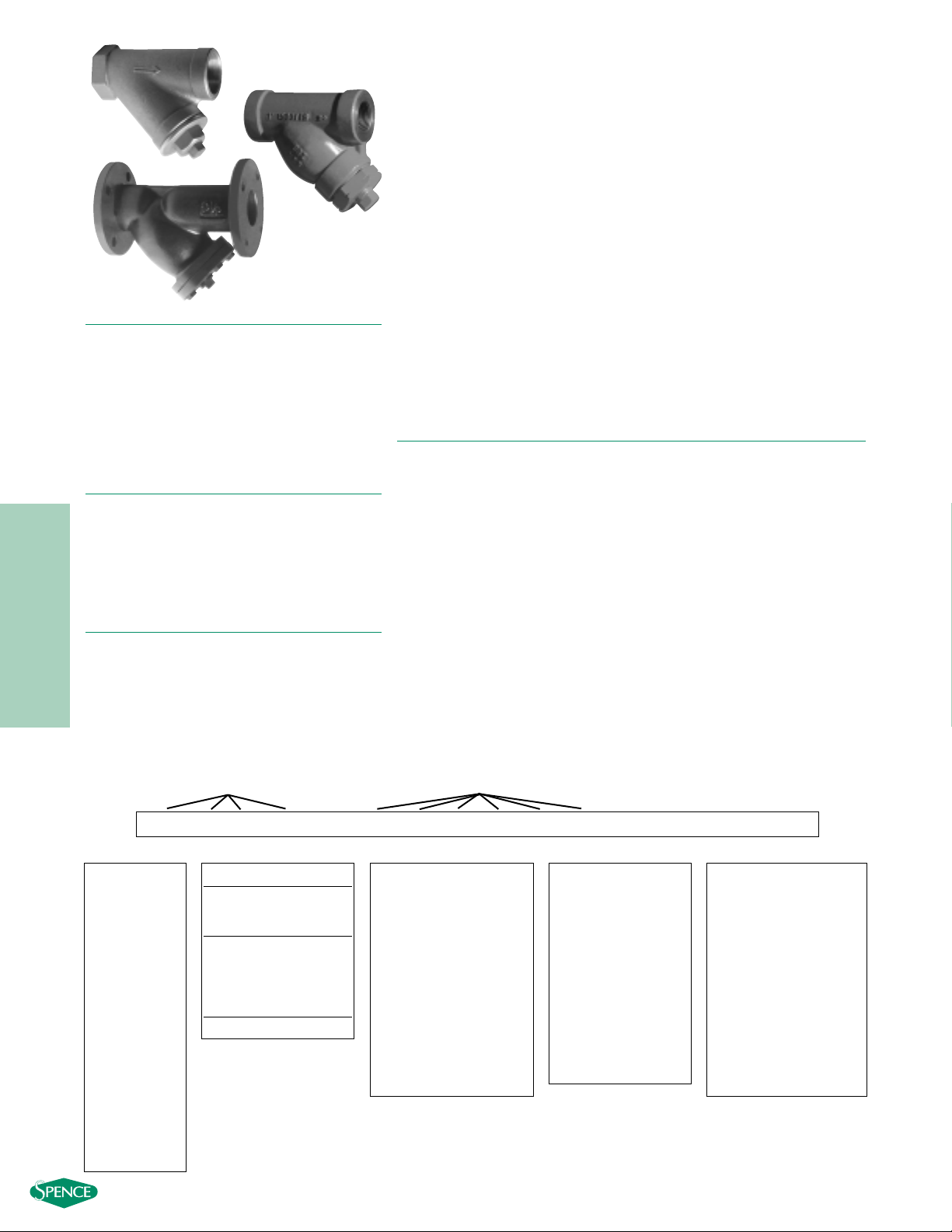
250Y SERIES
CAST IRON, BRONZE, DUCTILE IRON
Y STRAINERS NPT, FLANGED
PRESSURES TO 500 PSIG (34.5
BARG)
T
EMPERATURES TO
450°F (232°C)
● ANSI 250 PSIG rated strainers
● NPT and FF Flanges in accordance with ANSI 16.1,
16.15 and 16.4
● One piece cast body
● Upper and lower machined seats
● Generous screen area and properly proportioned
straining chamber to minimize initial pressure drop
while maximizing time between cleanings
● Drain/Blow-off connection furnished with plug
M
ODELS
● 250Y1T – Bronze or Cast Iron, NPT, Threaded Cover
● 250Y2F - Ductile Iron, Flanged, Bolted Cover
Add’l Requirements -
Position 16
Leave Blank
If not Required
D - Special Drain Size
F - Silicon Free
G - Special Gaskets
T - Special Testing
X - Oxygen Cleaning
Y - Other and / or
Multiple Specials
Indicate Specials
Clearly On the Order
Canadian Registration OEO591.9C BRZ & CI 250Y1 CI
Page 2
- 397 -
250Y SERIES
STRAINERS
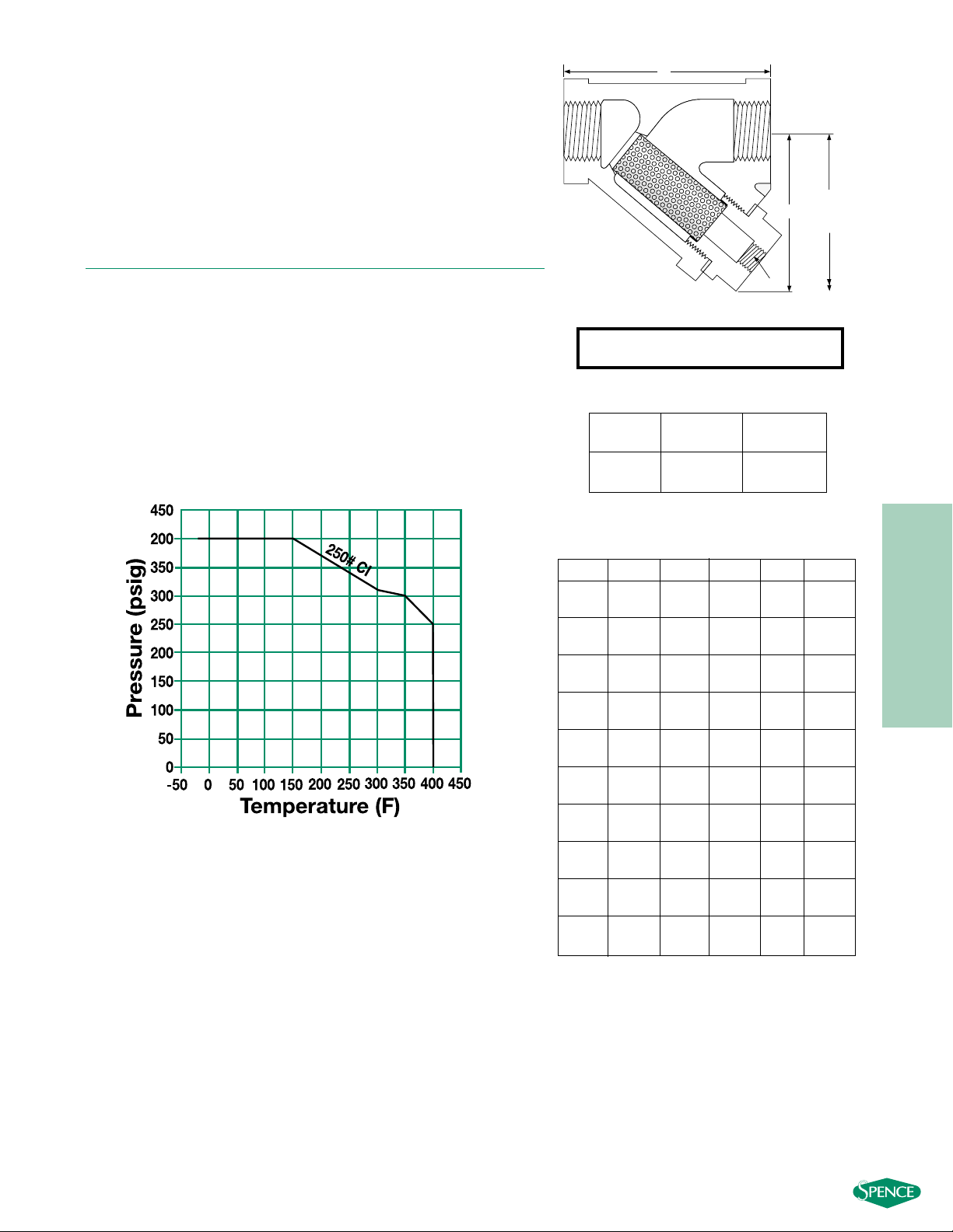
Connections: 1/4" – 3" NPT
SCREEN OPENINGS
STANDARD
SIZE SCREEN MATERIALS
1/4"- 2" 20 Mesh 304 SS
2
1
⁄2"- 3" 3/64" Perf 304 SS
250Y1 SERIES
CAST IRON Y STRAINERS NPT
SPECIFICATION
Y Strainer shall be straight flow design with NPT inlet/outlet connections. The
strainer shall be rated to ANSI 250 PSIG rating in accordance with ANSI
B16.4. The Strainer shall be cast iron body and the screen shall be size
______ perf / mesh 304 SS. The strainer shall be have an inlet size of ______
and Open Area Ratio of _______. The Y Strainer shall be SSI 250Y1 Series.
MATERIALS OF C
ONSTRUCTION
Body ……………………………………………………………A126-B
Cap/Cover ……………………………………………………A126-B
Screen1…………………………………………………………304 SS
Plug2……………………………………………………………A126-B
Gasket1…………………………………………………………Graphite
1. Recommended Spare Parts
2. Materials of equivalent strength may be substituted
PRESSURE/TEMPERATURE CHART
ASME B16.4
A
B
C
CLEARANCE
FOR SCREEN
REMOVAL
D N.P.T
SIZE A B C E WEIGHT
1
⁄4 3 3⁄16 23
1
⁄8
1
⁄4 1.50
(8) (81) (50) (80) (8) (.70)
3
⁄
8 3
3
⁄
16 23
1
⁄
8
1
⁄
4 1.50
(10) (81) (50) (80) (8) (.70)
1
⁄
2 3
3
⁄
16 23
1
⁄
8
1
⁄
4 1.50
(15) (81) (50) (80) (8) (.70)
3
⁄
4 3
3
⁄
4 2
11
⁄
16 3
11
⁄
16
3
⁄
8 2.50
(20) (95) (68) (94) (10) (.50)
1433
11
⁄
16
3
⁄
8 3.00
(25) (102) (62) (94) (10) (1.4)
11⁄4 53
7
⁄16 51⁄16
3
⁄4 6.00
(32) (127) (87) (129) (20) (1.4)
11⁄2 53⁄4 325⁄32 53⁄4
3
⁄4 8.00
(40) (146) (96) (146) (20) (3.6)
274
11
⁄32 71⁄4 1 14.00
(50) (178) (110) (184) (25) (3.6)
21⁄2 91⁄4 63⁄32 83⁄4 11⁄2 29.0
(65) (235) (155) (222) (40) (10)
3107
13
⁄32 91
1
⁄2 38.0
(80) (254) (188) (2.29) (40) (13.6)
DIMENSIONS inches (mm)
AND WEIGHTS pounds (kg)
Dimensions shown are subject to change.
Contact factory for certified prints when required.
E N.P.T.
Page 3

- 398 -
250Y SERIES
STRAINERS
Connections: 1/2" – 3" NPT
SCREEN OPENINGS
STANDARD
SIZE SCREEN MATERIALS
1
⁄2" - 1" 30 Mesh 304 SS
1
1
⁄4" – 3" 20 Mesh 304 SS
250Y1 SERIES
BRONZE Y STRAINERS NPT
SPECIFICATION
Y Strainer shall be straight flow design with NPT inlet/outlet connections. The
strainer shall be rated to ANSI 250 PSIG rating in accordance with ANSI
B16.15. The Strainer shall be bronze body and the screen shall be size
______ mesh 304 SS. The strainer shall be have an inlet size of ______ and
Open Area Ratio of _______. The Y Strainer shall be SSI 250Y1 Series.
M
ATERIALS OF CONSTRUCTION
Body ………………………………………………………………B584
Cap…………………………………………………………………B584
Screen1…………………………………………………………304 SS
Plug…………………………………………………………………B584
Gasket1…………………………………………………………Silicone
1. Recommended Spare Parts
SIZE A B C E WEIGHT
1
⁄2 215⁄16 21⁄8 31⁄2
3
⁄8 .9
(15) (75) (54) (89) (10) (0.4)
3
⁄4 33⁄8 23⁄8 41⁄2
3
⁄8 1.3
(20) (86) (60) (114) (10) (0.6)
14
1
⁄16 353⁄4 2.1
(25) (103) (76) (127) (20) (1.0)
11⁄4 415⁄16 37⁄16 53⁄4
3
⁄4 3.0
(32) (125) (87) (146) (20) (1.4)
11⁄2 53⁄4 313⁄16 63⁄8
3
⁄4 4.0
(40) (146) (97) (162) (20) (1.8)
2611⁄
16 4
9
⁄
16 9
1
⁄
16
3
⁄
4 7.1
(50) (170) (116) (230) (20) (3.2)
21⁄2 71⁄2 47⁄8 10 11⁄4 10.1
(64) (191) (124) (254) (32) (4.6)
38
1
⁄2 51⁄2 103⁄8 11⁄4 13.3
(76) (216) (140) (264) (32) (6.1)
DIMENSIONS inches (mm)
AND WEIGHTS pounds (kg)
* Consult factory for dimensions.
Dimensions shown are subject to change.
Contact factory for certified prints when required.
E N.P.T.
PRESSURE/TEMPERATURE CHART
ANSI B16.15
Page 4

- 399 -
250Y SERIES
STRAINERS
Connections: 2" – 12" RF Flanges
SCREEN OPENINGS
STANDARD
SIZE SCREEN MATERIALS
2" - 3" 3/64" Perf. 304 SS
4" – 12" 1/8" Perf. 304 SS
250Y2 SERIES
DUCTILE IRON Y STRAINERS FLANGED
SPECIFICATION
Y Strainer shall be straight flow design with RF Flanged inlet/outlet
connections. The strainer shall be rated to ANSI 250 PSIG rating in
accordance with ANSI B16.1. The Strainer shall be Ductile Iron and the
screen shall be size ______ perf 304 SS. The strainer shall be have an inlet
size of ______ and Open Area Ratio of _______. The Y Strainer shall be SSI
250Y2 Series.
MATERIALS OF
CONSTRUCTION
Body …………………………………………………Ductile Iron A536
Cap ……………………………………………………Ductile Iron A536
Screen1…………………………………………………………304 SS
Plug………………………………………………………………A126-B
Gasket1…………………………………………………………Graphite
Bolt/Stud2………………………………………………………A307-B
Nut2…………………………………………………………………A563
1. Recommended Spare Parts
2. Materials of equivalent strength may be substituted
SIZE A B C D E WEIGHT
28
7
⁄8 61⁄8 91⁄8 2
1
⁄2 28
(50) (226) (156) (232) (51) (15) (13)
21⁄2 103⁄4 81⁄16 97⁄8 21⁄2 138
(65) (273) (205) (251) (64) (25) (17)
311
5
⁄8 87⁄16 111⁄4 3154
(80) (295) (214) (286) (76) (25) (24)
413
7
⁄8 95⁄8 15 4 1 110
(100) (353) (245) (381) (102) (25) (50)
516
3
⁄8 115⁄8 19 5 11⁄4 160
(125) (416) (295) (483) (127) (32) (73)
618
1
⁄2 125⁄8 223⁄4 61
1
⁄2 224
(150) (470) (321) (578) (152) (40) (102)
821
3
⁄8 163⁄8 273⁄4 81
1
⁄2 468
(200) (543) (416) (692) (203) (40) (212)
10 26 191⁄8 293⁄4 10 2 590
(250) (660) (486) (756) (254) (50) (268)
12 30 221⁄16 35 12 2 890
(300) (762) (560) (889) (305) (50) (404)
DIMENSIONS inches (mm)
AND WEIGHTS pounds (kg)
Dimensions shown are subject to change.
Contact factory for certified prints when required.
C
A
D
B
PRESSURE/TEMPERATURE CHART
ANSI B16.1
Page 5

- 400 -
250Y SERIES
STRAINERS
250Y SERIES
CAST IRON, BRONZE, DUCTILE IRON
PRESSURE DROP VS FLOW RATE
Water Service, Clean Basket, 1/32" - 1/4" Perforated Screen*
(Sizes 1⁄4" - 11⁄2")
(Sizes 2" - 12")
* For Gas, Steam or Air service, consult factory.
Steam Service Pressure Drop
Page 433
Correction Factors for Other Viscous
Liquids and/or Mesh Liners Page 432
Correction Factors for
Clogged Screens Page 432
10
1
PRESSURE DROP (PSIG)
0.1
0.1 1 10 100
10
1
1/4”
”
1-1/4
1-1/2”
3/8”
1/2”
FLOW RATE (GPM)
3/4”
1”
2-1/2”
3”
4”
5”
6”
8”
2”
10
”
12”
PRESSURE DROP (PSIG)
0.1
10 100 1000 10000
FLOW RATE (GPM)
Page 6
- 401 -
250Y SERIES
STRAINERS
250Y SERIES
CAST IRON, BRONZE, DUCTILE IRON
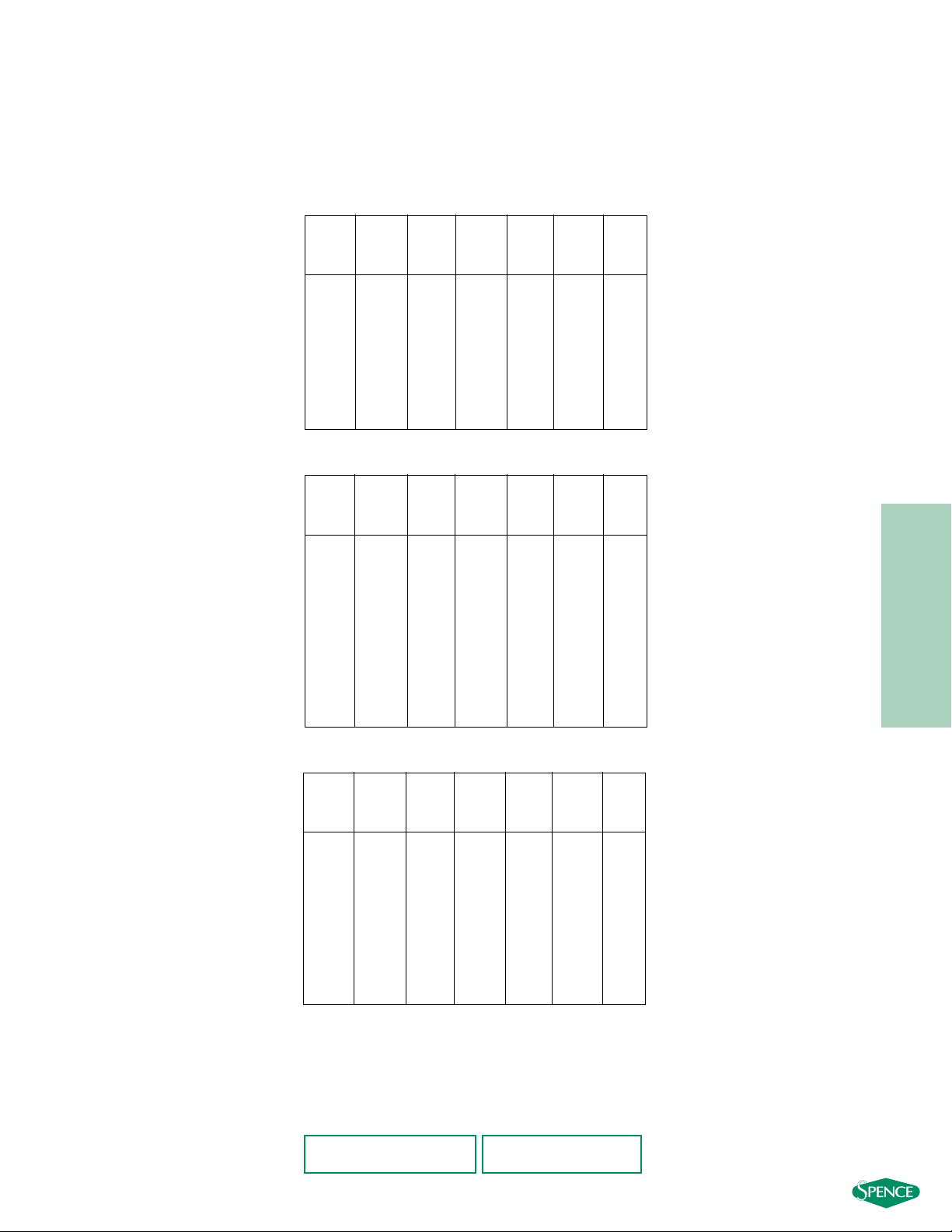
OPEN AREA RATIOS
with Standard Perforated Screen
Std Pipe Gross Free Open
Inlet Screen Screen Area
Size Mesh Opening Area Area Area Ratio
% (in2) (in2) (in2) (OAR)
1
⁄2
30 45 0.30 2.9 1.28 4.2
3
⁄4
30 45 0.53 5.6 2.52 4.7
1 30 45 0.86 9.0 4.03 4.7
1
1
⁄4
20 49 1.50 15.1 7.38 4.9
1
1
⁄2
20 49 2.04 21.7 10.64 5.2
2 20 49 3.36 29.2 14.31 4.3
2
1
⁄
2 20 49 4.79 35.9 17.61 3.7
3 20 49 7.39 49.9 24.45 3.3
BRONZE
Flange Gross Free Open
Perf. Inlet Screen Screen Area
Size Diameter Opening Area Area Area Ratio
(inches) % (in2) (in2) (in2) (OAR)
2 3/64 36 3.14 29.4 10.58 3.4
21⁄
2 3/64 36 4.91 46.0 16.56 3.4
3 3/64 36 7.07 57.0 20.51 2.9
4 1/8 40 12.57 99.0 39.59 3.2
5 1/8 40 19.63 146.5 58.58 3.0
6 1/8 40 28.27 174.0 69.60 2.5
8 1/8 40 50.27 327.3 130.91 2.6
10 1/8 40 78.54 495.2 198.08 2.5
12 1/8 40 113.10 645.0 257.99 2.3
DUCTILE IRON
Std Pipe Gross Free Open
Perf/Mesh Inlet Screen Screen Area
Size Diameter Opening Area Area Area Ratio
% (in2) (in2) (in2) (OAR)
1
⁄
4 20 49 0.30 3.7 1.80 5.9
3
⁄
8 20 49 0.30 3.7 1.80 5.9
1
⁄
2 20 49 0.30 3.6 1.74 5.7
3
⁄
4 20 49 0.53 6.3 3.11 5.8
1 20 49 0.86 7.9 3.85 4.5
1
1
⁄
4 20 49 1.50 13.0 6.35 4.2
1
1
⁄2 20 49 2.04 16.6 8.13 4.0
2 20 49 3.36 28.3 13.85 4.1
21⁄2 3/64 36 4.79 44.7 16.08 3.4
3 3/64 36 7.39 43.2 15.55 2.1
CAST IRON
Basket Burst Pressure
Page 435
OAR = Free Screen Area / Nominal Inlet Area
Free Screen Area = Opening % x Gross Screen Area
Values shown are approximate. Consult factory for exact ratios.
Other Screen Openings
Page 430
 Loading...