

Page 1
Series 23B, 123LP, N250, N250B
Water Pressure Reducing Valves
IS-2323A
Installation Instructions
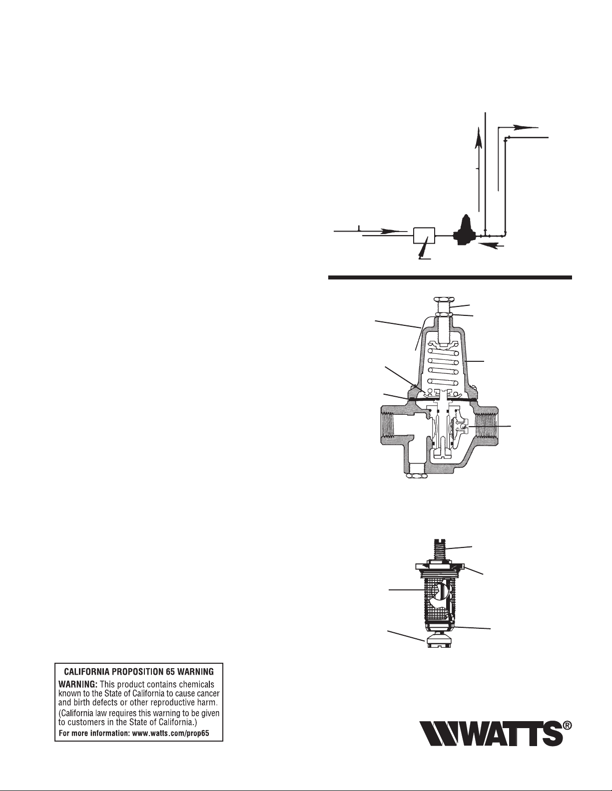
Install Valve in the line with arrow on valve body pointing
in the direction of flow.
This valve should be installed where it is accessible with sufficient clearance for cleaning, service or adjustment. Install
the reducing valve, when possible, before the sill cock line as
shown in diagram. Before installing the reducing valve, flush
out the line to remove loose dirt and scale which might damage valve disc and seat.
Horizontal installation is recommended. However, valve can be
installed in a vertical position. Regulator must be installed in an
accessible location to facilitate servicing the regulator.
To readjust reduced pressures, loosen adjusting screw nut
and turn adjusting screw clockwise to raise reduced pressure
and counterclockwise to lower reduced pressure.
When reducing valve is used, it makes a closed system; therefore, pressure relief protection must be provided on the downstream side of the reducing valve to protect equipment.
CAUTION: Anytime a reducing valve is adjusted, the use of a
pressure gauge is recommended to verify correct pressure setting. Do not bottom out adjusting screw or spring cage.
Servicing
This series is a new development for standard capacity domestic water regulation service. It has special unitized construction which consists of the seat, disc and stem assembly, and
strainer screen all together in one unit for complete replacement maintenance.
To clean or replace parts.
1. Remove spring cage and all parts above diaphragm.
2. Loosen and remove diaphragm lock nut, lock washer,
pressure plate, and diaphragm from valve stem.
3. Unscrew seat cylinder from body and remove entire assembly. For diaphragm replacement only, see part number.
4. While disassembled open gate valve to flush out collected
sediment.
NOTE: Cast iron body regulators (N250/N250B) are not
intended for buried or pit services.
From Street Main
Name Plate
Diaphragm
Lock Nut and
Pressure Plate
Diaphragm
(Size 1⁄2" - 560CA20)
(Size 3⁄4", 1" - 23B20)
Complete Replacement Assembly
Strainer
Screen
Main Line Service
Cold Water Supply
To Sill Cock
Reducing Valve
Meter
Adjusting Screw
Adjusting Screw Nut
Spring Cage
SA135B116
Bypass
Assembly for
models “B”
See reverse side for ordering information
Stem
Seat Cylinder
Disc
Integral
Stainless Steel
Valve Seat
Page 2
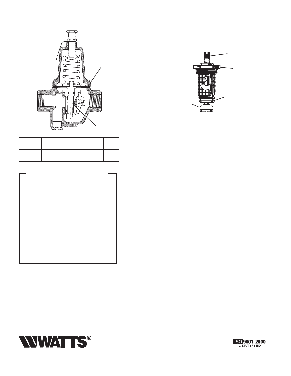
Series 23, 123, N250
Complete Replacement Assembly
(Includes Diaphragm)
Stem
Diaphragm
Seat Cylinder
Strainer
Screen
Integral
Disc
Stainless Steel
Valve Seat
Seat and Disc
Assembly
Ordering Kit Valve Size
Code No. No. Series Inches
878377
878339
1
⁄2" N250RK 23, 123, N250
3
⁄4" N250RK 23, 123, N250, N256 3⁄4
What is - thermal expansion?
The use of a water pressure reducing valve normally creates a closed system. When water is
heated in a closed system, it expands causing an
increase in pressure. This pressure may increase
to the set pressure of the relief valve (on the water
heater) causing it to drip, thus releasing the expanding water and protecting the system against
excessive pressure. This increase in the system
pressure over that regulated by the reducing valve
is call “thermal expansion pressure”.
Watts thermal expansion bypass model water
pressure reducing valve is an economical solution of this annoyance, since under certain conditions it allows the expanding water to escape
back into the supply main before it can affect the
relief valve.
NOTE: For additional detailed information on thermal expansion send for folder F-RV.
LIMITED WARR ANTY: Watts Regulator Co. (the “Company”) warrants each product to be free from defects in material and workmanship under normal usage for a period of one year from the date of
original shipment. In the event of such defects within the warranty period, the Company will, at its option, replace or recondition the product without charge.
THE WARRANTY SET FORTH HEREIN IS GIVEN EXPRESSLY AND IS THE ONLY WARRANTY GIVEN BY THE COMPANY WITH RESPECT TO THE PRODUCT. THE COMPANY MAKES NO OTHER WARRANTIES,
EXPRESS OR IMPLIED. THE COMPANY HEREBY SPECIFICALLY DISCLAIMS ALL OTHER WARRANTIES, EXPRESS OR IMPLIED, INCLUDING BUT NOT LIMITED TO THE IMPLIED WARRANTIES OF MERCHANTABILITY AND FITNESS FOR A PARTICULAR PURPOSE.
The remedy described in the first paragraph of this warranty shall constitute the sole and exclusive remedy for breach of warranty, and the Company shall not be responsible for any incidental, special or
consequential damages, including without limitation, lost profits or the cost of repairing or replacing other property which is damaged if this product does not work properly, other costs resulting from labor
charges, delays, vandalism, negligence, fouling caused by foreign material, damage from adverse water conditions, chemical, or any other circumstances over which the Company has no control. This warranty
shall be invalidated by any abuse, misuse, misapplication, improper installation or improper maintenance or alteration of the product.
Some States do not allow limitations on how long an implied warranty lasts, and some States do not allow the exclusion or limitation of incidental or consequential damages. Therefore the above limitations
may not apply to you. This Limited Warranty gives you specific legal rights, and you may have other rights that vary from State to State. You should consult applicable state laws to determine your rights. SO
FAR AS IS CONSISTENT WITH APPLICABLE STATE LAW, ANY IMPLIED WARRANTIES THAT MAY NOT BE DISCLAIMED, INCLUDING THE IMPLIED WARRANTIES OF MERCHANTABILITY AND FITNESS FOR A
PARTICULAR PURPOSE, ARE LIMITED IN DURATION TO ONE YEAR FROM THE DATE OF ORIGINAL SHIPMENT.
1
⁄2
Watts Thermal Expansion “Bypass” model water pressure reducing valves
not only control high water service pressure but also contain an “integral
thermal expansion bypass check valve” which reduces the frequency of
relief valve dripping caused by thermal expansion.
The built-in thermal expansion bypass, another Watts first, operates on the
principle of a check valve in reverse. Normally, the check is held closed by
the street main pressure, preventing any flow of water through it into the
system. However, when thermal expansion pressure increases to just 1 lb.
to 2 lbs. higher than the main pressure, the check valve opens passing the
expanding water back into the supply main at the rate it is expanded. Thus,
the expanding water is dissipated (as in an open system) and the relief valve
is not affected.
*Note: Effectiveness of the thermal expansion bypass feature is limited to
systems where the street main pressure is less that the allowable setting
of the pressure relief valve. Therefore, its use can be broadened by using a
relief valve with higher pressure setting (providing the working pressure of
the tank permits). While this feature limits the conditions causing relief valve
dripping, it in no way replaces a pressure relief valve which is necessary to
protect against other causes of excessive pressure.
When Ordering, Specify:
1. Ordering Code Number
2. Size of Valve
3. Type Number
4. Model Shown on Nameplate
Kit for No. 23, 123, N250, N250B
includes all items shown.
Water Safety & Flow Control Products
Canada: 5435 North Service Rd., Burlington, ONT. L7L 5H7; www.wattscanada.ca
USA: 815 Chestnut St., No. Andover, MA 01845-6098; www.watts.com
IS-2323A 0809 EDP# 1910259 ©Watts Regulator Company, 2008
 Loading...