

Page 1
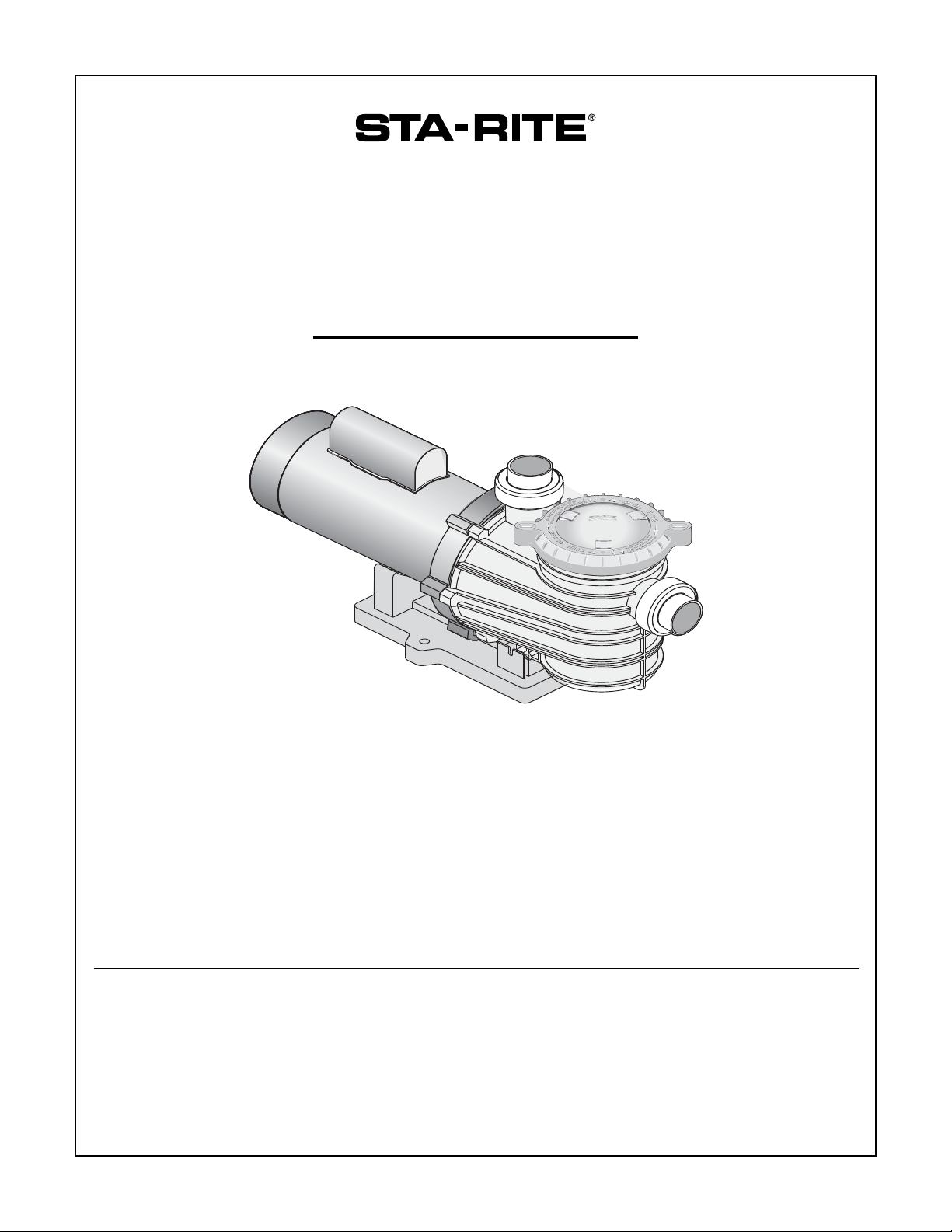
DYNA-WAVE
®
CENTRIFUGAL PUMP
WITH INTEGRAL TRAP
O W N E R’ S M A N U A L
INSTALLATION, OPERATION & PARTS
Pentair Water Pool and Spa, Inc.
© 2009 Pentair Water Pool and Spa, Inc. All rights reserved.
1620 Hawkins Ave., Sanford, NC 27330 • (919) 566-8000
10951 West Los Angeles Ave., Moorpark, CA 93021 • (805) 553-5000
Dyna-Wave®, Sta-Rite® and Pentair Water Pool and Spa® are registered trademarks of Pentair Water Pool and Spa, Inc. and/or its affiliated
companies in the United States and/or other countries. Plasto-Joint Stik® is a registered trademark of La-Co Industries, Inc. and Teflon® is a
registered trademark of E.I. Du Pont De Nemours and Company Corporation. Unless noted, names and brands of others that may be used in this
document are not used to indicate an affiliation or endorsement between the proprietors of these names and brands and Pentair Water Pool and Spa,
Inc. Those names and brands may be the trademarks or registered trademarks of those parties or others.
S752 Rev B (10/07/09)
This manual should be given to the end user of this pump;
its use will reduce service calls and chance of injury and will
lengthen pump life.
Page 2

2
‘MPRA’, SERIES PUMP
WITH TRAP
To avoid unneeded service calls, prevent possible
injuries, and get the most out of your pump, READ THIS
MANUAL CAREFULLY!
The Sta-Rite ‘MPRA’ Series Self-priming Centrifugal
pump:
• Is designed for use with water features or as a
centrifugal pump.
• Is an excellent performer; durable, reliable.
Table of Contents
Safety Instructions ......................................................2
Installation ...................................................................3
Pool Pump Suction Requirements ............................4-5
Electrical...................................................................5-6
Operation.....................................................................7
Storage/Winterizing ..................................................7-8
Pump Service .........................................................8-10
Repair Parts List ........................................................10
Troubleshooting Guide...............................................11
Warranty ....................................................................12
READ AND FOLLOW
SAFETY INSTRUCTIONS!
This is the safety alert symbol. When you see this
symbol on your system or in this manual, look for
one of the following signal words and be alert to the
potential for personal injury.
warns about hazards that will cause death,
serious personal
injury, or major property damage if ignored.
warns about hazards that can cause death,
serious personal
injury, or major property damage if ignored.
warns about hazards that will or can cause
minor personal injury or property damage if ignored.
NOTICE indicates special instructions not related to
hazards.
Carefully read and follow all safety instructions in this
manual and on equipment. Keep safety labels in good
condition; replace if missing or damaged.
Incorrectly installed or tested equipment
may fail, causing severe injury or property
damage.
Read and follow instructions in owner's
manual when installing and operating equipment. Have
a trained pool professional perform all pressure tests.
1. Do not connect system to a high pressure or city
water system.
2. Use equipment only in a pool or water feature
installation.
3. Trapped air in system can cause explosion. BE SURE
all air is out of system before operating or testing
equipment.
Before pressure testing, make the following safety
checks:
• Check all clamps, bolts, lids, and system accessories
before testing.
• Release all air in system before testing.
• Water pressure for test must be less than 25 PSI
(7.5 kg/cm
2
).
• Water Temperature for test must be less than 100° F.
(38° C).
• Limit test to 24 hours. After test, visually check
system to be sure it is ready for operation. Remove
trap lid and retighten hand tight only, see Figure 1.
NOTICE: These parameters apply to Sta-Rite®
equipment only. For non-Sta-Rite equipment, consult
manufacturer.
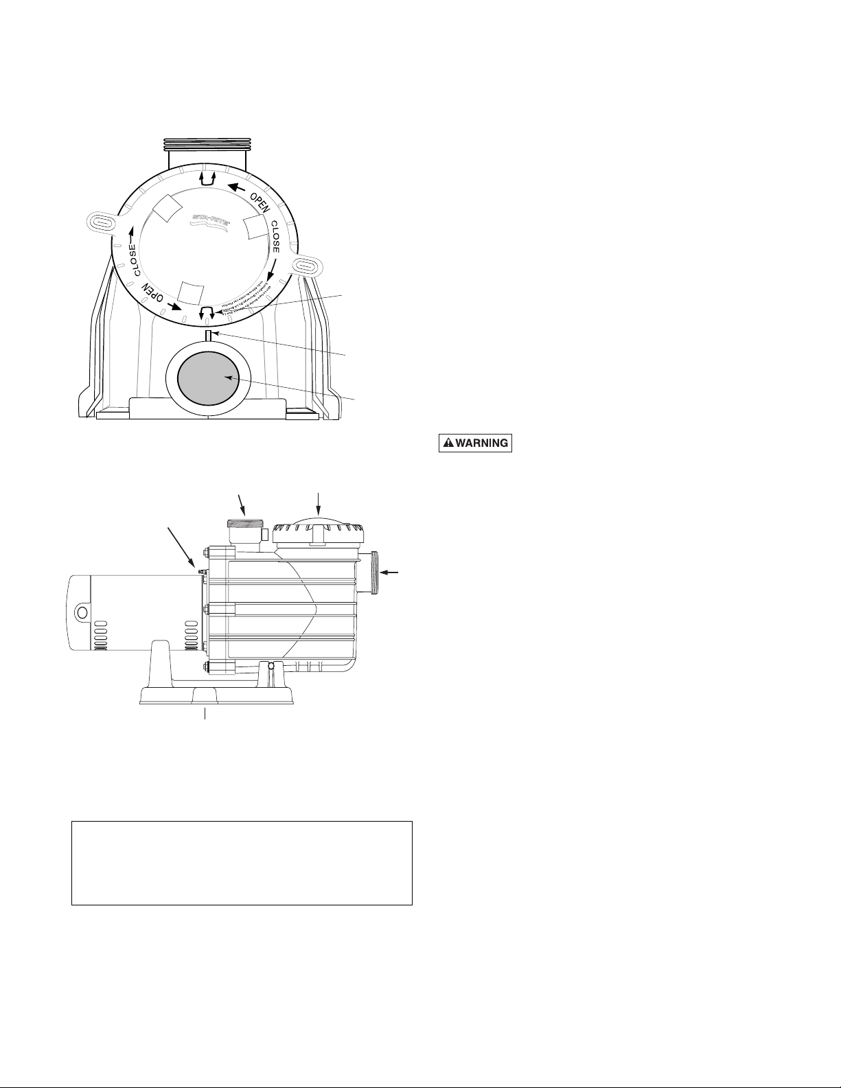
NOTICE: Do not start the pump until the strainer basket
cover is on and the tab, or rib, on the discharge port
aligns between the arrows.
IMPORTANT SAFETY
INSTRUCTIONS
Always follow basic safety precautions with this
equipment, including the following.
To reduce the risk of injury, do not
permit children to use this product unless they are
closely supervised at all times.
This pump is for use with permanently
installed pools and may also be used with hot tubs
and spas if so marked. Do not use with storable
pools. A permanently installed pool is constructed in
or on the ground or in a building such that it cannot
be readily disassembled for storage. A storable pool
is constructed so that it may be readily disassembled
for storage and reassembled to its original integrity.
SAVE THESE INSTRUCTIONS
Page 3
3
NOTICE: These parameters apply to Sta-Rite equipment
only. For non-Sta-Rite equipment, consult manufacturer.
INSTALLATION
(See Figure 2)
Only qualified, licensed personnel should install pump
and wiring.
Pump mount must:
Be located away from corrosive or flammable liquids.
Have enough ventilation to maintain air temperature at less
than the maximum ambient temperature rating (Max.
Amb.) listed on the motor model plate. If this pump is
installed in an enclosure/pump house, the enclosure must
have adequate ventilation and air circulation to keep the
temperature in the enclosure at or below the motor’s rated
ambient temperature whenever the pump is running.
Be solid - Level - Rigid - Vibration free. (To reduce
vibration and pipe stress, bolt pump to mount.)
Allow pump suction inlet height to be as close to water
level as possible. Pump will not lift water more than
10'(3m).
Allow use of short, direct suction pipe (To reduce friction
losses).
Allow for gate valves in suction and discharge piping.
Have adequate floor drainage to prevent flooding.
Be protected from excess moisture.
Allow adequate access for servicing pump and piping.
Fire and burn hazard. Modern motors run at
high temperatures. To reduce the risk of fire, do not allow
leaves, debris, or foreign matter to collect around the
pump motor. To avoid burns when handling the motor, let
it cool for 20 minutes before trying to work on it.
NOTICE: When connecting threaded pipe directly to pump,
use Teflon® tape or Plasto-Joint Stik® to seal connections.
Do not use pipe dope; pipe dope causes cracking in some
plastics and may damage components in piping system.
When connecting pipe to pump with union half, use
Teflon tape or Plasto-Joint Stik between pipe and union
adapter. Union collar to pump should be assembled dry
and hand-tight.
NOTICE: Pump suction and discharge connections have
molded in thread stops. DO NOT try to screw pipe in
beyond these stops.
Teflon Taping Instructions:
Use only new or clean PVC pipe fittings.
Wrap male pipe threads with one to two layers of Teflon
tape. Cover entire threaded portion of pipe.
Do not overtighten or tighten past thread stop in pump
port!
If leaks occur, remove pipe, clean off old tape, rewrap
with one to two additional layers of tape and remake the
connection.
NOTICE: Support all piping connected with pump!
Piping:
Use at least 2" (51mm) pipe. Increase size if a long run
is needed.
To avoid strains on the pump, support both suction and
discharge pipes independently. Place these supports
near the pump.
NOTICE: Port threads are: Internal - 2" NPT for direct
connection to pipe. External - 3-1/4" Buttress. Fits Sta-Rite
U11-200P Union Collar for quick disconnect pipe
connection. See Page 10 for Union Kits.
Figure 1 – Strainer basket cover alignment.
Figure 2.
P
P
M
M
U
U
P
P
N
N
S
O
W
O
O
S
R
B
B
R
I
W
I
A
O
R
R
R
N
R
E
O
O
E
A
S
S
W
N
T
E
G
E
G
E
B
N
N
W
I
I
S
T
R
R
E
N
-
-
B
G
I
D
D
S
I
L
I
A
L
N
L
G
E
I
E
E
G
L
T
T
R
A
A
A
A
T
E
T
H
G
O
O
C
R
R
R
S
A
I
H
D
C
S
I
D
Arrows
Ta b
Discharge
Por t
Discharge Port
to Filter or Pool
Strainer Basket
Cover
Bonding Lug
Pump may be bolted to level
foundation or mounting bracket.
Suction
Port
from
Pool or
Vacuum
Filters
5138 0905
Page 4
4
To avoid a strain left by a gap at the last connection,
start all piping at the pump and run pipe away from the
pump. To avoid airlocking, slope suction pipe slightly
upward toward the pump.
NOTICE: To prevent flooding when removing pump for
service, all flooded suction systems must have gate
valves in suction and discharge pipes.
PUMP SUCTION
REQUIREMENTS
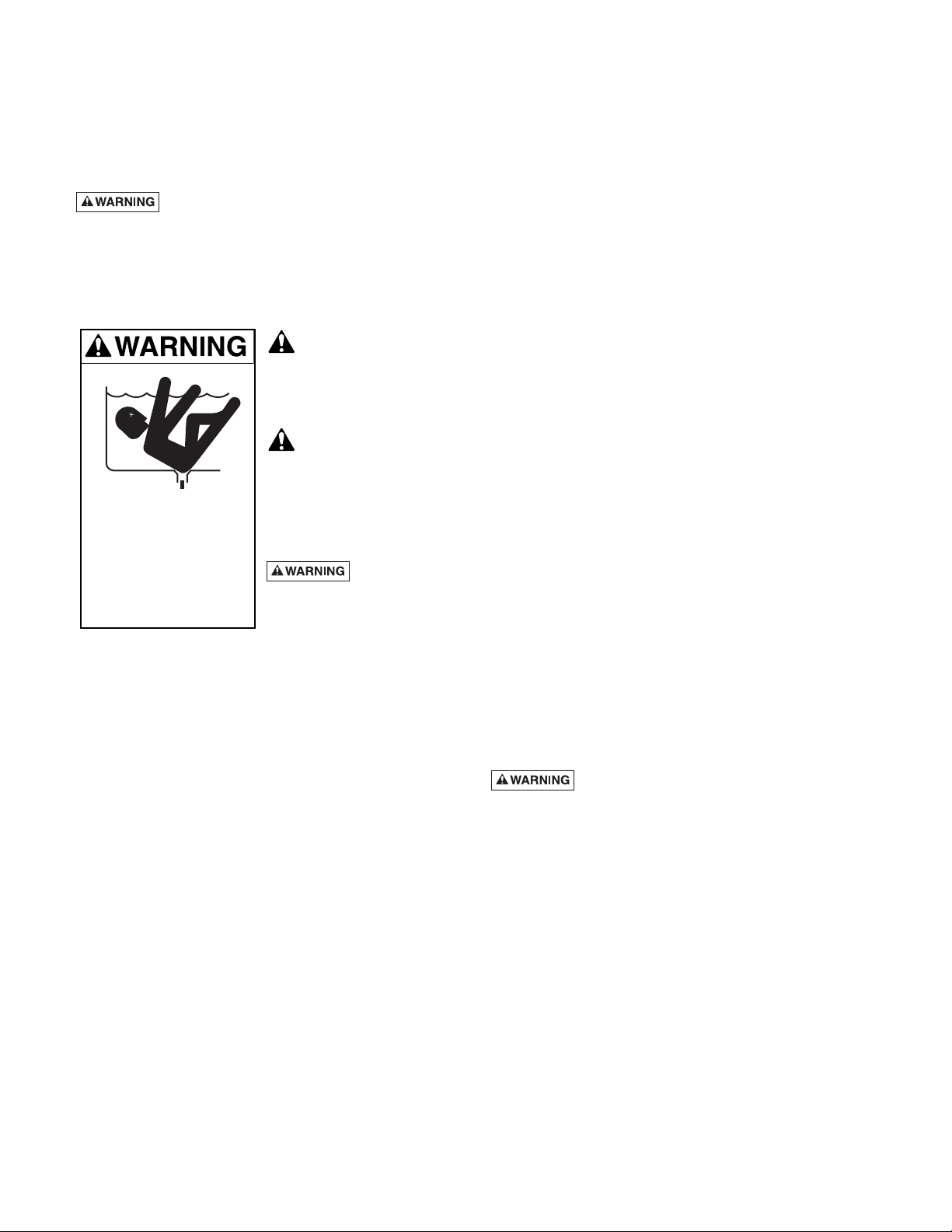
Pump suction is hazardous and can trap and drown
or disembowel bathers. Do not use or operate
swimming pools, spas, hot tubs or water features if a
suction outlet cover is missing, broken, or loose. Follow
the guidelines below for a pump installation which
minimizes risk to users of pools, spas, hot tubs and water
features.
Entrapment Protection
The pump suction system
must provide protection
against the hazard of
suction entrapment or hair
entrapment/entanglement.
Suction Outlet Covers
All suction outlet covers
must be maintained. They
must be replaced if
cracked, broken, or
missing.
See Page 5 for outlet cover
certification requirements.
All suction outlets must have
correctly installed, screwfastened covers in place.
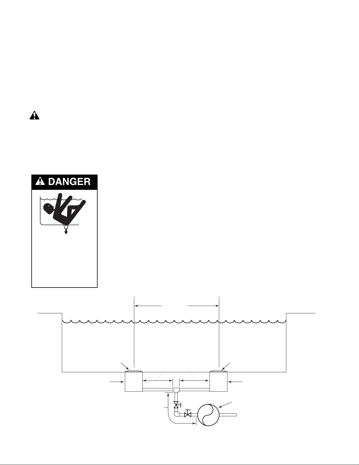
Suction Outlets Per Pump (Figure 2)
Provide at least two hydraulically balanced main drains,
with covers, as suction outlets for each circulating pump
suction line. The centers of the main drains (suction
outlets) on any one suction line must be at least three feet
apart.
The system must be built so that it cannot operate with
the pump drawing water from only one main drain (that is,
there must be at least two main drains connected to the
pump whenever it is running – see Figure 2). However, if
two main drains run into a single suction line, the single
suction line may be equipped with a valve which will shut
off both main drains from the pump (see Figure 2).
More than one pump can be connected to a single
suction line as long as the requirements above are met.
Water Velocity
The maximum water velocity through the suction fitting
or cover for any suction outlet must be 1.5 feet per
second unless the outlet complies with the latest
ASME/ANSI Specification for Suction Fittings For Use in
Swimming Pools, Spas, Hot Tubs, and Whirlpool
Bathtub Applications. In any case, do not exceed the
suction fitting’s maximum designed flow rate.
If 100% of the pump’s flow comes from the main drain
system, the maximum water velocity in the pump
suction hydraulic system must be six feet per second or
less even if one main drain (suction outlet) is completely
blocked. The flow through the remaining main drain(s)
must comply with the latest ASME/ANSI Specification
for Suction Fittings For Use in Swimming Pools, Spas,
Hot Tubs, and Whirlpool Bathtub Applications.
Hazardous suction.
Can trap hair or
body parts, causing
severe injury
or death.
Do not block
suction.
Figure 2 – Recommended pump suction layout.
IAPMO Certified
Anti-entrapment
Cover or Suction Fitting,
screw-fastened to
Main Drain Sump
Suction Outlet
(Main Drain)
Valves OK between
pump and Tee
At Least
3 Feet
No valves between
Tee and Main Drains
IAPMO Certified
Anti-entrapment
Cover or Suction Fitting,
screw-fastened to
Main Drain Sump
Suction Outlet
(Main Drain)
Pump
2762 0197
Page 5
5
Testing and Certification
Suction outlet covers must have been tested by a
nationally recognized testing laboratory and found to
comply with the latest ASME/ANSI Specifications for
Suction Fittings For Use in Swimming Pools, Spas, Hot
Tubs, and Whirlpool Bathtub Applications.
Fittings:
Fittings restrict flow; for best efficiency use fewest
possible fittings (but at least two suction outlets).
Avoid fittings which could cause an air trap.
Pool fittings must conform to International Association
of Plumbing and Mechanical Officials (IAPMO)
standards.
Use only non-entrapping suction fitting or double suction.
ELECTRICAL
Ground motor before connecting to electrical
power supply. Failure to ground motor can cause
severe or fatal electrical shock hazard.
Do not ground to a gas supply line.
To avoid dangerous or fatal electrical shock, turn
OFF power to motor before working on electrical
connections.
Ground Fault Circuit Interrupter (GFCI) tripping
indicates an electrical problem. If GFCI trips and
will not reset, have a qualified electrician inspect and
repair electrical system.
Exactly match supply voltage to nameplate
voltage. Incorrect voltage can cause fire or
seriously damage motor and voids warranty. If in doubt
consult a licensed electrician.
Voltage
Voltage at motor must be not more than 10% above or
below motor nameplate rated voltage or motor may
overheat, causing overload tripping and reduced
component life. If voltage is less than 90% or more than
110% of rated voltage when motor is running at full
load, consult power company.
Grounding/Bonding
Install, ground, bond and wire motor according to local
or National Electrical Code requirements.
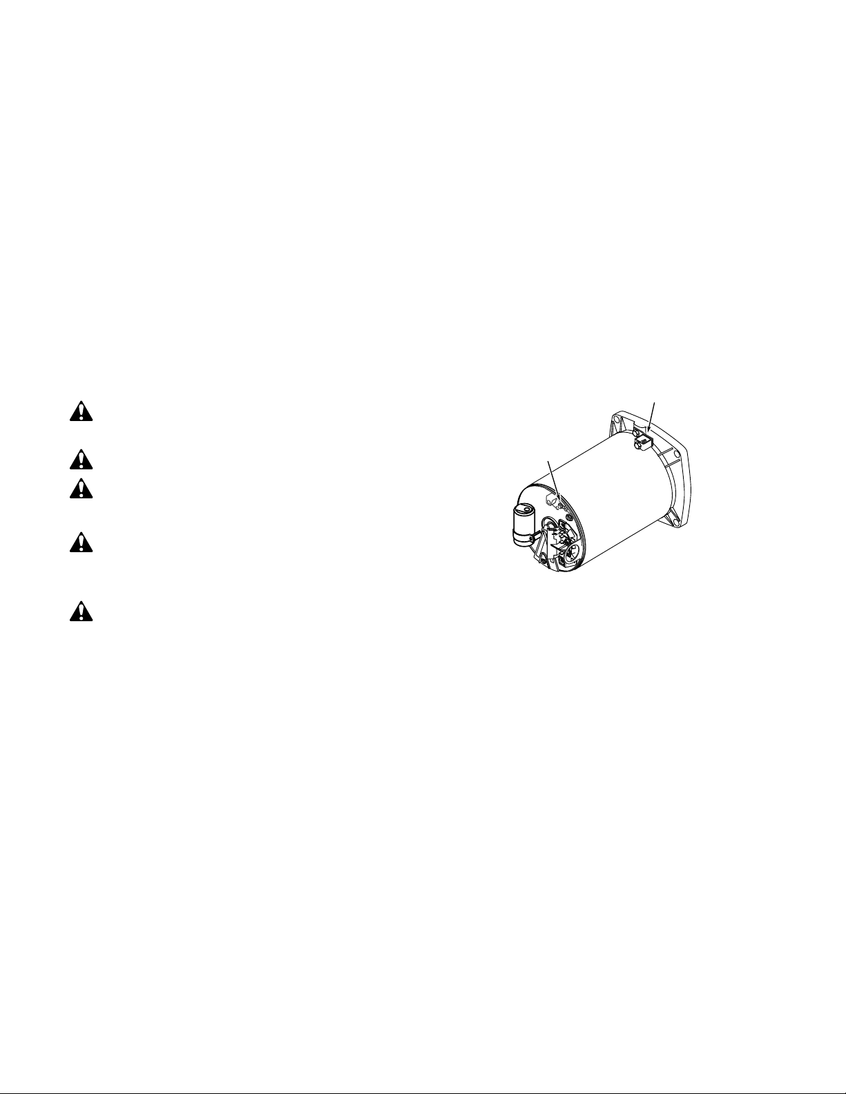
Permanently ground motor. Use green ground terminal
provided under motor canopy or access plate (See
Figure 3); use size and type wire required by code.
Connect motor ground terminal to electrical service
ground.
Bond motor to pool structure. Use a solid copper
conductor, size No. 8 AWG (8.4 sq.mm) or larger. Run
wire from external bonding lug (see Figure 3) to reinforcing
rod or mesh.
Connect a No. 8 AWG (8.4 sq.mm) solid copper
bonding wire to the pressure wire connector provided
on the motor housing and to all metal parts of the
swimming pool, spa, or hot tub and to all electrical
equipment, metal piping or conduit within 5 feet (1.5 m)
of the inside walls of swimming pool, spa, or hot tub.
Wiring
NOTICE: 3 phase models require magnetic motor
starters and external overload protection. If in doubt
about the procedure, consult a licensed electrician.
Pump must be permanently connected to circuit. Table
I, Page 6, give correct wire and circuit breaker sizes for
the pump alone. If other lights or appliances are also on
the same circuit, be sure to add their amp loads to
pump amp load before figuring wire and circuit breaker
sizes. (If unsure how to do this or if this is confusing,
consult a licensed electrician.) Use the load circuit
breaker as the master on-off switch.
Figure 3 – Typical ground screw and bonding lug
locations.
Bonding
Lug
Green
Ground
Screw
A
A
230V
115V
L2
L2
L1
L1
Page 6
6
Install a Ground Fault Circuit Interrupter (GFCI) in
circuit; it will sense a short-circuit to ground and
disconnect power before it becomes dangerous to pool
users. For size of GFCI required and test procedures for
GFCI, see manufacturer’s instruction.
In case of power outage, check GFCI for tripping (which
will prevent normal pump operation). Reset if
necessary.
NOTICE: If you do not use conduit when wiring motor,
be sure to seal wire opening on end of motor to prevent
dirt, bugs, etc., from entering.
Risk of dangerous or fatal electrical shock.
Be sure that power to the motor circuit is off before
working on wiring, wiring connections, or motor. Reinstall the motor end cover and all other wiring covers
before turning on the power.
1. Turn off power.
2. Remove the motor end cover.
To Wire a Single Speed, Single Voltage Motor
There are two terminals labeled L1 and L2. Attach the
power leads to these terminals. Either wire may attach to
either terminal.
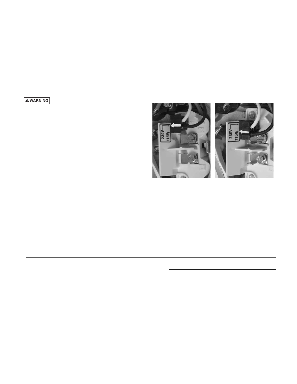
To Wire a Dual-Voltage Motor
Dual voltage motors have a plug to change from 230
volts (factory setting) to 115 volts.
1. If you have 230 volts motor supply voltage, confirm
that the plug is set for 230 volts. The arrow on the
plug will point to the 230 volt position. Note that plug
only connects with one prong in this position.
2. If you have 115 volt supply, pull the plug straight up
and place it on the two brass prongs as shown.
NOTE: Arrow is highlighted for clarity.
Figure 4B Voltage Change
Plug Set for 115 Volts.
Figure 4A -Voltage Change
Plug Set for 230 Volts.
TABLE I - RECOMMENDED FUSING AND WIRING DATA
Serv. to Motor - Dist. in Ft. (M)
AWG Wire Size (mm2)
Motor Branch Fuse Max Load Voltage/ 0-100' 101-200' 201-300'
Model HP Rating Amps* Amps Hz/Phase (0-30) (30-60) (60-90)
MPRA6B-202L
1/3 15/15 4.2/2.1 115/230/60/1 14/14(2/2) 14/14(2/2) 12/14(3/2)
1750 RPM
* Time delay fuses are recommended instead of standard fuses in any motor circuit.
Page 7
7
OPERATION
NOTICE: NEVER run pump dry. Running pump dry may
damage seals, causing leakage and flooding. Fill pump
with water before starting motor.
Before removing trap cover:
1. STOP PUMP before proceeding.
2. CLOSE GATE VALVES in suction and discharge
pipes.
3. RELEASE ALL PRESSURE from pump and piping
system.
If pump is being
pressure tested, be
sure pressure has been
released before removing
trap cover.
Do not block pump
suction. To do so with
body may cause severe or
fatal injury. Small children
using pool must ALWAYS
have close adult
supervision.
Fire and burn
hazard. Modern motors run
at high temperatures. To
reduce the risk of fire, do not
allow leaves, debris, or foreign matter to collect around
the pump motor. To avoid burns when handling the
motor, let it cool for 20 minutes before trying to work on
it. An automatic internal cutoff switch protects the motor
from heat damage during operation.
Priming Pump
Release all pressure from filter, pump, and piping
system; see the filter owner’s manual.
In a flooded suction system (water source higher than
pump), pump will prime itself when suction and
discharge valves are opened.
If pump is not in a flooded suction system, unscrew and
remove trap cover; fill trap and pump with water.
Clean and inspect O-Ring; reinstall on trap groove.
Do not lubricate the trap cover O-Ring. The original
equipment O-Ring contains a permanent internal
lubricant.
NOTICE: If you replace the O-Ring with a non-internally
lubricated O-Ring, you may need to apply a silicone
based lubricant. Replace trap cover on trap; turn
clockwise to tighten cover.
NOTICE: Tighten trap cover handle ring by hand only
(no wrenches)! See Figure 1, Page 3.
Pump should prime now. Priming time will depend on
vertical length of suction lift and horizontal length of
suction piping.
If pump does not prime, make sure that all valves are
open, suction pipe end is under water, pump is not trying
to lift water more than 10'(3m), and that there are no leaks
in suction pipe. See Troubleshooting Guide, Page 11.
Storage/Winterizing:
NOTICE: Allowing pump to freeze will damage pump
and void warranty!
NOTICE: Do not use anti-freeze solutions (except
propylene glycol) in your pool/spa system. Propylene
glycol, “RV antifreeze”, is non-toxic and will not damage
plastic system components; other anti-freezes are
highly toxic and may damage plastic components in the
system.
Drain all water from pump and piping when expecting
freezing temperatures or when storing pump for a long
time (see instructions below).
Keep motor dry and covered during storage.
To avoid condensation/corrosion problems, do not
cover pump with plastic.
For outdoor/unprotected installations:
1. Enclose entire system in a weatherproof enclosure.
2. To avoid condensation/corrosion damage, allow
ventilation; do not wrap system in plastic.
3. Use a 40% propylene glycol/60% water solution to
protect pump to -50° F (-46° C).
Draining Pump
Explosion hazard. Purging the system with
compressed air can cause components to explode, with
risk of severe injury or death to anyone nearby. Use only
a low pressure (below 5 PSI), high volume blower when
air purging the pump, filter, or piping.
Hazardous suction.
Can trap hair or
body parts, causing
severe injury
or death.
Do not block
suction.
Page 8
8
1. Pump down water level below all inlets to the pool.
To avoid dangerous or fatal electrical shock
hazard, turn OFF power to motor before draining
pump.
2. Remove trap cover and use low pressure air to blow
accumulated water from the piping system. Use a pry
bar or board to remove trap covers that have been
overtightened or have taken a set and cannot be
removed by hand. Lugs have been provided on the
trap lid to use a lever or pry bar for loosening (see
Figure 6).
3. Cap inlet piping after draining to keep water out of
the pipes.
4. To prevent pump from freezing, remove trap cover and
drain the tank body through the two drain plugs
provided.
A. Gravity drain system as far as possible.
B. Protect areas which retain water with non-toxic
propylene glycol antifreeze (“RV” antifreeze).
5. Clean pump thoroughly; replace trap cover.
NOTICE: Tighten trap cover by hand only (no
wrenches)! If pump is not anchored, use caution to
not break attached piping!
6. Be sure motor is kept dry and covered.
Startup For Winterized Equipment
1. Remove any temporary weather protection placed
around system for shutdown.
2. Follow filter manufacturer’s instructions for
reactivation of the filter.
3. Inspect all electrical wiring for damage or
deterioration over the shutdown period. Have a
qualified serviceman repair wiring as needed.
4. Inspect and tighten all watertight connections.
5. Open all valves in suction and return piping.
6. Remove any winterizing plugs in piping system.
7. Drain all antifreeze from system.
8. Close all drain valves and replace all drain plugs in
piping system.
9. Prime pump according to instructions on Page 7.
PUMP SERVICE
Pump should only be serviced by qualified personnel.
For best results, use only genuine Sta-Rite factory
parts.
Be sure to prime pump
(Page 7) before starting.
Before
removing trap cover:
1. STOP PUMP before
proceeding.
2. CLOSE GATE VALVES
insuction and discharge
pipes.
3.RELEASE ALL
PRESSURE from pump
and piping
system.
To avoid dangerous or
fatal electrical shock
hazard, turn OFF power to
motor before working on
pump or motor.
Aside from lubricating trap cover O-Ring, no lubrication
or regular maintenance is needed beyond reasonable
care and periodic cleaning of strainer basket.
If shaft seal is worn or damaged, repair as follows:
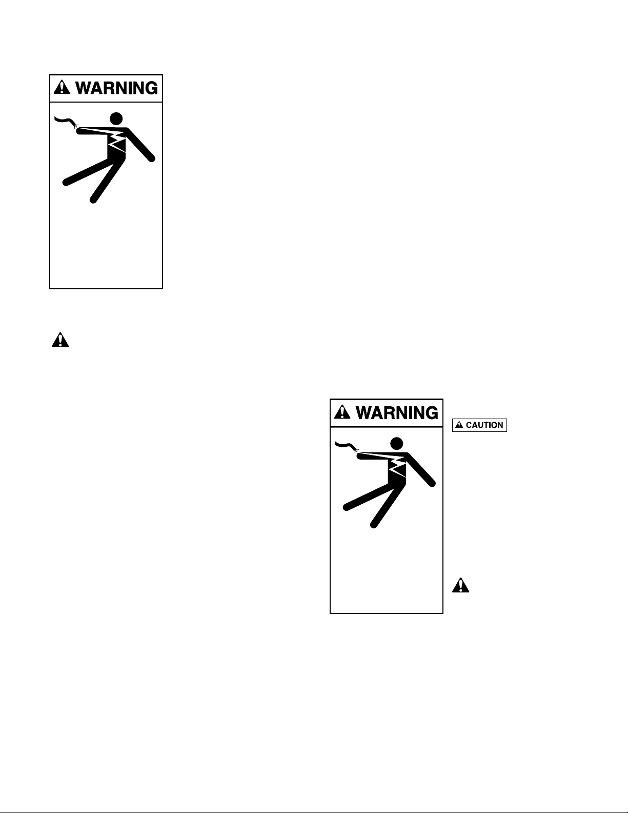
Hazardous voltage.
Can shock, burn,
or cause death.
Disconnect power
before working
on pump or motor.
Hazardous voltage.
Can shock, burn,
or cause death.
Disconnect power
before working
on pump or motor.
Page 9

9
Pump Dissasembly/Removing Old Seal
Disconnect power to pump motor.
Be sure valves on suction and return piping are
closed before starting work.
Release all pressure by opening all vents before
starting work.
1. Drain pump by removing drain plugs on bottom of
pump body and trap body.
2. Be sure there is no pressure in trap body; remove
cover (unscrew by turning counterclockwise).
3. Remove 6 nuts, lockwashers and flat washers holding
seal plate to pump body. Pull seal plate and motor
away from pump body. (You may have to
CAREFULLY use a screwdriver to separate body
from seal plate.)
4. Remove seven screws and washers holding diffuser
to seal plate. Remove diffuser.
5. Remove motor canopy. Being careful not to touch
capacitor terminals, loosen capacitor clamp and
move capacitor to one side.
6. Hold shaft with 7/16" open-end wrench on motor
shaft flats.
7. Unscrew impeller from shaft (turn counterclockwise
when facing it).
NOTICE: On 2 HP model, remove impeller
screw (left hand thread - turn clockwise) and
gasket before removing impeller. Inspect gasket
for damage, cracks, etc. Replace if damaged.
8. Remove four screws holding seal plate to motor.
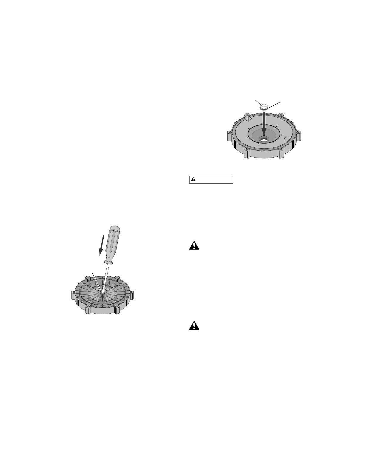
9. Place seal plate face down on flat surface and tap
out ceramic seat (Figure 5).
10. Remove slinger from motor shaft and inspect for
damage or abrasion.
11. Clean seal cavity in seal plate and clean motor
shaft.
Pump Reassembly/Installing New Seal
1. Ceramic seat must be clean and free of dirt, grease,
dust, etc. Wet outer edge with small amount of
liquid detergent; press ceramic seat into seal plate
cavity firmly and squarely with finger pressure (see
Figure 8).
2. If ceramic seat will not locate properly, remove it,
place face up on bench and reclean cavity.
Ceramic seat should now locate.
3. If seat still will not locate properly, place a
cardboard washer over the polished face and use a
piece of 3/4" (19mm) standard pipe for pressing
purposes.
NOTICE: Be sure not to scratch or mar polished
surface or seal will leak.
4. Replace slinger on end of motor shaft so that
impeller sleeve will push it into position. If slinger
shows signs of wear or damage, replace it.
5. Remount seal plate on motor. Tighten bolts to 6080 inch-lbs. (69-92 kg/cm) torque.
6. Apply a small amount of liquid detergent to inside
diameter of rotating half of seal.
7. Slide rotating seal member, polished carbon face
out, over impeller sleeve until rubber drive ring hits
back of impeller.
NOTICE: Be sure not to nick or scratch polished
seal face; seal will leak if face is damaged.
8. Screw impeller onto shaft (clockwise); this will
automatically locate seal in seal plate. NOTICE: On
2 and 2-1/2 HP models; install impeller gasket
and lock screw (left-hand thread - turn
counterclockwise). Torque lock screw to 50-55
inch-lbs. (57.6-63 kg/cm).
9. Mount diffuser on seal plate; tighten screws to 1014 inch-lbs. (11.2-16.1 kg/cm) torque.
10. Assemble motor and seal plate to pump body with
nuts, flat washers and lock washers. Torque nuts to
120-130 in-lbs. (138-150 kg/cm).
11. Prime pump according to instructions on Page 7.
Figure 5
Figure 8
Mechanical seal
ceramic seat
Polished
surface
Rubber
surface
Page 10

10
24
Key Part MPRA6B-143L
No. Description Qty. 1/3 HP
1 Motor, 115/230V 1750 RPM 1 62003-2088
2 Screw #10-32x1/2" 1 U30-692SS
3 Bonding Lug 1 U17-568
4 Slinger 1 17351-0009
5 Seal Plate 1 C3-184P
6 Seal Plate Cord Ring 1 U9-373
7 Shaft Seal 1 37400-0027S
8 Impeller 1 C105-236PDA
8A O-Ring Gasket 1 33455-1047
8B Impeller Screw 1 37337-6080
9 Diffuser 1 C1-270P
10 Diffuser “O” Ring 1 U9-374
11 Tank and Trap Body (Only) 1 C76-71P
12 Trap Cover 1 17307-01111
13 Trap Cover “O” Ring 1 35505-1440
14 Trap Basket 1 C8-58P
15A Drain Plug 2 U178-920P
15B Mounting Screw 5/16-14x5/8" 2 U30-919SS
16 Base 1 C4-77P
17 Motor Pad 1 C35-45
18 Screw #8-32x7/8" Rd. Hd. 7 U30-542SS
19 Lock Washer #8 Ext. Tooth 7 U43-21SS
20 Flat Washer 3/8" 6 U43-62SS
21 Lock Washer 3/8" 6 U43-12SS
22 Nut 3/8-16 Hex. nickel-plated brass 6 71403
23 Cap Screws 3/8-16x1" Hex. 4 U30-74SS
• Nameplate 1 32155-4071
• Tag, “CAUTION This pump equipped with 1 U63-13
mechanical shaft seal…”
• Voltage Sticker 1 U27-153
• Decal “Overtight trap lid…” 1 U27-644
• Tag, “WARNING/CAUTION/Instructions...” 1 C63-12
• Not illustrated.
REPAIR PARTS LIST
Pkg. 188 2" Slip 1/2 Union Kit.
Note that this kit includes both
inlet and outlet connections.
Includes:
U11-200PS Union Collar - Qty 2
U9-362 O-Ring - Qty 2
U11-196P 2" Slip Adapter - Qty 2
Box A
23
1
22
21
2
3
20
4
5
6
7
19
15B
8
16
18
8A
17
See
Box A
8B
9
10
11
12
13
14
15A
See
Box A
5136 0905
Page 11

11
TROUBLESHOOTING
Read and understand safety and
operating instruc-tions in this manual
before doing any work onpump!
Only qualified personnel should electrically test pump motor!
FAILURE TO PUMP; REDUCED CAPACITY OR
DISCHARGE PRESSURE
Suction leaks/lost prime:
1. Pump must be primed; make sure that pump
voluteand trap are full of water. See priming
instructions, Page 7.
2. Make sure there are no leaks in suction piping.
3. Make sure suction pipe inlet is well below the
waterlevel to prevent pump from sucking air.
4. If suction trap gasket is defective, replace it.
5. Make sure pump is not trying to lift water more
than10' (3m).
6. Make sure suction pipe is at least 2" (51mm) in
diameter.
CLOGGED PIPE/TRAPPED IMPELLAR/WORN
IMPLELLAR
7. Make sure suction trap is not clogged; if it is, cleantrap
and strainer.
8. Make sure impeller is not clogged (follow steps 1
through 7 under “Removing Old Seal”, Page 9; check
impeller for clogging; follow steps 7 through 11under
“Installing New Seal”, Page 9, for reassembly).
9. Impeller and diffuser may be worn. If so, order
replacement parts from Repair Parts List, Page 10.
ELECTRICAL
10. Pump may be running too
slowly; check voltage at motor
terminals and at meter while
pump is running. If low, see wiring
instructions or consult power
company. Check for loose
connections.
11. Pump may be too hot.
(A)Check line voltage; if less than
90% or morethan 110% of rated
voltage consult a licensed
electrician.
(B) Increase ventilation.
(C) Reduce ambient temperature.
(D)Tighten any loose
connections.
MECHANICAL
12. If suction and discharge piping
are not adequately supported,
pump assembly will be strained. See “Installation”, Page 3.
13. Do not mount pump on a wooden platform! Securely mount on
concrete platform for quietest performance.
Hazardous voltage.
Can shock, burn,
or cause death.
Disconnect power
before working
on pump or motor.
Page 12

For customer support or technical information about
this product, contact the installer or call:
Phone: (800) 831-7133 Fax: (800) 284-4151
Visit www.pentairwater.com and staritepool.com
S752 Rev B (10-09-09)
Page 13

DYNA-WAVE
BOMBA CENTRÍFUGA
CON COLECTOR INTEGRAL
MANUAL DEL PROPIETARIO
INSTALACIÓN, OPERACIÓN Y PIEZAS
© 2009 Pentair Water Pool and Spa, Inc. Todos los derechos reservados.
1620 Hawkins Ave., Sanford, NC 27330 (919) 566-8000
10951 West Los Angeles Ave., Moorpark, CA 93021 (805) 553-5000
Starite®, Dyna-Wave®, Pentair Water Pool and Spa® es marca comercial y/o marca registrada de Pentair Water Pool and
Spa, Inc. y/o de sus compañías afiliadas en Los Estados Unidos y/o en otros países. Plasto-Joint Stik® es marca comercial y/o
marca registrada de La-Co Industries, Inc. and Teflon® es marca comercial y/o marca registrada de E.I. Du Pont De Nemours and
Company Corporation. A menos que sea indicado, los nombres y marcas de otras compañias pueden ser utilizados en este
documento pero no son utilizados para indicar una afiliación o endorse entre los propietarios de estos nombres y marcas y
Pentair Water Pool and Spa, Inc. Esos nombres y marcas pueden ser las marcas comerciales o registradas de esas
entidades u otros.
S752 Rev B (10-07-09)
Este manual se debe entregar al usuario final de esta bomba; su uso
reducirá las llamadas de servicio y las posibilidades de lesiones, y
alargará la vida útil de la bomba.
®
5137 0905
Page 14

2
BOMBA DE LA SERIE
‘MPRA’, CON COLECTOR
Para evitar llamadas innecesarias de servicio, evitar
posibles lesiones y obtener el máximo de su bomba,
¡LEA ESTE MANUAL CON ATENCIÓN!
La bomba centrífuga autocebadora de la Serie
‘MPRA’ de Sta-Rite:
• Ha sido diseñada para usar con agua o como
bomba centrífuga.
• Tiene un desempeño excelente, es duradera y
fiable.
Îndice
Instrucciones de seguridad............................................2
Instalación .....................................................................3
Requerimientos de aspiración
para bombas de albercas...........................................4-5
Información eléctrica ..................................................5-6
Operación......................................................................7
Almacenamiento/Preparación para el invierno...........7-8
Servicio de la bomba................................................8-10
Lista de piezas para reparaciones...............................10
Guía para la localización de fallas...............................11
Garantía ......................................................................12
¡LEA Y SIGA LAS
INSTRUCCIONES
DE SEGURIDAD!
Este es el símbolo de alerta de seguridad. Cuando usted
vea este símbolo en su sistema o en este manual,
busque alguna de las siguientes palabras de advertencia y
esté alerta a la posibilidad de lesiones personales:
advierte acerca de los peligros que
provocarán muerte, lesiones personales graves, o daños
materiales considerables si se ignoran.
advierte acerca de los peligros que
pueden provocar muerte, lesiones personales graves, o daños
materiales considerables si se ignoran.
advierte acerca de los peligros que
provocará o pueden provocar lesiones personales o daños
materiales menores si se ignoran.
La etiqueta AVISO indica instrucciones especiales que no están
relacionadas con los peligros.
Lea y siga cuidadosamente todas las instrucciones de seguridad
en este manual y en la máquina. Mantenga las etiquetas de
seguridad en buen estado; reemplace las que falten o estén
dañadas.
Las máquinas que se instalan o se
prueban en forma incorrecta pueden fallar,
provocando lesiones graves o daños
materiales considerables.
Cuando instale y opere la máquina, es importante que lea y
siga las instrucciones del manual del propietario. Haga que un
profesional capacitado en instalaciones en albercas realice
todas las pruebas de presión.
1. No conecte el sistema a un sistema de alta presión o de
aguas públicas.
2. Use la máquina sólo en instalaciones de agua o en
albercas.
3. El aire atrapado en el sistema puede provocar explosiones.
VERIFIQUE que todo el aire haya salido del sistema antes
de operar la máquina o de hacer una prueba.
Antes de realizar la prueba de presión, verifique lo siguiente:
• Inspeccione todas las abrazaderas, los pernos, las tapas y
los accesorios del sistema antes de realizar una prueba.
• Libere todo el aire en el sistema antes de realizar una
prueba.
• Ajuste las tapas del colector Sta-Rite a una torsión de 30 ft.
lbs. (4.1 kg-m) para hacer la prueba.
• La presión del agua para la prueba debe ser inferior a 25
PSI (7.5 kg/cm
2
).
• La temperatura del agua para la prueba debe ser inferior a
100Þ F (38Þ C).
• Limite la prueba a 24 horas. Después de realizarla,
inspeccione el sistema visualmente, para verificar que esté
listo para funcionar. Saque la tapa del colector y vuelva a
ajustarlo a mano solamente.
INSTRUCCIONES
IMPORTANTES DE
SEGURIDAD
Siempre observe las precauciones básicas de seguridad
con esta máquina, que incluyen lo siguiente:
Para reducir el peligro de lesiones,
no permita que los niños usen este producto a menos que
estén bajo supervisión estricta en todo momento.
Esta bomba se debe usar en albercas
de instalación permanente y se puede usar con baños
termales y jacuzzis si así se indica. No la use con albercas
desmontables. Una alberca de instalación permanente
está construida dentro o sobre el suelo o en un edificio, y
no se puede desarmar fácilmente para guardarla. Una
alberca desmontable se ha construido de manera que se
pueda desarmar fácilmente para guardarle y se pueda
volver a armar para obtener su integridad inicial.
CONSERVE ESTAS
INSTRUCCIONES
PELIGRO
ADVERTENCIA
PRECAUCIÓN
ADVERTENCIA
PRECAUCIÓN
Page 15
3
AVISO: Estos parámetros corresponden sólo a máquinas
Sta-Rite. Para máquinas que no son de la marca Sta-Rite,
consulte con el fabricante.
INSTALACIÓN (Figura 2)
La bomba y los cables deben ser instalados sólo por personas
competentes y autorizadas.
La instalación de la bomba debe:
Estar ubicada lejos de líquidos corrosivos o inflamables.
Tener suficiente ventilación para mantener la temperatura del
aire por debajo de la clasificación máxima de temperatura
ambiente (Máx. Amb.) indicada en la placa del modelo del
motor. Si esta bomba está instalada en un recinto/estación de
la bomba, el recinto deberá tener una ventilación y una
circulación de aire adecuadas para mantener la temperatura
dentro del mismo a la temperatura ambiente nominal del motor
o por debajo de la misma, siempre que la bomba esté
funcionando.
Ser firme - nivelada - rígida - sin vibraciones. (Para reducir las
vibraciones y la tensión en las tuberías, emperne la bomba al
dispositivo de montaje)
Permitir que la altura de la admisión de aspiración de la bomba
esté lo más cerca posible del nivel del agua. La bomba no
levantará agua a más de 10 pies de altura (3 m).
Permitir el uso de tubos de aspiración cortos y directos (Para
reducir las pérdidas por fricción).
Permitir la instalación de válvulas de compuerta en los tubos
de aspiración y de descarga.
Tener un desagüe adecuado en el suelo para evitar
inundaciones.
Estar protegida contra una humedad excesiva.
Permitir el acceso adecuado para los trabajos de servicio de la
bomba y de las tuberías
.
Peligro de incendio y de quemaduras.
Los motores modernos funcionan a altas temperaturas. Para
reducir el peligro de incendio, no permita que hojas, escombros o
partículas extrañas se acumulen alrededor del motor de la
bomba. Para evitar quemaduras cuando se trabaje con el motor,
deje que éste se enfríe durante unos 20 minutos antes de
manipularlo.
AVISO: Cuando conecte un tubo fileteado directamente a la
bomba, use cinta de Teflón o Plasto-Joint Stik
1
para sellar las
conexiones. No use compuesto para tubos, ya que éste
provoca rajaduras en ciertos plásticos y puede dañar los
componentes del sistema de tubos.
Cuando conecte el tubo a la bomba con una mitad de unión,
use cinta de Teflón o Plasto-Joint Stik entre el tubo y el
adaptador de la unión. El collarín de unión a la bomba se debe
ensamblar en seco y apretar a mano.
AVISO: Las conexiones de aspiración y de descarga tienen
topes de rosca moldeados. NO trate de atornillar una tubería
más allá de estos topes.
AVISO: Las roscas de los orificios son: Internos - 2” NPT
para conexión directa a la tubería. Externas - 3-1/4”
Trapezoidal. Se adapta al collarín de unión Sta-Rite U11200P para una conexión a tubos de desconexión rápida.
Consulte la página 10 para los juegos de uniones.
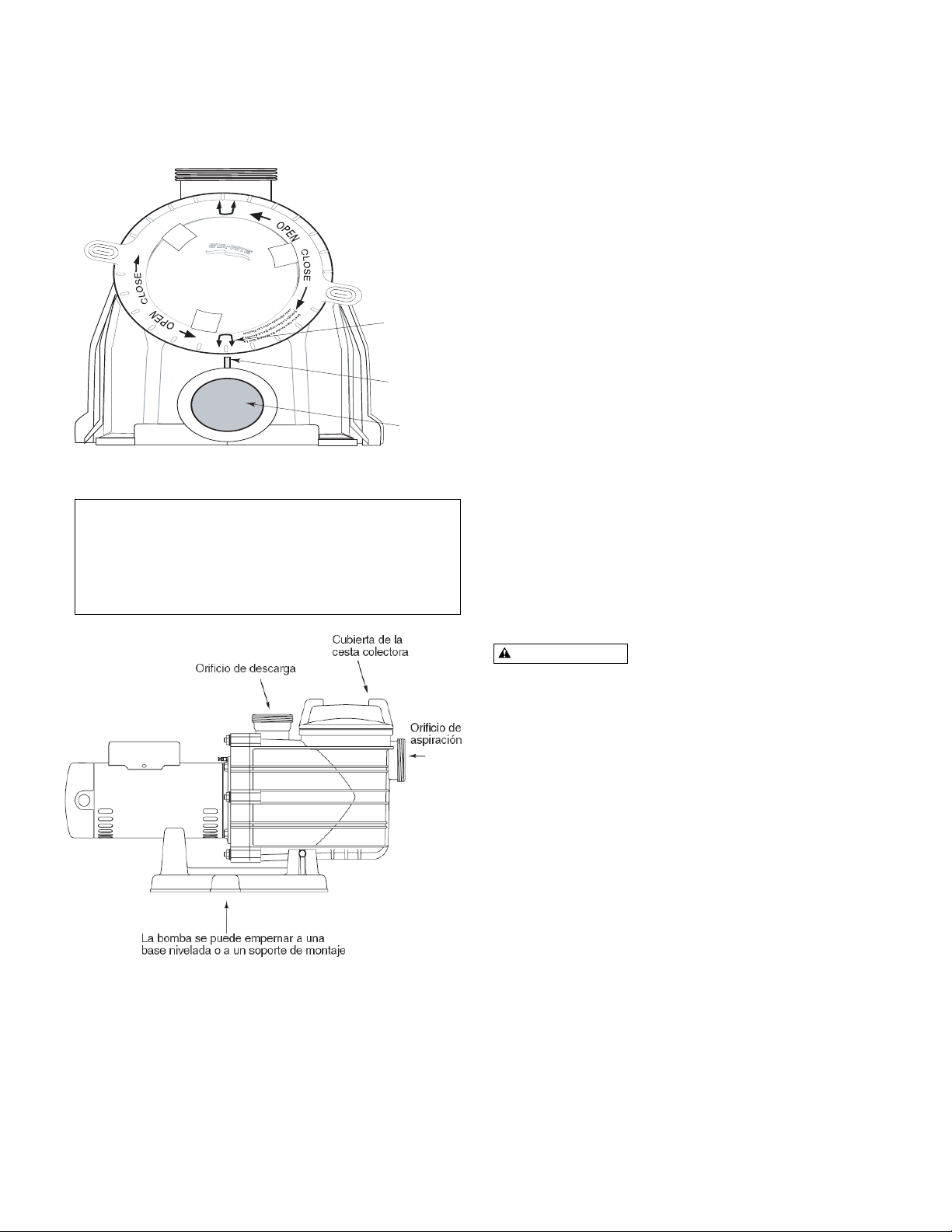
Figura 1. Alineanto del cesto colador
Figura 2
P
P
M
M
U
U
P
P
N
N
S
O
W
O
O
S
R
B
B
R
I
W
I
A
O
R
R
R
N
R
E
O
O
E
A
S
S
W
N
T
E
G
E
G
E
B
N
N
W
I
I
S
T
R
R
E
N
-
-
B
G
I
D
D
S
I
L
I
A
L
N
L
G
E
I
E
E
G
L
T
T
R
A
A
A
A
T
E
T
H
G
O
O
C
R
R
R
S
A
I
H
D
C
S
I
D
Flechas
Etiqueta
Orificio de
descarga
ADVERTENCIA
Page 16

4
Instrucciones para la
aplicación de cinta de Teflón:
Use sólo accesorios para tubos de PVC nuevos o limpios.
Envuelva las roscas macho de
los tubos con una o dos capas
de cinta de Teflón. Cubra toda la
porción fileteada del tubo.
¡No apriete demasiado ni más
allá del tope de rosca en el
orificio de la bomba!
Si observa fugas, saque el tubo,
limpie la cinta vieja, vuelva a
envolverlo con una o dos capas
adicionales de cinta y vuelva a
establecer la conexión.
AVISO: ¡Soporte todos los
caños conectados a la bomba!
Tuberías:
Use un tubo de al menos 2” (51
mm). Aumente el tamaño si
necesita un trayecto largo.
Para evitar demasiado esfuerzo
sobre la bomba, soporte la tubería de aspiración y de
descarga en forma independiente. Coloque estos soportes
cerca de la bomba.
Para evitar el esfuerzo debido a una brecha en la última
conexión, comience toda la tubería en la bomba y haga correr
los caños alejándose de la misma.
Para evitar la creación de bolsas de aire, incline el tubo de
aspiración ligeramente hacia arriba y hacia la bomba.
AVISO: Para impedir inundaciones cuando saque la bomba
para realizar trabajos de mantenimiento o de reparación, todos
los sistemas de aspiración inundados deberán tener válvulas
de compuerta en las tuberías de aspiración y de descarga.
1
Lake Chemical Co., Chicago, Illinois
REQUERIMIENTOS PARA
LA ASPIRACIÓN DE LA
BOMBA
La aspiración de la bomba es peligrosa y puede atrapar,
ahogar o desentrañar a los bañistas. No use ni opere
albercas, jacuzzis, baños termales ni otros sistemas acuáticos,
si observa que las cubiertas de las salidas de aspiración faltan,
están rotas o flojas.
Siga los lineamientos que aparecen a continuación para la
instalación de una bomba, para reducir los peligros a los
usuarios de albercas, jacuzzis, baños termales y otros
sistemas acuáticos.
Protección para no quedar atrapado
El sistema de aspiración de la bomba debe ofrecer protección
contra el peligro de que una persona o su cabello queden
atrapados o enredados debido a la aspiración.
Cubiertas para la salida de aspiración
Es necesario mantener todas las cubiertas de las salidas de
aspiración. Se deberán reemplazar en caso de que estén
rajadas, rotas o ausentes.
Consulte la página 5 para obtener información sobre los
requerimientos de certificación de las cubiertas para las
salidas.
Todas las salidas de aspiración deben contar con cubiertas
debidamente instaladas, y atornilladas en su lugar.
Aspiración peligrosa.
Puede atrapar el cabello
o partes del cuerpo,
provocando lesiones
graves o muerte.
No bloquee
la aspiración.
Figura 2 – Configuración recomendada de la aspiración de la bomba.
Mínimo
3 pies
No hay válvulas entre el Te
y los Drenajes principales
Salida de aspiración
(Drenaje principal)
Bomba
Salida de aspiración
(Drenaje principal)
Válvulas OK entre la
bomba y el Te
Cubierta o Accesorio de
Aspiración anti-enredos,
certificado por IAPMO,
atornillado al colector
del drenaje principal.
Cubierta o Accesorio de
Aspiración anti-enredos,
certificado por IAPMO,
atornillado al colector
del drenaje principal.
PELIGRO
At Least
3 Feet
IAPMO Certified
Anti-entrapment
Cover or Suction Fitting,
screw-fastened to
Main Drain Sump
Suction Outlet
(Main Drain)
Valves OK between
pump and Tee
No valves between
Tee and Main Drains
IAPMO Certified
Anti-entrapment
Cover or Suction Fitting,
screw-fastened to
Main Drain Sump
Suction Outlet
(Main Drain)
Pump
2762 0197
Page 17

5
Salidas de aspiración por bomba (Figura 2)
Proporcione al menos dos drenajes principales hidráulicamente
equilibrados, con cubiertas, como salidas de aspiración para
cada línea de aspiración de la bomba de circulación. Los centros
de los drenajes principales (salidas de aspiración) en cualquiera
de las líneas de aspiración deben estar al menos a tres pies de
distancia entre sí.
Es necesario construir el sistema de manera que no pueda
funcionar si la bomba extrae agua solamente de un drenaje
principal (es decir, que deben haber al menos dos drenajes
principales conectados a la bomba siempre que esté
funcionando – consulte la Figura 2). Sin embargo, si dos
drenajes principales corren hacia una sola línea de aspiración, la
línea de aspiración singular puede estar equipada con una
válvula que cierre ambos drenajes principales desde la bomba
(consulte la Figura 2).
Se puede conectar más de una bomba a una sola línea de
aspiración siempre que se cumplan los requerimientos indicados
en el párrafo que precede.
Velocidad del agua
La máxima velocidad del agua a través del accesorio de
aspiración o de la cubierta para cualquier salida de aspiración
debe ser de 1.5 pies por segundo, a menos que la salida
cumpla con la versión más reciente de la Especificación de
ASME/ANSI para Accesorios de Aspiración que se usen en
Albercas, Jacuzzis, Baños termales, y Piscinas de
Hidromasaje. En todo caso, no sobrepase el caudal máximo
designado para el accesorio de aspiración.
Si el 100% del flujo de la bomba se origina en el sistema de
drenaje principal, la máxima velocidad del agua en el sistema
hidráulico de aspiración de la bomba debe ser de seis pies por
segundo o menos, aún en el caso en que uno de los drenajes
principales (salidas de aspiración) esté completamente
bloqueado.
El flujo a través del (de los) desagüe(s) principal(es)
restante(s) deberá cumplir con la versión más reciente de la
Especificación de ASME/ANSI para Accesorios de Aspiración
que se usen en Albercas, Jacuzzis, Baños termales, y
Piscinas de Hidromasaje.
Pruebas y certificación
Las cubiertas de la salida de aspiración deben haber sido
verificadas por un laboratorio de pruebas reconocido a nivel
nacional, conforme a la versión más reciente de las
Especificaciones de ASME/ANSI para Accesorios de Aspiración
que se usen en Albercas, Jacuzzis, Baños termales, y Piscinas
de Hidromasaje.
Accesorios:
Los accesorios limitan el flujo; para mayor eficacia, use la
mínima cantidad posible de accesorios (pero al menos dos
salidas de aspiración).
Evite accesorios que puedan provocar una trampa de aire.
Los accesorios para albercas deben cumplir con las normas
de la “International Association of Plumbing and Mechanical
Officials (IAPMO)”.
Use solamente accesorios de aspiración que no provoquen
enredos o de doble aspiración.
INFORMACIÓN
ELÉCTRICA
Conecte el motor a tierra antes de conectarlo a la fuente
de corriente eléctrica, de lo contrario existe el peligro de
choque eléctrico grave o fatal.
No haga la conexión a tierra mediante una línea de
suministro de gas.
Para evitar choques eléctricos peligrosos o fatales,
desconecte la alimentación eléctrica al motor antes de
trabajar en las conexiones eléctricas.
El disparo del disyuntor de escape a tierra (“GFCI”
según sus siglas en inglés) indica un problema eléctrico.
Si el GFCI se dispara y no se reposiciona, haga que un
electricista competente inspeccione y repare el sistema
eléctrico. La tensión de suministro debe corresponder
exactamente a la tensión indicada en la placa de fábrica.
Una tensión incorrecta puede provocar incendios o
causar daños considerables al motor y anular la
garantía. En caso de duda, consulte a un electricista
certificado.
Figura 3 – Ubicaciones típicas del tornillo de puesta a
tierra y de la saliente de empalme.
Tornillo
verde de
puesta a
tierra
Saliente de
empalme
Bonding
Lug
Green
Ground
Screw
A
A
230V
115V
L2
L2
L1
L1
Page 18

6
Tensión (voltaje)
La tensión en el motor no debe ser más del 10% superior o
inferior a la tensión nominal indicada en la placa de fábrica, ó
el motor se recalentará, provocando un disparo de la
sobrecarga y reduciendo la vida útil del componente. Si la
tensión es menor del 90% o mayor del 110% de la tensión
nominal cuando el motor esté marchando a toda carga,
consulte con la empresa de energía.
Conexión a tierra/Metalización eléctrica
Instale, conecte a tierra, empalme y conecte los cables del
motor conforme a los requerimientos locales o del “National
Electrical Code”.
Motor con conexión permanente a tierra. Use el borne verde a
tierra suministrado debajo de la cubierta del motor o de la
plancha de acceso (Consulte la Figura 3); use los cables del
tamaño y del tipo requeridos por el código. Conecte el borne
de conexión a tierra del motor a la tierra del servicio eléctrico.
La metalización eléctrica del motor se debe hacer a la
estructura de la alberca. Use un conductor de cobre macizo,
tamaño No. 8 AWG (8.4 mm
2
) o mayor. Haga correr el cable
desde la saliente externa de empalme (consulte la Figura 3) a
la vara o malla de refuerzo.
Figura 4B - Ficha de
cambio de voltaje
configurada para 115
Voltios.
Figura 4A - Ficha de
cambio de voltaje
configurada para 230
Voltios.
TABLA I - INFORMACIÓN SOBRE LOS FUSIBLES Y LOS CABLES RECOMENDADOS
Servicio al motor - distancia en pies (metros)
Tamaño AWG del cable (mm2)
HP Branch fuse Max Load Voltaje/ 0-100' 101-200' 201-300'
Modelo del motor rating amps* Amps Hz/Fase (0-30) (30-60) (60-90)
MPRA6B-202L
1/3 15/15 4.2/2.1 115/230/60/1 14/14(2/2) 14/14(2/2) 12/14(3/2)
1750 RPM
* Se recomienda usar fusibles temporizados en lugar de fusibles estándar en cualquier circuito de motor.
Page 19

7
Conecte un cable de empalme de cobre macizo No. 8 AWG
(8.4 mm
2
) al conector del cable de presión suministrado en la
caja del motor y a todas las partes metálicas de la alberca, el
jacuzzi o el baño termal, y a todo equipo eléctrico, tubería
metálica o conducto dentro de una distancia de 5 pies (1.5 m)
de los muros interiores de la alberca, el jacuzzi o el baño
termal.
Cableado
AVISO: Los modelos trifásicos requieren arranques de motor
magnéticos y protección externa contra sobrecarga. En caso de
duda sobre el procedimiento, consulte a un electricista
certificado.
La bomba debe estar permanentemente conectada al circuito.
La Tabla 1, página 6, indica los tamaños correctos de los
cables y disyuntores para la
bomba sola. Si se conectan
otras luces o aparatos
electrodomésticos al mismo
circuito, asegúrese de agregar
las cargas de amperaje a la
carga de amperaje de la bomba
antes de determinar los tamaños
correctos para los cables y
disyuntores.
(Si no está seguro o está
confundido, consulte a un
electricista certificado.) Use el
disyuntor de carga como
interruptor maestro de
encendido y apagado.
Instale un disyuntor de escape a
tierra (“GFCI”) en el circuito; éste detectará un cortocircuito a
tierra y desconectará la corriente eléctrica antes de que resulte
peligroso para los usuarios de la alberca. Consulte las
instrucciones del fabricante para determinar el tamaño del
GFCI requerido y los procedimientos de verificación del GFCI.
En caso de un corte de corriente, verifique que el GFCI no se
haya disparado (lo cual impediría un funcionamiento normal de
la bomba). Reposicione de ser necesario.
AVISO: Si no usa un conducto para cablear el motor, verifique
que la abertura del cable en el extremo del motor esté cerrada
herméticamente para impedir la entrada de suciedad, insectos,
etc.
Riesgo de choque eléctrico peligroso o
fatal. Verifique que la alimentación eléctrica al circuito del
motor esté desconectada antes de trabajar con los cables, las
conexiones de los cables o con el motor. Vuelva a colocar la
cubierta del motor y las cubiertas de los otros cables antes de
activar la alimentación eléctrica.
1. Desconecte la alimentación eléctrica.
2. Saque la cubierta del motor.
Cómo cablear un motor de una sola velocidad
y un sólo voltaje
Hay dos bornes marcados L1 y L2. Conecte los conductores
de alimentación a estos bornes. Cualquiera de los cables se
puede conectar a cualquier de los bornes.
Cómo cablear un motor de doble voltaje
Los motores de doble voltaje tienen una ficha para cambiar de
230 voltios (graduación de fábrica) a 115 voltios.
1. Si usted tiene una tensión de suministro del motor de 230
voltios, verifique que la ficha esté configurada para 230
voltios. La flecha en la ficha indicará a la posición de 230
voltios. Observe que la ficha sólo se puede conectar con
una de las puntas en esta posición.
2. Si tiene un suministro de 115 voltios, empuje la ficha
directamente hacia arriba y colóquela en las dos puntas de
latón según se ilustra.
NOTA: La flecha está realzada para mayor claridad.
ADVERTENCIA
Aspiración peligrosa.
Puede atrapar el
cabello o partes del
cuerpo, provocando
lesiones graves o
muerte.
No bloquee la
aspiración.
ADVERTENCIA
Page 20
8
OPERACIÓN
AVISO: NUNCA haga marchar la
bomba en seco, ya que eso
puede dañar los sellos,
provocando fugas e
inundaciones. Llene la bomba
con agua antes de encender el
motor.
Antes de
retirar la cubierta del colector:
1. DETENGA LA BOMBA antes
de continuar.
2. CIERRE LAS VÁLVULAS DE
COMPUERTA en las tuberías
de aspiración y de descarga.
3. LIBERE TODA LA PRESIÓN
de la bomba y del sistema de
tubería.
Si la bomba está pasando una prueba de presión,
verifique que se haya liberado la presión antes de retirar
la cubierta del sifón.
No bloquee la aspiración de la bomba. Si se bloquea con
el cuerpo, puede provocar lesiones graves o fatales.
Cuando niños pequeños usen la alberca, es importante que
SIEMPRE estén bajo la estricta supervisión de un adulto.
Peligro de incendio y quemaduras. Los
motores modernos funcionan a altas temperaturas. Para
reducir el peligro de incendio, no permita que hojas,
escombros o partículas extrañas se acumulen alrededor del
motor de la bomba. Para evitar quemaduras cuando se trabaje
con el motor, deje que éste se enfríe durante unos 20 minutos
antes de manipularlo. Un interruptor interno de corte
automático protege al motor contra daños térmicos durante su
funcionamiento.
Cebado de la bomba
Libere toda la presión del filtro, de la bomba y del sistema de
tubería; consulte el manual del propietario.
En un sistema de aspiración inundado (la fuente de agua está
a un nivel más alto que la bomba), la bomba se cebará por sí
misma cuando se abran las válvulas de aspiración y de
descarga.
Si la bomba no está en un sistema de aspiración inundado,
destornille y retire la cubierta del colector (consulte la Figura
5); llene el colector y la bomba con agua.
Limpie e inspeccione el aro tórico, vuelva a colocar la cubierta
del colector.
No lubrique el aro tórico de la cubierta del sifón. El aro tórico
original de la máquina contiene un lubricante interno
permanente.
AVISO: Si reemplaza el aro tórico con uno sin lubricación interna,
es posible que necesite aplicar un lubricante a base de silicona.
Vuelva a colocar la cubierta del colector en el colector; gire hacia
la derecha para apretar la cubierta.
AVISO: ¡Apriete la cubierta del colector a mano solamente (sin
llaves de tuerca)!
Ahora la bomba se deberá cebar. El tiempo de cebado
dependerá del largo vertical de la altura de aspiración y del largo
horizontal de la tubería de aspiración.
Si la bomba no ceba, verifique que todas las válvulas estén
abiertas, que el extremo de la tubería de aspiración se encuentre
debajo del agua, que la bomba no esté tratando de levantar agua
a más de 5 pies (1.5 m) de altura, y que no haya fugas en la
tubería de aspiración. Consulte la Guía para la Localización de
Fallas, Página 11.
Almacenamiento/Preparación para el invierno:
AVISO: ¡Si permite que la bomba se congele, la bomba sufrirá
daños y la garantía quedará anulada!
AVISO: No use soluciones anticongelantes (excepto
propilenglicol) en su sistema de alberca/jacuzzi. El
propilenglicol, “anticongelante RV” no es tóxico y no dañará los
componentes plásticos del sistema, otros anticongelantes son
muy tóxicos y pueden dañar los componentes plásticos en el
sistema.
Drene toda el agua de la bomba y de la tubería cuando espere
temperaturas heladas o cuando guarde la bomba por un
tiempo prolongado (consulte las instrucciones a continuación).
Mantenga el motor seco y cubierto durante el almacenamiento.
Para evitar problemas de
condensación / corrosión, no
cubra la bomba con plástico.
Para instalaciones no protegidas
/ al exterior:
1. Encierre todo el sistema en un
recinto a prueba de la
intemperie.
2. Para evitar daños debido a
condensación / corrosión,
asegúrese de que haya
ventilación; no envuelva el
sistema en plástico.
3. Use una solución de 40%
propilenglicol/60% agua,
para proteger la bomba a
temperaturas de -50° F
(-46° C).
Drenaje de la bomba
Peligro de explosión. La purga del
sistema con aire comprimido puede hacer que explote, con el
peligro de lesiones graves o muerte a cualquiera que se
encuentre cerca. Use sólo un soplador de gran volumen a baja
presión (debajo de 5 PSI), cuando purgue el aire de la bomba,
del filtro o de la tubería.1. Baje el nivel del agua por debajo de
todos los orificios de admisión a la alberca.
Para evitar el riesgo de choques eléctricos peligrosos o
fatales, desconecte la alimentación eléctrica al motor
antes de drenar la bomba.
ADVERTENCIA
Tensión peligrosa.
Puede provocar choques
eléctricos, quemaduras o
muerte.
Desconecte la alimentación
eléctrica antes de trabajar
con la bomba o con el
motor.
Figura 6 – Use una barra o una tabla de apalancar
según se ilustra, para sacar una tapa apretada. No use
una barra de apalancar para apretar la tapa.
ADVERTENCIA
Tensión peligrosa.
Puede provocar choques
eléctricos, quemaduras o
muerte.
Desconecte la alimentación
eléctrica antes de trabajar
con la bomba o con el
motor.
ADVERTENCIA
ADVERTENCIA
ADVERTENCIA
Page 21
9
2. Saque la cubierta del sifón y use aire a baja presión para
soplar el agua acumulada del sistema de tubería. Use una
barra o una tabla de apalancar para sacar las cubiertas del
colectorque estén demasiado apretadas o se hayan
atascado y no se puedan sacar con la mano. La tapa del
colector tiene salientes para poder usar una palanca o una
barra de apalancar (consulte la Figura 6).
3. Tape la tubería de admisión después de drenar para
mantener el agua fuera de los caños.
4. Para impedir que la bomba se congele, saque la cubierta
del colector y drene la unidad del tanque a través de los
dos tapones de drenaje provistos.
A. Drene el sistema lo más posible por gravedad.
B. Proteja las áreas que retienen agua con un
anticongelante de propilenglicol que no sea tóxico
(anticongelante “RV”).
5. Limpie la bomba a fondo y vuelva a colocar la cubierta del
colector.
AVISO: Apriete la cubierta del colector a mano solamente
(¡sin llaves de tuerca)! Si la bomba no está anclada, ¡tenga
cuidado de no romper los caños sujetos a la misma!
6. Asegúrese de que el motor se mantenga seco y cubierto.
Arranque para máquinas preparadas para el
invierno
1. Retire toda protección provisoria contra la intemperie que
se haya colocado alrededor del sistema para el período de
inactividad.
2. Siga las instrucciones del fabricante del filtro para reactivar
el filtro.
3. Inspeccione todos los cables eléctricos y verifique que no
se hayan dañado o deteriorado durante el período de
inactividad. Haga que un técnico de servicio competente
repare todos los cables que así lo requieran.
4. Inspeccione y ajuste todas las conexiones herméticas.
5. Abra todas las válvulas en las tuberías de aspiración y de
regreso.
6. Saque todos los tapones de preparación para el invierno
del sistema de tuberías.
7. Drene todo el anticongelante del sistema.
8. Cierre todas las válvulas de drenaje y reemplace todos los
tapones de drenaje en el sistema de tuberías.
9. Cebe la bomba según las instrucciones que aparecen en
la página 7.
SERVICIO DE LA BOMBA
El servicio de la bomba debe ser realizado solamente por
personas competentes.
Para obtener los mejores resultados, use sólo repuestos
genuinos de fábrica de Sta-Rite.
Asegúrese de cebar la bomba (página 7) antes de encenderla.
Antes de
retirar la cubierta del sifón:
1. DETENGA LA BOMBA
antes de continuar.
2. CIERRE LAS VÁLVULAS DE COMPUERTA en las
tuberías de aspiración y de descarga.
3. LIBERE TODA LA PRESIÓN de la bomba y del sistema de
tuberías.
Para evitar el riesgo de choques eléctricos peligrosos o
fatales, desconecte la alimentación eléctrica al motor
antes de drenar la bomba.
Exceptuando la lubricación del aro tórico de la cubierta del
colector, no se necesita realizar ningún tipo de lubricación y
mantenimiento habitual fuera del cuidado razonable y de la
limpieza periódica de la cesta colectora.Si el sello del eje está
gastado o averiado, repárelo de la siguiente manera:
Desensamblaje de la bomba /
Remoción del sello viejo
Desconecte la alimentación eléctrica al motor de la bomba.
Asegúrese de que las válvulas en las tuberías de
aspiración y de regreso estén cerradas antes de
comenzar a trabajar.
Libere toda la presión abriendo todos los orificios de
ventilación antes de comenzar a trabajar.
1. Drene la bomba, sacando los tapones de drenaje en la parte
inferior de la unidad de la bomba y de la unidad del colector.
2. Verifique que no haya presión en la unidad del colector;
saque la cubierta (destornille girando hacia la izquierda).
3. Saque las 6 tuercas, las arandelas de fijación y las
arandelas planas, sujetando la plancha de estanqueidad a
la unidad de la bomba. Jale y saque la plancha de
estanqueidad y el motor de la unidad de la bomba. (Puede
ser necesario usar un destornillador CUIDADOSAMENTE
para separar la unidad de la plancha de estanqueidad).
4. Saque los siete tornillos y arandelas que sujetan el difusor
a la plancha de estanqueidad. Saque el difusor.
Polished
Figura 8
Superficie pulida
Superficie
de caucho
Figura 7
Sello mecánico asiento de cerámica
Mechanical seal
ceramic seat
surface
PRECAUCIÓN
Rubber
surface
Page 22

10
Clave Descripción MPRA6B-143L
No. de la pieza Cantidad 1/3 HP
1 Motor, 115/230V 1750 RPM 1 62003-2088
2 Tornillo #10-32 x 1/2” 1 U30-692SS
3 Saliente de empalme 1 U17-568
4 Deflector 1 17351-0009
5 Plancha de estanqueidad 1 C3-184P
6 Cordón anular de la plancha de estanqueidad 1 U9-373
7 Sello del eje 1 37400-0027S
8 Impulsor 1 C105-236PDA
8A O-Ring Gasket 1 33455-1047
8B Impeller Screw 1 37337-6080
9 Difusor 1 C1-270P
10 Aro tórico del difusor 1 U9-374
11 Unidad de tanque y colector (solamente) 1 C76-71P
12 Cubierta del colector 1 17307-01111
13 Aro tórico de la cubierta del colector 1 35505-1440
14 Cesta del colector 1 C8-58P
15A Tapón de drenaje 2 U178-920P
15B Tornillo de montaje de 5/16-14 x 5/8” 2 U30-919SS
16 Base 1 C4-77P
17 Cojinete del motor 1 C35-45
18 Tornillo #8-32 x 7/8” cabeza redonda 7 U30-542SS
19 Arandela de fijación #8 diente alargado 7 U43-21SS
20 Arandela plana de 3/8” 6 U43-62SS
21 Arandela de fijación 3/8” 6 U43-12SS
22 Tuerca de 3/8-16 Hexagonal. Latón chapado en níquel 6 71403
23 Tornillos prisioneros de 3/8-16 x 1” Hexagonales 4 U30-74SS
• Placa de fábrica 1 32155-4071
• Etiqueta, “PRECAUCIÓN Esta bomba viene 1 U63-13
equipada con un sello de eje mecánico …”
• Etiqueta de tensión (voltaje) 1 U27-153
• Calcomanía “tapa de sifón demasiado apretada …” 1 U27-644
• Etiqueta, “ADVERTENCIA/PRECAUCIÓN/Instrucciones...” 1 C63-12
• No se ilustra.
LISTA DE PIEZAS PARA REPARACIONES
Paquete 188 con juego de unión de
1/2 corredizo de 2”
Note that this kit includes both inlet
and outlet connections.
Incluye:
Collarín de unión U11-200PS - Qty 2
Aro tórico U9-362 - Qty 2
Adaptador U11-196PS
corredizo de 2” - Qty 2
Cuadro A
24
23
1
2
3
4
22
21
5
20
6
19
15B
Ver Cuadro A
7
8
8A
8B
18
17
16
9
10
11
12
13
14
15A
Ver Cuadro A
Page 23

11
5. Saque el techo del motor. Teniendo cuidado de no tocar los
bornes del capacitor, afloje la abrazadera del capacitor y
muévalo a un lado.
6. Sostenga el eje con una llave abierta de 7/16” en los filos del
eje del motor.
7. Destornille el impulsor del eje (gire hacia la izquierda frente al
mismo).
AVISO: En el modelo de 2 HP, saque el tornillo del impulsor
(rosca izquierda - gire hacia la derecha) y la empaquetadura
antes de sacar el impulsor. Verifique que la empaquetadura
no esté averiada, que no tenga rajaduras, etc. Cámbiela si
está averiada.
8. Saque los cuatro tornillos que sostienen la plancha de
estanqueidad al motor.
9. Coloque la plancha de estanqueidad boca abajo sobre una
superficie plana y golpetee el asiento de cerámica para
sacarlo (Figura 7).
10. Saque el deflector del eje del motor y verifique que no esté
averiado ni tenga abrasión.
11. Limpie la cavidad del sello en la plancha de estanqueidad y
limpie el eje del motor.
Re-ensamblaje de la bomba /
Instalación de un sello nuevo
1. El asiento de cerámica debe estar limpio y sin suciedad,
grasa, polvo, etc. Humedezca el borde exterior con una
pequeña cantidad de detergente líquido, oprima el asiento de
cerámica en la cavidad de la plancha de estanqueidad
firmemente haciendo presión con el dedo (Figura 8).
2. Si el asiento de cerámica no encaja debidamente, sáquelo,
colóquelo boca arriba sobre un banco y vuelva a limpiar la
cavidad. El asiento de cerámica ahora deberá encajar
debidamente.
3. Si el asiento aún no encaja debidamente, coloque una
arandela de cartón sobre la superficie pulida y use un trozo
de caño estándar de 3/4” (19 mm) para hacer presión.
AVISO: Asegúrese de no rayar ni estropear la superficie o el
sello goteará.
4. Reemplace el deflector en el extremo del eje del motor de
manera que el manguito del impulsor lo empuje en posición.
Si se observan señales de desgaste o avería en el deflector,
cámbielo.
5. Vuelva a instalar la plancha de estanqueidad en el motor.
Apriete los pernos a una torsión de 60-80 pulgada/libra
(69-92 kg/cm).
6. Aplique una pequeña cantidad de detergente líquido en el
diámetro interior de la mitad giratoria del sello.
7. Deslice la unidad giratoria del sello, con la superficie de carbón
hacia afuera, sobre el manguito del impulsor hasta que el aro
accionador de caucho toque la parte posterior del impulsor.
AVISO: Asegúrese de no cortar ni rayar la superficie pulida
del sello, ya que el sello goteará con una superficie dañada.
8. Atornille el impulsor en el eje (hacia la derecha); esto colocará
el sello automáticamente en la plancha de estanqueidad.
AVISO: En los modelos de 2 y 2-1/2 HP, instale la
empaquetadura del impulsor y el tornillo de sujeción (rosca
izquierda - gire hacia la izquierda). La torsión del tornillo de
sujeción debe ser de 50-55 pulgada/libra (57.6-63 kg/cm).
9. Monte el difusor sobre la plancha de estanqueidad;
apriete los tornillos a una torsión de 10-14 pulgada/libra
(11.2-16.1 kg/cm).
10. Ensamble el motor y la plancha
de estanqueidad a la unidad de la
bomba con tuercas, arandelas
planas y arandelas de
fijación. La torsión de las tuercas
debe ser de 120-130
pulgada/libra (138-150 kg/cm).
11. Cebe la bomba según las
instrucciones que aparecen en la
página 7.
GUÍA DE
LOCALIZACIÓN
DE FALLAS
¡Es importante leer y
comprender las instrucciones
de seguridad y de operación en este
manual antes de realizar trabajos en
la bomba!
¡Las pruebas eléctricas del
motor de esta bomba deben ser
realizadas solamente por personas competentes!
NO BOMBEA; CAPACIDAD O PRESIÓN DE DESCARGA
REDUCIDA
Fugas en la aspiración / pérdida de cebadura:
1. Es necesario cebar la bomba; verifique que la voluta y el
colector de la bomba estén llenos de agua. Consulte las
instrucciones de cebadura, Página 7.
2. Verifique que no haya fugas en la tubería de aspiración.
3. Verifique que la admisión de la tubería de aspiración esté
bien por debajo del nivel del agua para impedir que la bomba
aspire aire.
4. Si la empaquetadura del colector de aspiración es
defectuosa, cámbiela.
5. Verifique que la bomba no esté tratando de levantar agua a
una altura mayor de 10’ (3 m).
6. Verifique que la tubería de aspiración tenga un diámetro
mínimo de 2” (51 mm).
Tubería/colector/impulsor tapado, impulsor gastado:
7. Verifique que el colector de aspiración no esté tapado, de lo
contrario, limpie el colector y el colador.
8. Verifique que impulsor no esté tapado (siga los pasos 1 al 7
en la sección “Remoción del sello viejo”, Página 9; verifique
que el impulsor no esté tapado; siga los pasos 7 al 11 en la
sección de “Instalación del nuevo sello”, Página 9, para reensamblar).
9. Es posible que el Impulsor y el difusor estén gastados. De
ser así, encargue piezas de repuesto de la Lista de Piezas
para Reparaciones, página 10.
ADVERTENCIA
Tensión peligrosa.
Puede provocar choques
eléctricos, quemaduras o
muerte.
Desconecte la alimentación
eléctrica antes de trabajar
con la bomba o con el
motor.
Page 24

Soporte Técnico
Sanford, North Carolina (8 A.M. a las 5 P.M. Horario del Este y Pacifico)
Moorpark, California (8 A.M. a las 5 P.M. Horario del Este y Pacifico)
Phone: (800) 831-7133
Fax (800) 284-4151
Pagina de internet: visite www.pentairpool.com y staritepool.com
S752 Rev B (10-07-09)
 Loading...