

Page 1
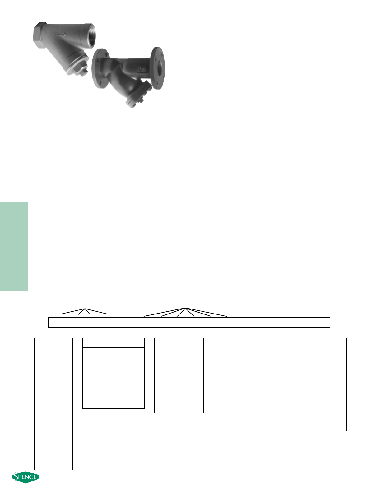
125Y SERIES
STRAINERS
125Y SERIES
BRONZE, CAST IRON Y STRAINERS
NPT, SWEAT ENDS, FLANGED
PRESSURES TO 200 PSIG (13.8 BARG)
T
EMPERATURES TO 450°F (232°C)
●ANSI 125# rated strainers
●NPT, SE and FF flanges in accordance with ASME 16.1
and 16.15
●One piece cast body
●Upper and lower machined seats
●Generous screen area and properly proportioned
straining chamber to minimize intial pressure drop
while maximizing time between cleanings.
MODELS
●125Y1T - Bronze, NPT, Threaded Cover
●125Y1E - Bronze, Sweat Ends, Threaded Cover
●125Y2F - Cast Iron, Flanged, Bolted Cover
- 384 -
0100-125Y1TB- A2__
12345678910111213141516
Inlet Size Model
Add’l
Dash
Body Dash Perf
Mesh
Require-
Material ments
125Y Series Ordering Code
Dash - Position 5
Model - Position 6 - 11
125Y1T
125Y1E
125Y2F
Body Material -
Position 12
I - Cast Iron
B - Bronze
Dash - Position 13
Mesh
1, 2
- Position 15
Leave Blank If Not
Required (std Y2F)
1 - 10
2 - 20
3 - 30
4 - 40
5 - 50
6 - 60
7 - 80
8 - 100
9 - 120
Add’l Requirements -
Position 16
Leave Blank
If not Required
D - Special Drain Size
F - Silicon Free
G - Special Gaskets
T - Special Testing
X - Oxygen Cleaning
Y - Other and / or
Multiple Specials
Indicate Specials
Clearly On the Order
1. Standard Screens: Y1T, Y1E—20 mesh,
Y2F< 3"—3/64" perf, Y2F>3"—1/8" perf
2. For other screen materials contact factory.
APPLICA TIONS
●Steam, liquid, gas and oil service
●Power industry
●Pulp and paper
●Chemical industry
●Metal & Mining
●Water & Waste
OPTIONS
●Other perforated screens and mesh liners
●Other drain connections and gasket materials
●Oxygen cleaning
●Special internal/external coatings and linings
●Contact factory for other options
APPLICABLE CODES
●ANSI B16.1
● ANSI B16.15
Canadian Registration OEO591.9C for CI 125Y2F
Inlet Size -
Position 1 - 4
0038 -
3
⁄8"
0050 - 1⁄2"
0075 -
3
⁄
4"
0100 - 1"
0125 - 1
1
⁄4"
0150 - 11⁄2"
0200 - 2"
0250 - 2
1
⁄
2"
0300 - 3"
0400 - 4"
0500 - 5"
0600 - 6"
0800 - 8"
1000 - 10"
1200 - 12"
1400 - 14"
1600 - 16"
Perf1- Position 14
304 SS Material
2
A -No Perf
1 - 1/32"
B -3/64"
4 - 1/8"
5 - 3/32"
6 - 3/16"
7 - 7/32"
8 - 1/4"
9 - 3/8"
Page 2
- 385 -
125Y SERIES
STRAINERS
Connections:
3/8" – 3" NPT or Sweat Ends
SCREEN OPENINGS
STANDARD
SIZE SCREEN MATERIALS
3/8" – 3" 20 Mesh 304 SS
125Y1 SERIES
BRONZE Y STRAINERS
NPT, SWEAT ENDS
S
PECIFICATION
Y Strainer shall be straight flow design with NPT or Sweat Ends inlet/outlet
connections. The strainer shall be rated to ANSI 125 PSIG rating in
accordance with ANSI B16.15. The Strainer shall be bronze body and the
screen shall be size ______ mesh 304 SS. The strainer shall be have an
inlet size of ______ and Open Area Ratio of _______. The Y Strainer shall
be SSI 125Y1 Series.
MATERIALS OF
CONSTRUCTION
Body ……………………………………………………Bronze B584
Cover ……………………………………………………Bronze B584
Screen1…………………………………………………304 SS Mesh
Plug………………………………………………………Bronze B584
Gasket1…………………………………………………Garlock 2900
1. Recommended Spare Parts
SIZE A B C E WEIGHT
3
⁄
8 3
1
⁄
4 2
1
⁄
8 3
1
⁄
2
3
⁄
8 .8
(10) (82) (55) (89) (10) (.36)
1
⁄
2 3
1
⁄
4 2
1
⁄
8 3
1
⁄
2
3
⁄
8 1.0
(15) (82) (55) (89) (10) (.25)
3
⁄
4 42
3
⁄
4 4
1
⁄
2
3
⁄
8 1.2
(20) (100) (70) (114) (10) (.60)
14
1
⁄
2 35
1
⁄
2 1.6
(25) (115) (75) (127) (15) (.73)
11⁄4 53⁄8 39⁄16 53⁄4
1
⁄2 2.5
(32) (136) (90) (146) (15) (1.1)
11⁄2 65⁄16 37⁄8 63⁄8
1
⁄2 3.4
(40) (160) (98) (162) (15) (1.6)
27
1
⁄2 57⁄16 91⁄16
1
⁄2 5.8
(50) (191) (138) (230) (15) (2.6)
21⁄2 91⁄16 515⁄16 10
1
⁄2 10.2
(65) (230) (151) (254) (15) (4.6)
310
3
⁄16 65⁄16 103⁄8
1
⁄2 13.7
(80) (259) (160) (264) (15) (6.2)
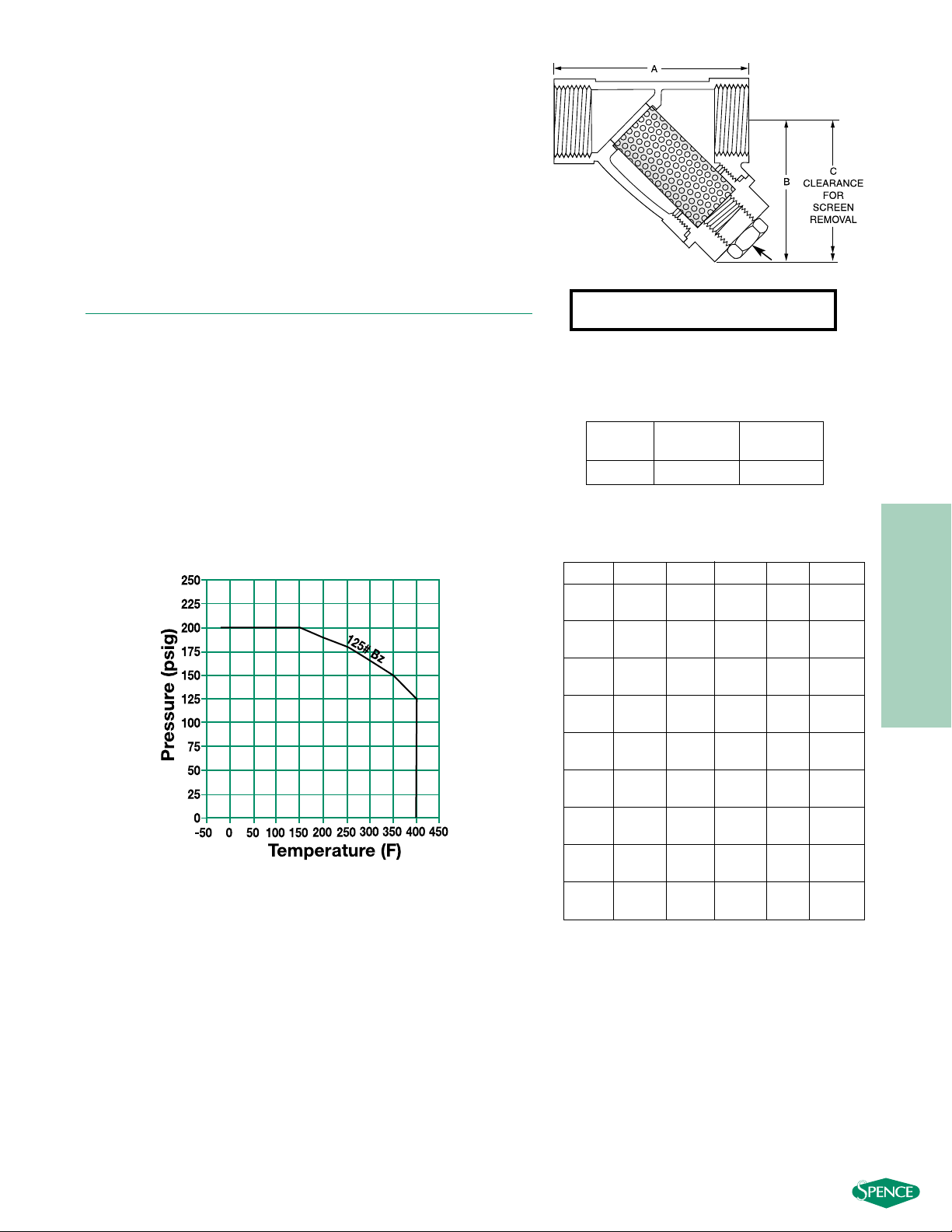
DIMENSIONS inches (mm)
AND WEIGHTS pounds (kg)
Dimensions shown are subject to change. Consult
factory for certified drawings when required.
PRESSURE/TEMPERATURE CHART
ANSI B16.15
E-NPT
Note: For Buttweld sizes please indicate pipe
schedule on the order.
Page 3

- 386 -
125Y SERIES
STRAINERS
Connections:
2" – 16" FF Flanged
SCREEN OPENINGS
STANDARD
SIZE SCREEN MATERIALS
2" – 3" 3/64" Perf 304 SS
4" – 16" 1/8" Perf 304 SS
125Y2 SERIES
CAST IRON Y STRAINERS FLANGED
SPECIFICATION
Y Strainer shall be straight flow design with FF Flanged inlet/outlet
connections. The strainer shall be rated to ANSI 125 PSIG rating in
accordance with ANSI B16.1. The Strainer shall be Cast Iron body and
the screen shall be size ______ perforated 304 SS. The strainer shall be
have an inlet size of ______ and Open Area Ratio of _______. The Y
Strainer shall be SSI 125Y2 Series.
MATERIALS OF
CONSTRUCTION
Body ………………………………………………Cast Iron A126-B
Cover ………………………………………………Cast Iron A126-B
Screen1…………………………………………………………304 SS
Plug …………………………………………………Cast Iron A126-B
Gasket1………………………………………………………Graphite
Bolt/Stud2………………………………………………………A307-B
Nut2………………………………………………………………A563
1. Recommended Spare Parts
2. Materials of equivalent strength may be substituted
SIZE A B C D E WEIGHT
28
7
⁄8 61⁄8 81⁄2 2
1
⁄2 22
(50) (226) (156) (216) (51) (15) (10)
21⁄2 103⁄4 81⁄16 111⁄4 21⁄2 135
(65) (273) (205) (286) (64) (25) (16)
311
5
⁄8 81⁄2 121⁄4 3143
(80) (295) (216) (311) (76) (25) (20)
413
7
⁄8 95⁄8 133⁄8 4175
(100) (353) (245) (340) (102) (25) (34)
516
3
⁄8 115⁄8 161⁄8 51
1
⁄4 115
(125) (416) (295) (410) (127) (32) (52)
618
1
⁄2 125⁄8 1711⁄16 61
1
⁄2 154
(150) (470) (321) (449) (152) (40) (70)
821
3
⁄8 163⁄8 23 8 11⁄2 243
(200) (543) (416) (584) (203) (40) (110)
10 26 191⁄8 2611⁄16 10 2 390
(250) (660) (486) (678) (254) (50) (117)
12 30 221⁄16 31 12 2 650
(300) (762) (559) (787) (305) (50) (295)
14 373⁄8 3011⁄16 41 14 2 815
(350) (949) (780) (1041) (356) (50) (370)
16 421⁄2 331⁄16 46 16 2 1224
(400) (1080) (840) (1168) (406) (50) (555)
DIMENSIONS inches (mm)
AND WEIGHTS pounds (kg)
Dimensions shown are subject to change. Consult factory for
certified drawings when required.
PRESSURE/TEMPERATURE CHART
ASME B16.1
C
A
D
B
Page 4

- 387 -
125Y SERIES
STRAINERS
125Y SERIES BRONZE, CAST IRON
PRESSURE DROP VS FLOW RATE
Water Service, Clean Basket, 1/32" - 1/4" Perforated Screen*
(Sizes 3⁄8
" - 1
1
⁄2
")
* For Gas, Steam or Air service, consult factory.
(Sizes 2" - 16")
Steam Service Pressure Drop
Page 433
Correction Factors for Other Viscous
Liquids and/or Mesh Liners Page 432
Correction Factors for
Clogged Screens Page 432
10
1
PRESSURE DROP (PSIG)
0.1
0.1 1 10 100
3/8”
FLOW RATE (GPM)
1/2”
”
1-1/4
1-1/2”
3/4”
1”
10
14”
16
”
1
PRESSURE DROP (PSIG)
0.1
2-1/2”
3”
4”
5”
6”
8”
2”
10
”
12”
10 100 1000 10000
FLOW RATE (GPM)
 Loading...