

Page 1
DOUBLE DOOR
CHECK VALVES
- 178 -
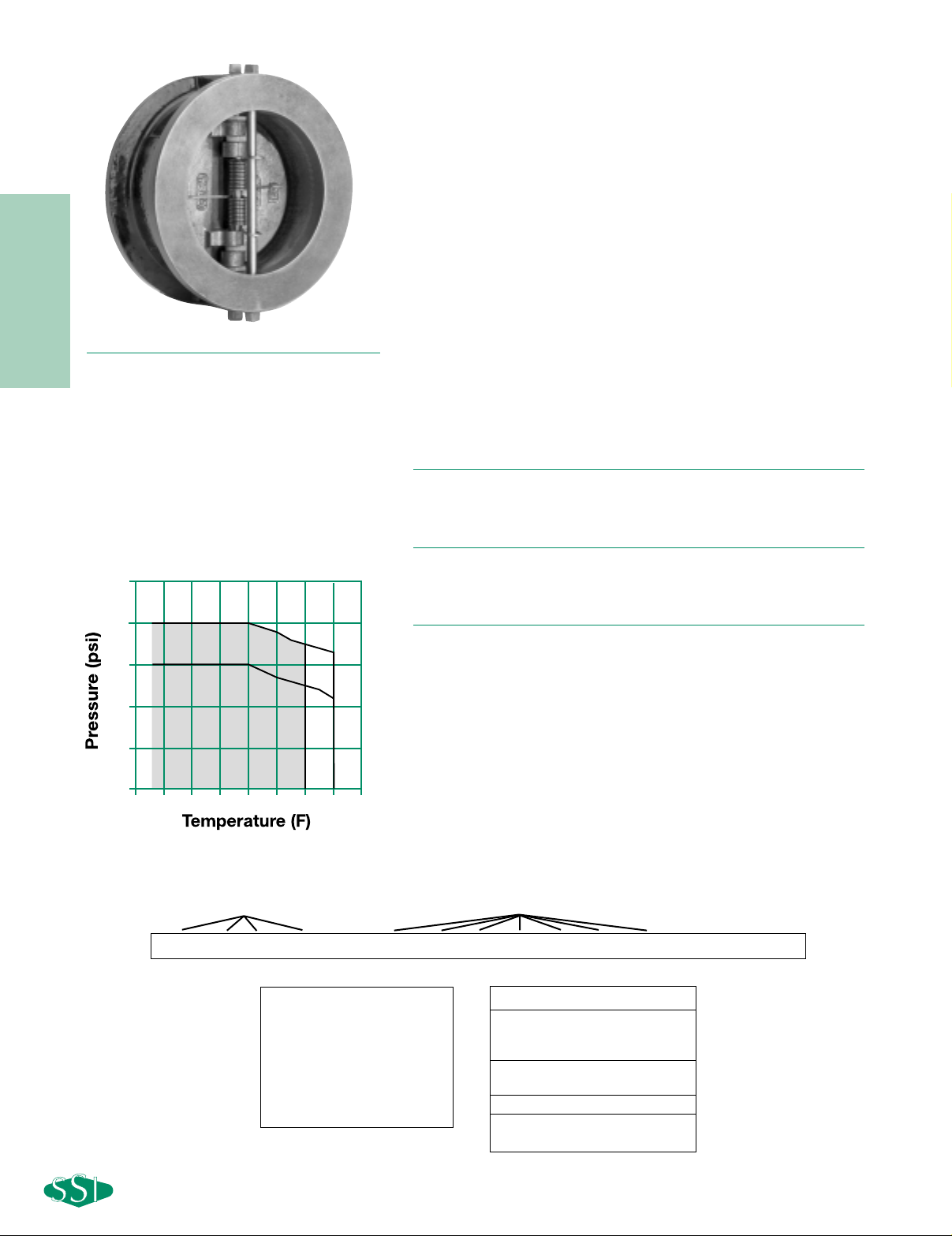
PRESSURE/TEMPERATURE CHART
ASME B16.1
●
ASME Class 125 rated Check Valves
● Wafer body style fits between FF or RF flanges
● Teflon thrust washers
● Resilient Buna-N seats
● Seat design lifts then swings discs to minimize seat
wear
● Independent springs optimizes valve plate closing
rates while minimizing spring stress
● Lifting lug tap on all valves 6" and larger
MODELS
● 125WTIB - Cast Iron Body, Bronze Disc, Buna Seat
● 125WTIT – Cast Iron Body, Stainless Steel Disc, Buna Seat
OPTIONS
● EPDM Seats
● Other Spring Material
A
PPLICABLE CODES
●ASME Sec VIII and B16.1 Bodies
● API 598
● FM approved 30246911 (2"-10" only)
Canadian Registration - OE10274.5C
125WT SERIES
CAST IRON
DOUBLE DOOR CHECK VALVES
PRESSURES TO 200 PSIG (13.8 BARG)
T
EMPERATURES TO 250ºF (121ºC)
APPLICA TIONS
● Liquid and Air Service
● Process Industry
● Power Industry
● Chemical Industry
● Oil & Gas
● Pulp & Paper
● Metal & Mining
● Water & Waste
1000-125WTIBB-T
123456789101112131415
Inlet Size Model Seat Dash Spring
125WT Series Ordering Code
Inlet Size - Position 1 - 4
0200 - 2"
0250 - 2
1
⁄2"
0300 - 3"
0400 - 4"
0500 - 5"
0600 - 6"
0800 - 8"
Dash - Position 5
Model - Position 6 - 12
125WTIB - CI Body, Bz Disc
125WTIT - CI Body, SS Disc
Seat - Position 13
B - Buna-N
Dash - Position 14
Spring - Position 15
T - SS
1000 - 10"
1200 - 12"
1400 - 14"
1600 - 16"
1800 - 18"
2000 - 20"
2400 - 24"
250
200
150
100
50
0
-50
125# CI 2”-12”
125# CI 12”-24”
Buna Seats
EPDM Seats
150100500
200
250
300 350
Page 2
DOUBLE DOOR
CHECK VALVES
- 179 -
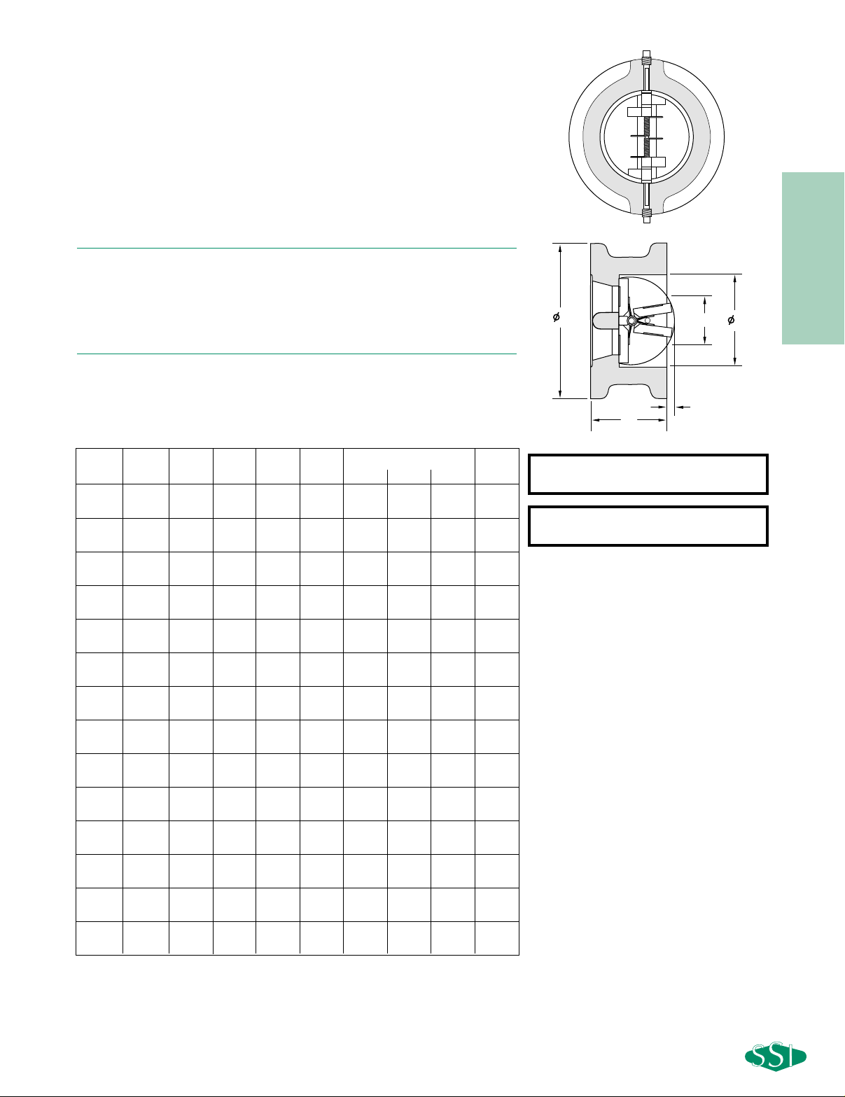
Connections: 2" to 24"
FF Wafer Flanged
125WT SERIES
CAST IRON DOUBLE DOOR CHECK VALVES
SPECIFICATION
Check Valve shall be dual disc design with Cast Iron wafer body style designed to
ASME B16.1 and/or ASME Sec. VIII. The check valve shall have an integral cast
bumper and Buna-N resilient seat with bronze of SS discs. The check valve shall
be ASME Class 125 rated. The spring shall be 316SS. The check valve shall be
SSI 125WT Cast Iron Series.
M
ATERIALS OF CONSTRUCTION
Body ………………………………………………………A126-B Cast Iron
Discs……………………………Al/Bz B148 C954 or 316SS A351-CF8M
Seat …………………………………………………………………Buna-N
Spring …………………………………………………………………316SS
C
RACKING PRESSURE
Horizontal Mounting - .3psid
Vertical Mounting - .75 to 1.25 psid
Seats: 2" to 24"
Buna-N All
Size A B
*
C
1
DE
STUD SELECTION
Weight
Qty. Dia. Length
22
1
⁄8 41⁄8 22
3
⁄8 1/8 4 5/8 51⁄2 3
(50) (54) (105) (51) (60) (3) (16) (140) (1.4)
2.5 21⁄8 47⁄8 21⁄2 27⁄8 1/2 4 5/8 6 5
(65) (54) (124) (64) (73) (13) (16) (152) (2.3)
32
1
⁄4 53⁄8 33
1
⁄2 5/8 4 5/8 61⁄4 8
(80) (57) (137) (76) (89) (16) (16) (159) (3.6)
42
1
⁄2 67⁄8 44
1
⁄2 1 8 5/8 61⁄4 13
(100) (64) (175) (102) (114) (25) (16) (159) (5.9)
52
3
⁄4 73⁄4 55
1
⁄2 11⁄4 8 3/4 7 16
(125) (70) (197) (127) (140) (32) (19) (184) (7.3)
638
3
⁄4 66
5
⁄8 15⁄8 8 3/4 8 20
(150) (76) (222) (152) (168) (41) (19) (203) (9.8)
83
3
⁄4 11 8 85⁄8 23⁄8 8 3/4 91⁄2 37
(200) (95) (279) (203) (219) (60) (19) (241) (16.8)
10 41⁄4 133⁄8 10 103⁄4 3 12 7/8 101⁄2 57
(250) (108) (340) (254) (273) (76) (22) (267) (25.9)
12 55⁄8 161⁄8 12 123⁄4 37⁄8 12 7/8 121⁄4 93
(300) (143) (410) (305) (324) (99) (22) (311) (42.2)
14 71⁄4 173⁄4 121⁄2 14 4 12 1 13 205
(350) (184) (451) (318) (356) (102) (25) (330) (93.1)
16 71⁄2 201⁄4 15 16 51⁄4 16 1 131⁄2 271
(400) (191) (514) (381) (406) (133) (25) (343) (123.0)
18 8 215⁄8 17 18 6 16 11⁄8 141⁄2 310
(450) (203) (549) (432) (457) (152) (29) (368) (140.7)
20 83⁄8 237⁄8 19 20 67⁄8 20 11⁄8 151⁄4 377
(500) (213) (606) (483) (508) (175) (29) (387) (171.2)
24 83⁄4 281⁄4 223⁄4 24 81⁄4 20 11⁄4 161⁄4 551
(600) (222) (718) (578) (610) (210) (32) (413) (250.2)
DIMENSIONS inches (mm) AND WEIGHTS pounds (kg)
Dimensions are subject to change. Consult factory for certified drawings when required.
* Add the “B” dimensions and the diameter of the stud to achieve the ANSI B16.1 bolt
hole circle diameter.
1. Minimum bore diameter of companion flanges
B
DC
A
E
Page 3

DOUBLE DOOR
CHECK VALVES
- 180 -
125WT SERIES DOUBLE DOOR CHECK VALVES
C
AST IRON
Valve Size
(inches)
221⁄2 345 6 8 101214161820 24
C
v
60 100 170 340 520 850 1600 2400 3800 4400 5800 7500 9800 15000
10
100 1000 10000 100000
FLOW RATE (GPM)
PRESSURE DROP (PSID)
6
10
1
0.1
HORIZONTAL MOUNTED
VALVE CRACKING PRESSURE
8
10
12
14
16
18
20
24
5
4
3
2-1/2
2
(1) Pressure drop curves are based on water flow.
(2) Valve cracking pressure is equal to or less than 0.3 psid when mounted horizontally.
(3) Valve cracking pressure increases to between 0.75 and 1.25 psid when installed
vertically with flow upwards.
CVV
ALUES
(US-GPM @ 1 PSID)
PRESSURE DROP - AIR
Sizes 2" - 24"
(1) Pressure drop curves are based on air flow at 60 0F and 1 ATM pressure.
(2) Valve cracking pressure is equal to or less than 0.3 psid when mounted horizontally.
(3) Valve cracking pressure increases to between 0.75 and
1.25 psid when installed vertically with flow upwards.
Installation Note:
1) For correct installation and maintenance please see our I&M manual.
2) Horizontal installation – Disc pin
must be installed in vertical position.
3) Vertical installation (downward flow)
– Consult factory.
PRESSURE DROP - LIQUIDS
Sizes 2" - 24"
10
4
2
1
PRESSURE DROP (PSID)
3
2-1/2
5
6
HORIZONTAL MOUNTED
8
10
VALVE CRACKING PRESSURE
0.1
100
1000 10000 100000 1000000
FLOW RATE (GPM)
12
14
16
20
18
24
 Loading...