

Page 1
PUMP
PROTECTION
- 168 -
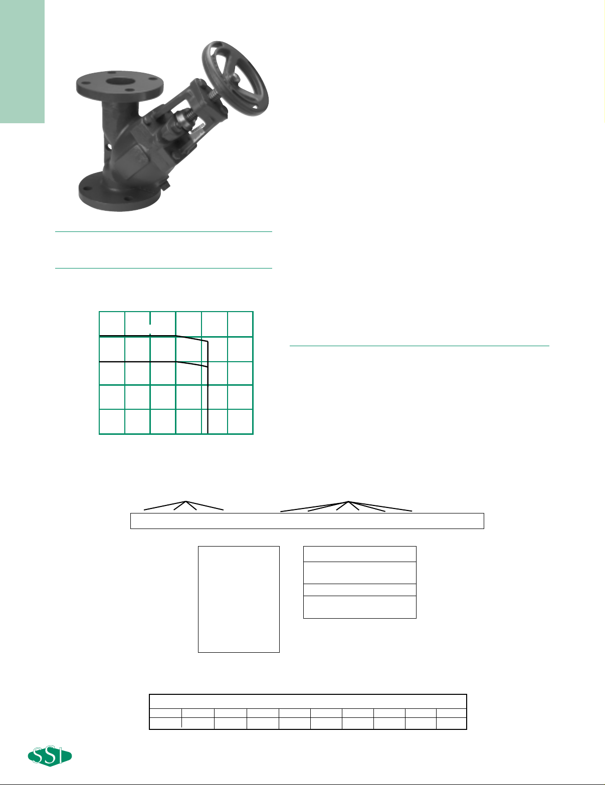
125T SERIES
CAST IRON TRIPLE DUTY VALVES
Pressures to 200 PSIG (13.8 barg)
Temperatures to 212°F (100°C)
● Triple function includes a spring loaded silent
check valve, balancing valve and shutoff valve
to minimize cost and reduce installation time
● Operates automatically and silently
● Center guided soft seal disc ensures leak
free performance
● Spring loaded Buna N disc provides no impact
shutoff and prevents water hammer upon
closing
●Graduated position indicator provides accurate
visual check of valve position
●Standard handwheel for ease of operation
●Cracking pressure of 1/4 PSI
●Drain and differential connections with plug are
furnished as standard
MODELS
●125TFI – Cast Iron Triple Duty Valve
PRESSURE/TEMPERATURE CHART
0400 -125TFI-B
Triple Duty Valve Ordering Code
1 2 3 4 5 6 7 8 9 10 11 12 13
Size Dash Model Dash O-Ring
Size - Position 1-4
0200 - 2”
0250 - 2
1
⁄2”
0300 - 3”
0400 - 4”
0500 - 5”
0600 - 6”
0800 - 8”
1000 - 10”
1200 - 12”
Dash - Position 5
Model - Position 6 -11
125TFI - Triple Duty Valve
Dash - Position 12
O-Ring - Position 13
B - Buna N
For any variations, use the part numbering system above but clearly indicate the additional requirement.
Valve Size
2 2-1/2 3 4 5 6 8 10 12 14
83 129 189 335 529 766 1372 2154 3106 4016
MAXIMUM RATED FLOW COEFFICIENTS (Cv)*
* Maximum Cv rating is at 100% of stem rise.
APPLICA TIONS
●Pump protection
APPLICABLE CODES
(Designed in accordance with)
●ASME B16.1
250
200
150
2"-12"
14"
100
50
Buna N
Pressure (psig)
0
0 50 100 150 200 250 300
Temperature (F)
Page 2
PUMP
PROTECTION
- 169 -
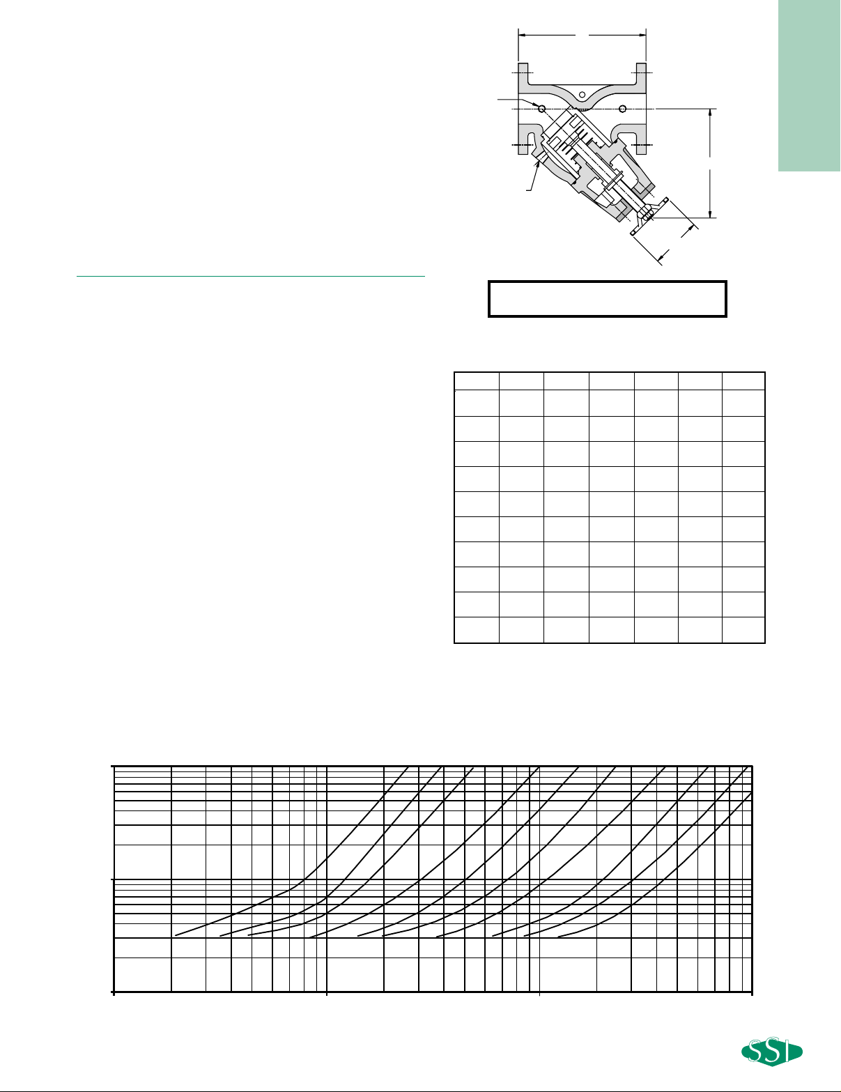
DIMENSIONS inches (mm)
AND WEIGHTS pounds (kg)
Size A B C D E Weight
28
3
⁄
8 9
5
⁄
8 6
5
⁄
16 1/2 1/4 34
(50) (213) (244) (159) (15) (8) (15)
21⁄
2 9
13
⁄
16 10 6
5
⁄
16 1/2 1/4 40
(65) (250) (254) (159) (15) (8) (18)
31010
1
⁄
8 9
3
⁄
8 1/2 1/4 50
(80) (254) (257) (238) (15) (8) (23)
414
1
⁄
2 12
5
⁄
8 9
3
⁄
8 1/2 1/4 100
(100) (368) (321) (238) (15) (8) (45)
51616
3
⁄
8 11 1/2 1/4 155
(125) (407) (416) (279) (15) (8) (70)
61817
1
⁄
2 11 3/4 1/4 200
(150) (457) (444) (279) (20) (8) (91)
821
1
⁄
2 18
1
⁄
2 12
1
⁄
2 3/4 1/4 350
(200) (546) (470) (317) (20) (8) (159)
10 251⁄
2 21
11
⁄
16 12
1
⁄
2 1 1/4 480
(250) (648) (552) (317) (25) (8) (218)
12 30 241⁄
2 12
1
⁄
2 1 1/4 660
(300) (762) (622) (317) (25) (8) (299)
14 303⁄
8 24
1
⁄
2 12
1
⁄
2 1 1/4 790
(350) (771) (622) (317) (25) (8) (359)
Connections:
2" - 14" FF Flanged
125T SERIES
CAST IRON TRIPLE DUTY VALVES
SPECIFICATION
Triple Duty Valve shall install in a straight run of pipe and perform
as a center guided silent check valve, shutoff valve and balancing
valve. The valve shall have ______ psi cracking pressure. The
valve shall have Cast Iron ASME Class 125 FF flanges. The seat
shall have Buna N O-ring seals. The valve shall be an inlet size of
______ and a Cv rating of ______ . The Triple Duty Valve shall be
SSI T Series.
MATERIALS OF C
ONSTRUCTION
Body & Yoke ……………………………Cast Iron A126-B
Disc Guide ………………………Ductile Iron/Nickel Plate
Disc ……………………………………………Ductile Iron
Packing Gland …………………………………Ductile Iron
Packing ……………………………………………Graphite
Spring ………………………………………Stainless Steel
Stem …………………………………………Stainless Steel
Seat Seal ……………………………………………Buna N
Disc Seal ……………………………………………Buna N
Dimensions and Weights are appr oximate. Contact factory for
Certified Drawings.
Dimensions shown are in full open position.
PRESSURE DROP VS FLOW RATE
A
B
C
D
E
(NPT)
(Sizes 2" - 14")
10
1
PRESSURE DROP (PSID)
0.1
10
2"
100
3"
2.5"
FLOW RATE (GPM)
5"4"
1000
10" 12" 14"8"6"
10000
 Loading...