

Page 1
FLANGED SILENT
CHECK VALVES
- 210 -
125FC SERIES
CAST IRON FLANGED
SILENT CHECK VALVES
Pressures to 200 PSIG (13.8 barg)
Temperatures to 300ºF (149ºC)
●ASME Class 125 rated check valve
● Designed to reduce surge and water hammer
● Silent, non-slam closure
● Center guided at both ends to prevent binding
and cocking
● Flanged body style
● Bronze Metal to Metal Seats
● Designed to reduce Water Hammer
MODELS
● 125FCIB - Cast Iron Body, Bronze Seat and Disc
O
PTIONS
(Consult factory)
● Other Spring Material
● Heavier or Lighter Springs
APPLICABLE
CODES
●Bodies in accordance with ASME B16.1
● API 598
Canadian Registraton - OC10274.5C
APPLICA TIONS
●Liquid Service
● Process Industry
● Power Industry
● Chemical Industry
● Oil & Gas
● Pulp & Paper
● Metal & Mining
● Water & Waste
0 8 0 0 - 1 2 5 F C I B M - T
123456789101112131415
Inlet Size
Model
Dash Seat Dash Spring
125FC Series Ordering Code
Dash - Position 5
Model - Position 6 - 12
125FCIB - CI Body, Bz Disc
Seat - Position 13
M - Metal
Dash - Position 14
Spring - Position 15
T - Stainless Steel
Inlet Size - Position 1 - 4
0200 - 2"
0250 - 21⁄2"
0300 - 3"
0400 - 4"
0500 - 5"
0600 - 6"
0800 - 8"
1000 - 10"
1200 - 12"
1400 - 14"
1600 - 16"
1800 - 18"
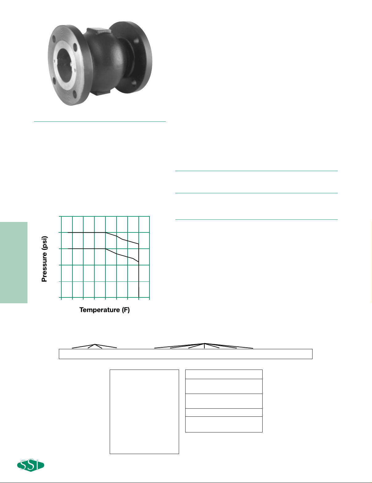
PRESSURE/TEMPERATURE CHART
ASME 16.1
250
200
125# CI 2”-12”
0
-50
125# CI 14”-18”
150
100
50
EPDM O-Ring
150100500
200
250
300 350
Page 2
FLANGED SILENT
CHECK VALVES
- 211 -
125FC SERIES
CAST IRON FLANGED
SILENT CHECK VALVES
SPECIFICATION
Check Valve shall be single disc design with Cast Iron Flanged body style
designed to ASME B16.1. The check valve shall have a metal to metal seat with
bronze seat and disc. The check valve shall be ASME Class 125 rated. The
spring shall be 316SS. The check valve shall be SSI 125FC Cast Iron Series.
MATERIALS OF
CONSTRUCTION
Body ……………………………………………………A126-B Cast Iron
Discs……………………………………………………………B62 Bronze
Seat ……………………………………………………………B62 Bronze
Spring ………………………………………………………………316SS
O-Ring ………………………………………………………………EPDM
Connections: 2" to 18" Flanged FF
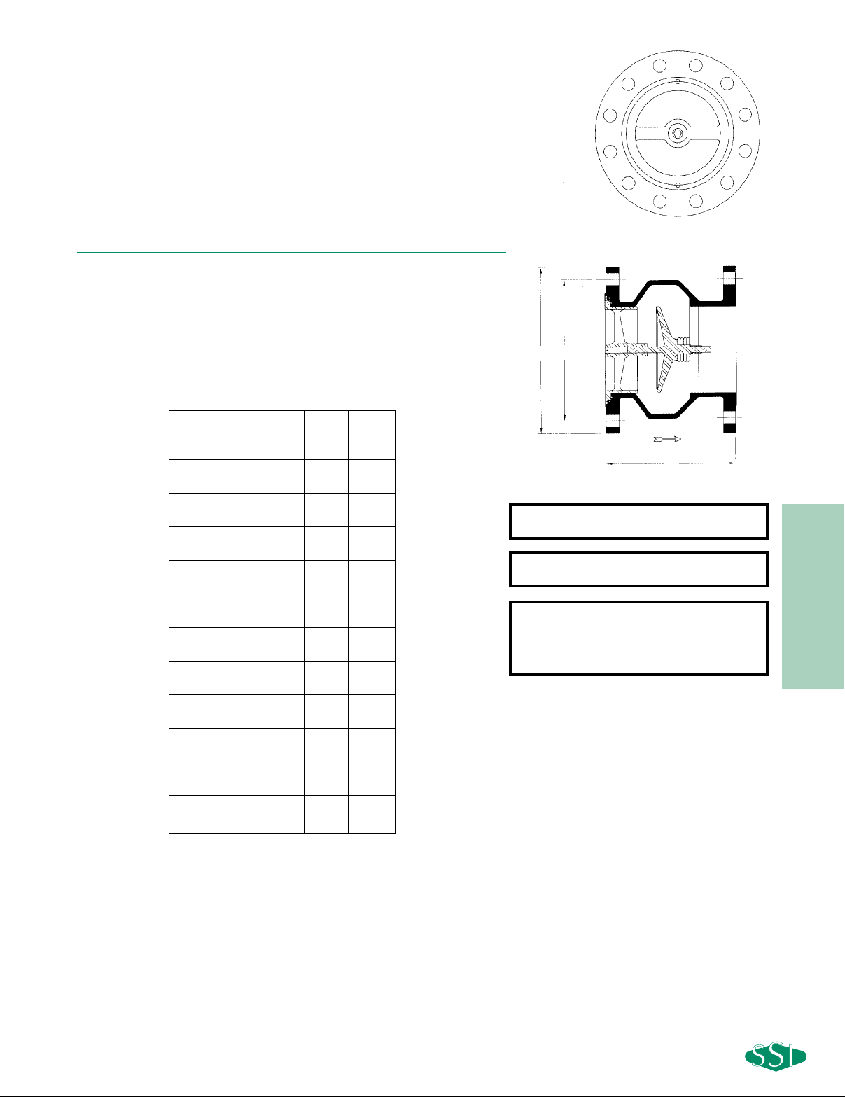
DIMENSIONS inches (mm) AND WEIGHTS pounds (kg)
Dimensions shown are subject to change.
Contact factory for certified prints when required.
Seats: 2" to 18" Bronze
Cracking Pressure:
Horizontal Mounting - .3 psid
Vertical Mounting - .75 to 1.25 psid
Size A B C Weight
26
1
⁄8 6 43⁄4 21
(50) (156) (152) (121) (9.4)
21⁄2 7 7 51⁄2 31
(65) (178) (178) (140) (13.8)
37
1
⁄2 71⁄2 6 37
(80) (191) (191) (153) (16.5)
48
1
⁄2 9 71⁄2 62
(100) (216) (229) (191) (28)
59
1
⁄2 10 81⁄2 80
(125) (241) (254) (216) (36)
6101⁄2 11 91⁄2 106
(150) (267) (280) (241) (48)
8131⁄2 131⁄2 113⁄4 175
(200) (343) (343) (299) (79)
10 161⁄4 16 141⁄4 267
(250) (413) (406) (362) (121)
12 201⁄4 19 17 477
(300) (515) (483) (431) (216)
14 223⁄4 21 183⁄4 785
(350) (580) (533) (477) (356)
16 243⁄4 231⁄2 211⁄4 900
(400) (629) (597) (540) (408)
18 221⁄2 25 223⁄4 1032
(450) (572) (635) (578) (468)
B
A
FLOW
C
FRONT VIEW
Page 3
FLANGED SILENT
CHECK VALVES
- 212 -
125FC SERIES
CAST IRON FLANGED SILENT CHECK VALVES
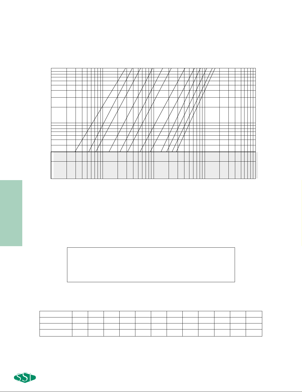
PRESSURE DROP VS FLOW RATE
(Sizes 2" - 18")
10
Installation Note:
1. For correct installation and maintenance please see our I&M manual.
2. Vertical installation (downward flow) – Consult factory.
3. Always use Strainers in upstream piping.
4. Not recommended for Steam Service
HORIZONTAL MOUNTED
Size (inches)
22
1
⁄2 3 4 5 6 8 1012141618
Min Cv (@.3 PSID)
53 99 135 246 402 566 1004 1579 2556 3286 4199 5112
CV (@1 PSID)
63 105 148 265 430 605 1105 1700 2575 3350 4300 5225
Max Cv (@10 PSID)
89 120 174 300 474 696 1297 1992 2593 3479 4427 5376
Cv Values
(1) Pressure drop curves are based on water flow.
(2) Valve cracking pressure is equal to or less than 0.3 psid when mounted horizontally.
(3) Valve cracking pressure increases to between 0.75 and 1.25 psid when installed
vertically with flow upwards.
FLOW RATE (GPM)
1
PRESSURE DROP (psi)
VALVE CRACKING PRESSURE
0.1
10 100 1000 10000 100000
4
2
3
2-1/2
5
FLOW RATE (GPM)
8
6
10
12
14
16
18
 Loading...