

Page 1
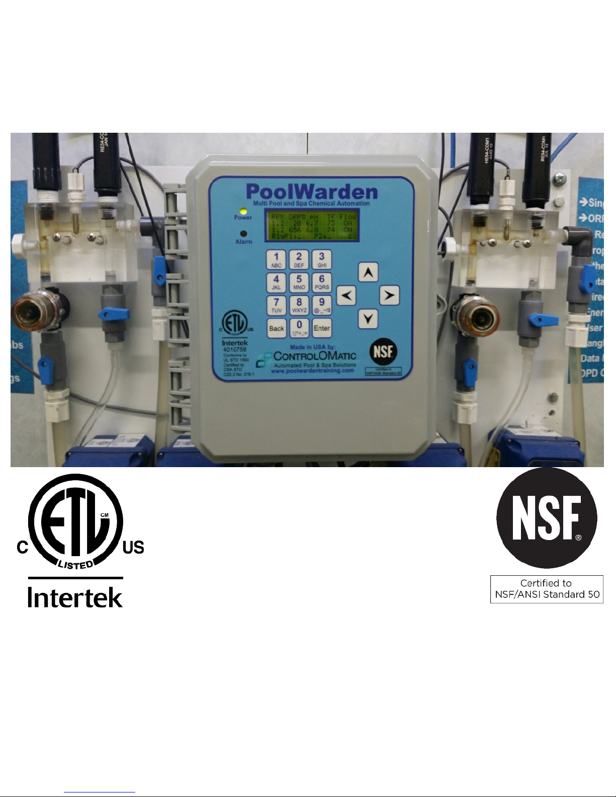
POOLWARDEN
Automated Pool & Spa Chemical Controller
And Data Recorder
Version: 110/220 VAC Web Server
12659 Arbor Lane, Grass Valley, CA 95949
Telephone (530) 205-4520 • www.controlomatic.com • www.poolwardentraining.com
Manual date 08/26/2016 Picture: PoolWarden DMTD
Installation
&
Operation
ControlOMatic, Inc.
Page 2

Contents
IMPORTANT WARNING AND SAFETY INSTRUCTIONS 3
POOLWARDEN OVERVIEW 5
SYSTEM COMPONENTS 5
Maximum Electrical Specifications 6
Certifications 6
Models and Options 6
POOLWARDEN INSTALLATION 7
Mounting PoolWarden 7
Flow Cell To Circulation Plumbing 7
Sensor Wire Connection 10
Supply 110/220 Vac Input Selection 10
Load / Equipment Connection & Installation 11
PoolWarden OPERATION 13
Default Readings Screen 14
MAIN MENU - SETUP 15
Information Menus 16
PROGRAMMING - GETTING STARTED 18
Step 1 - System Menu 18
Step 2 - Security Setup Menu 18
Step 3 - Relay Control Type Menu 19
Step 4 - Relay Setup Menu (ORP, pH and Alarms) 19
Step 5 - Service Menu 25
COMMUNICATION - GETTING STARTED: LAN / ETHERNET 26
Step 1 - The Communication Module 26
Step 2 - Network Setup Menu 26
Step 3 - Client IP Security 26
Step 4 - DATA SERVER SETUP 27
Step 5 - INFORMATION 27
Step 6 - EMAIL 27
COMMUNICATION: REMOTE CONNECTION 27
ADVANCED FEATURES 28
Data Recording Menu 29
Serial Printer 29
System Menu 30
Advanced Menu (Energy & CYA Management) 31
CHANGING RELAY TYPE 33
Heater Control Type 33
Feed Daily Control Type 34
Alarm Out Control Type 35
Superchlorination 35
Water Level Control Type 35
ORP Control Types 36
Replacement Parts 37
Maintenance 38
Troubleshooting 39
Technical Support 40
Change List 40
LIMITED WARRANTY 41
PoolWarden Manual www.poolwardentraining.com 530-205-4520 2
Page 3

IMPORTANT WARNING AND SAFETY INSTRUCTIONS
1 READ AND FOLLOW ALL INSTRUCTIONS
2 SAVE THESE INSTRUCTIONS
3 WARNING – To reduce the risk of injury, do not permit children to use
this product
4 DANGER – Risk of injury
4.1 Replace damaged cord immediately.
4.2 Do not bury cord.
4.3 Connect to a grounded, grounding type receptacle only.
4.4 Do not use an extension cord.
5 WARNING – This product is provided with a ground-fault circuit-
interrupter at the end of the power cord. The GFCI must be tested before
each use. Turn the PoolWarden off by placing the ON/OFF switch to the
OFF position. Next, push the test button on the GFCI and place the
ON/OFF switch to the ON position. The PoolWarden should not operate.
Now push the reset button on the GFCI and the PoolWarden should now
operate normally. When the product fails to operate in this manner,
there is a ground current flowing indicating the possibility of an electric
shock. Disconnect the power until the fault has been identified and
corrected.
6 It is very important to follow the safety guidelines in this manual to
ensure safe installation and programming. Upon installation, it is
important to properly train all personnel basic water quality
management techniques, proper operation and programming to anyone
who operates or services PoolWarden.
7 All applicable local installation codes and ordinances must also be
adhered to. Improper installation will create an electrical hazard which
could result in death or serious injury to pool users, installers or others
due to electrical shock, and may also cause damage to property. The
PoolWarden must be installed by a licensed or certified electrician or a
qualified pool professional:
7.1 United States: National Electrical Code (NEC), NFPA 70
7.2 Canada: Canadian Electrical Code (CEC), CSA C22.1.
8 WARNING – Disconnect all power to PoolWarden prior to any service
including the main AC power and any other AC sources that may be
connected to the AUX relays. Never apply power when PoolWarden
PoolWarden Manual www.poolwardentraining.com 530-205-4520 3
Page 4

service door is unlocked or in the open position. Only qualified and
licensed technicians should perform any service or repair.
9 WARNING – Always mount PoolWarden in safe and dry area. Never
mount PoolWarden above any other electrical equipment.
10 WARNING – Install PoolWarden in a location that is not accessible to the
public.
11 WARNING – Pool and Spa Chemical Safety
11.1 Never mix sodium hypochlorite and muratic acid!
11.2 When mixing acid and water, always add acid to the water, never
add water to the acid.
12 CAUTION – TEST THE GROUND FAULT CIRCUIT INTERRUPTER
BEFORE EACH USE OF THE POOL/SPA
13 CAUTION – CONNECT ONLY TO A CIRCUIT PROTECTED BY A CLASS A
GROUND FAULT CIRCUIT INTERRUPTER
1 ATTENTION: TOUJOURS VÉRIFIER L’EFFICACITÉ DU DISJONCTEUR
DIFFÉRENTIEL AVANT D’UTILISER LE BAIN
2 ATTENTION: LIRE LA NOTICE TECHNIQUE
3 AVERTISSEMENT: DÉCONNECTER DU CIRCUIT D’ALIMENTATION
ÉLECTRIQUE AVANT L’ENTRETIEN
4 ATTENTION: CONNECTER UNIQUEMENT À UN CIRCUIT PROTÉGÉ PAR
UN DISJONCTEUR DIFFÉRENTIEL DE CLASSE A
PoolWarden Manual www.poolwardentraining.com 530-205-4520 4
Page 5

POOLWARDEN OVERVIEW
ControlOMatic, with over 20 years of technological leadership in Pool & Spa Chemical Control Systems,
congratulates you on your selection of the PoolWarden Chemical Controller. PoolWarden measures pH,
sanitizer and temperature on up to two bodies of water and will control the appropriate feed equipment to keep
the measurements within a preprogrammed range. Using ORP (oxidation reduction potential) technology the
control of sanitizer takes into account the effects of pH, and a pH lockout feature is also included for high pH
values. Supporting both 110 and 220 VAC, the PoolWarden will control chemical feed equipment using relays
to keep the pool or spa water in balance. Water measurements are taken continuously while PoolWarden's
internal relay programing determines if chemical adjustments are needed. PoolWarden then communicates
the adjustment signals through relays which control the chemical feed equipment. PoolWarden also contains
additional dry-contact auxiliary relays that can be used to control heaters, pumps, chlorine backup and
external alarm notifications.
SYSTEM COMPONENTS
⧫ CONTROLLER: PoolWarden is a microprocessor based, modular automation system that is
capable of continuous monitoring locally onsite or remotely offsite.
⧫ INTERFACE: PoolWarden uses a 16-button built in keypad, and an easy to read 80 character
liquid crystal display. The display’s internal back-light provides controller viewing in pool rooms with low
light conditions. Back-light illumination time can be adjusted to suit the operator.
⧫ MEMORY: PoolWarden is designed with nonvolatile memory which preserves all internal programming in
case of power loss. Internal memory is preserved for up to 10 years without having power applied.
⧫ RELAYS: PoolWarden S (single pool) includes 4 relays (2 of which are dry contact relays). PoolWarden
D (two pools) includes 8 relays. Four of the 8 relays are dry contact relays (2 for each body of water).
⧫ SENSORS: ORP Sensor, pH Sensor, Temperature Sensor and Flow Sensor.
⧫ VOLTAGE: PoolWarden is designed with an ON/OFF switch and requires 120 VAC Input Voltage to
operate.
⧫ SECURITY: PoolWarden is designed with a lockable enclosure and provides up to four levels of password
security protection (Admin, Tech, Service and Guest) for both local onsite and remote offsite interaction
with the controller.
⧫ COMMUNICATION: PoolWarden can connect to the Internet for direct monitoring, setup, and data
interface via a WIFI or Ethernet option.
⧫ DATA: PoolWarden will record up to 8192 lines of data with the built in internal memory.
⧫ HEATERS: Auxiliary relays can control pool heaters with up to two set-points for each day to facilitate
energy management.
⧫ PUMP CONTROL: Auxiliary relays can be setup as a simple timer for controlling the on/off state of
main pumps.
⧫ OVERFEED PROTECTION: PoolWarden is designed with overfeed protection. Standard Overfeed limits
the amount of time a relay can turn on feed equipment in a 24-Hour period.
⧫ PROPORTIONAL FEED: Proportionally reduces the on-time as the measurement gets closer to the set-
point to prevent overshoot.
⧫ E-MAIL ALERTS: PoolWarden provides support for 4 email addresses. Alarm alerts can be sent directly
from the controller for real-time management.
⧫ DIGITAL FLOW SENSORS: PoolWarden can track flow rate and flow volume.
⧫ AUXILIARY RELAYS: Auxiliary relays can control additional / backup sanitizer or acid feed pumps.
PoolWarden Manual www.poolwardentraining.com 530-205-4520 5
Page 6

Maximum Electrical Specifications
ITEM DESCRIPTION LIMIT
Input Voltage Maximum input AC voltage 220 VAC, 50-60 Hz
Input Current Maximum input current 10 A
Relay Voltage Maximum relay voltage 220 VAC
Relay Current Maximum Relay Current 2.5 A
Temperature Minimum/Maximum Operating Temperature 30/110 °F
Standby Current Maximum operating current 0.1 A Max
pH Measurement of pH 4.22 to 9.98
ORP Oxidation Reduction Potential 0 to 999 mV
Temperature Water temperature measurement. 32 to 122 °F
Models and Options
ITEM DESCRIPTION
PW-XFC PoolWarden controller with flow cell and sensors
PW-XFC-P
PW-XFC-PE Add 2 pigtails per pool and Ethernet communication
PW-XFC-E Add Ethernet communication
PW-XMTD
PW-XMTD-P Add 2 pigtails per pool for easy connection of external feeders
PW-XMTD-PE Add 2 pigtails per pool and Ethernet communication
PW-XMTD-E Add Ethernet communication
TrueDPD
X In the above model numbers, replace the x for S (Single pool) or D (Dual Pool)
Add 2 pigtails per pool for easy connection of external feeders
PoolWarden controller with flow cell and sensors pre mounted on white back panel
Adds free chlorine measurement using the DPD colorimetric method. This is available
as a single and dual sensor.
Certifications
4010758
Conforms to
UL STD 1563
Certified to CSA STD
C22.2 No. 218.1
PoolWarden Manual www.poolwardentraining.com 530-205-4520 6
NSF/ANSI 50 - Equipment for
Swimming Pools, Spas, Hot
Tubs and Other Recreational
Water Facilities
http://info.nsf.org/Certified/Pools/Listin
gs.asp?Company=C0214550&Standar
d=050&
Page 7

POOLWARDEN INSTALLATION
Mounting PoolWarden
Turn off any heaters, pool or spa circulation systems, chemical feed pumps or any related shut-off valves or
equipment and relieve pressure from the filtration system. Find a suitable mounting location near a 120/220
VAC power source that meets the following criteria:
⧫ Facilitates a combined (influent & effluent) maximum tubing run of 30’.
⧫ Do not mount controller above electrical sources or electrical equipment.
⧫ At least 10’ away from any pool, spa or body of water and not accessible to the public.
⧫ Away from corrosive materials and physical hazards.
⧫ Not in direct sunlight or directly above or near any heat source.
⧫ For 220 VAC, ability to hard wire with GFCI (ground fault circuit interrupter) protection.
Securely mount controller, or the optional controller backboard, vertically on the wall using supplied screws or
appropriate fasteners for the wall construction. Never mount MiniWarden horizontally.
Flow Cell To Circulation Plumbing
There are many ways to connect the flow cell tubing to the circulation plumbing. Always make sure the input
source to the flow cell is well upstream from any chemical injection points. Successful flow cell installation
requires a pressure differential, or there will be no water flowing through the cell. The Flow cell input should be
filtered water and therefore after the filter. Never install the input to the flow cell between the main circulation
pump and filter as that will be very high pressure which may damage the pump and provide the most debris to
the flow cell. PoolWarden is equipped with a strainer to filter out any debris that does get past the filter.
Periodically check and clean the strainer. Install the flow cell return after the heater, there will be a pressure
drop across that should be sufficient to provide flow through the flow cell. If there is no heater, the next choice
is the suction plug in the pumps strainer, make sure to adjust the return valve on the flow cell to keep the
pressure in the flow cell positive.
⧫ Flow Cell Input: Drill & tap a connection point in the circulation system at a location just after the filter. The
best location is where there is a pipe fitting as that will provide the most threads. Install a tube connector
and run tubing to the input side of the flow cell.
⧫ Flow Cell Output: Drill & tap a connection point in the circulation system at a location with reduced
pressure just after the heater. Install a tube connector and run tubing to the return side of the flow cell.
CAUTION: Maximum pressure across the sensors should be 10 PSI (pressure gauge may be required).
Always expose the sensors to positive pressure. Prevent exposing the sensors to suction or a vacuum by
connecting the flow cell output tubing to the suction side of the pump as the vacuum may suck the sensor gel
from the sensors rendering the sensors inoperable in a very short period of time.
⧫ If not pre-mounted, find a suitable location to mount the acrylic flow cell within 3 feet of the controller.
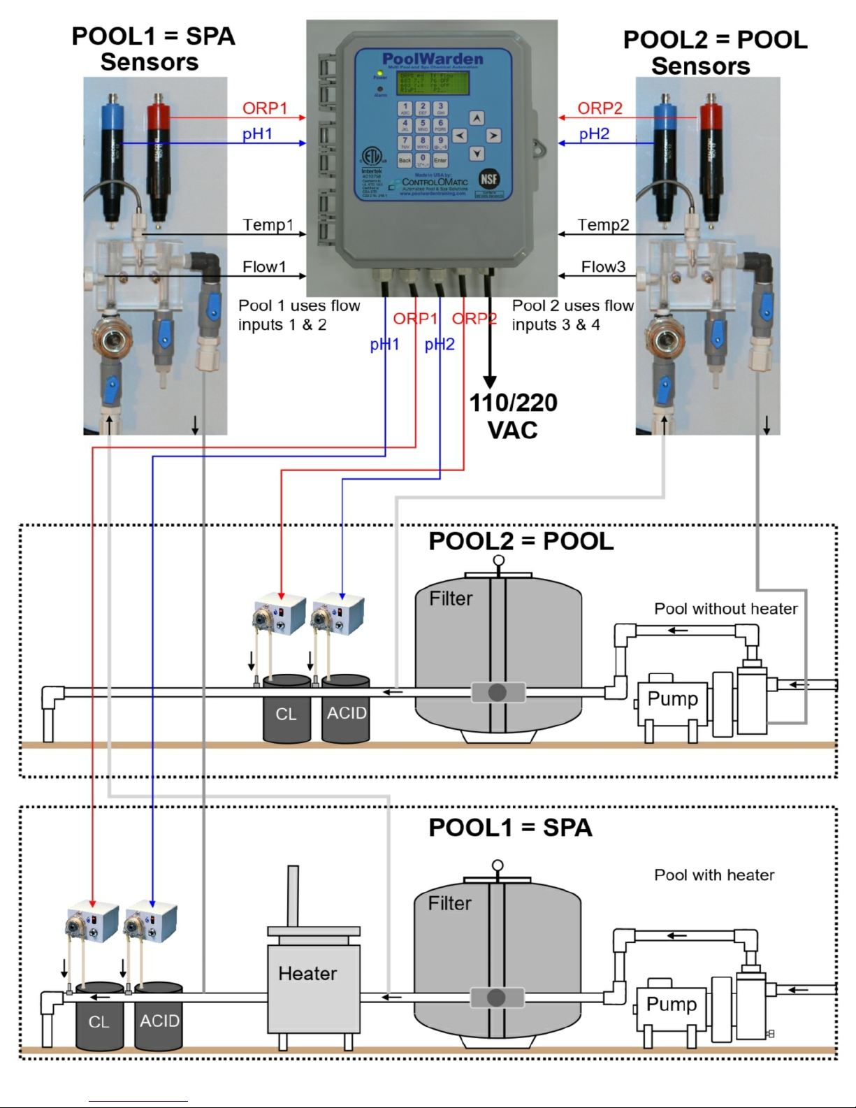
Mount and assemble flow cell parts according to Picture 2.
⧫ Remove pH (Blue) and ORP (Red) sensors from the boxes. Use Teflon tape on sensor threads and all
other flow cell parts to ensure water tight connection and fasten accordingly.
⧫ Install the appropriate 1/2” or 3/8” hard vinyl input and output tubing from the pools circulation system
connection points to the “In” and “Out” connection points on the flow cell according to Picture 2.
⧫ Once connected, turn circulating pump back on, test for leaks at all connection points, and make sure all air
evacuates form the tubing.
⧫ There is a small magnet in the flow cell that is held in place with a piece of tape. Remove the tape and
make sure the magnet remains in the hole above the filter / strainer.
PoolWarden Manual www.poolwardentraining.com 530-205-4520 7
Page 8
PoolWarden Manual www.poolwardentraining.com 530-205-4520 8
Page 9
PoolWarden Manual www.poolwardentraining.com 530-205-4520 9
Page 10
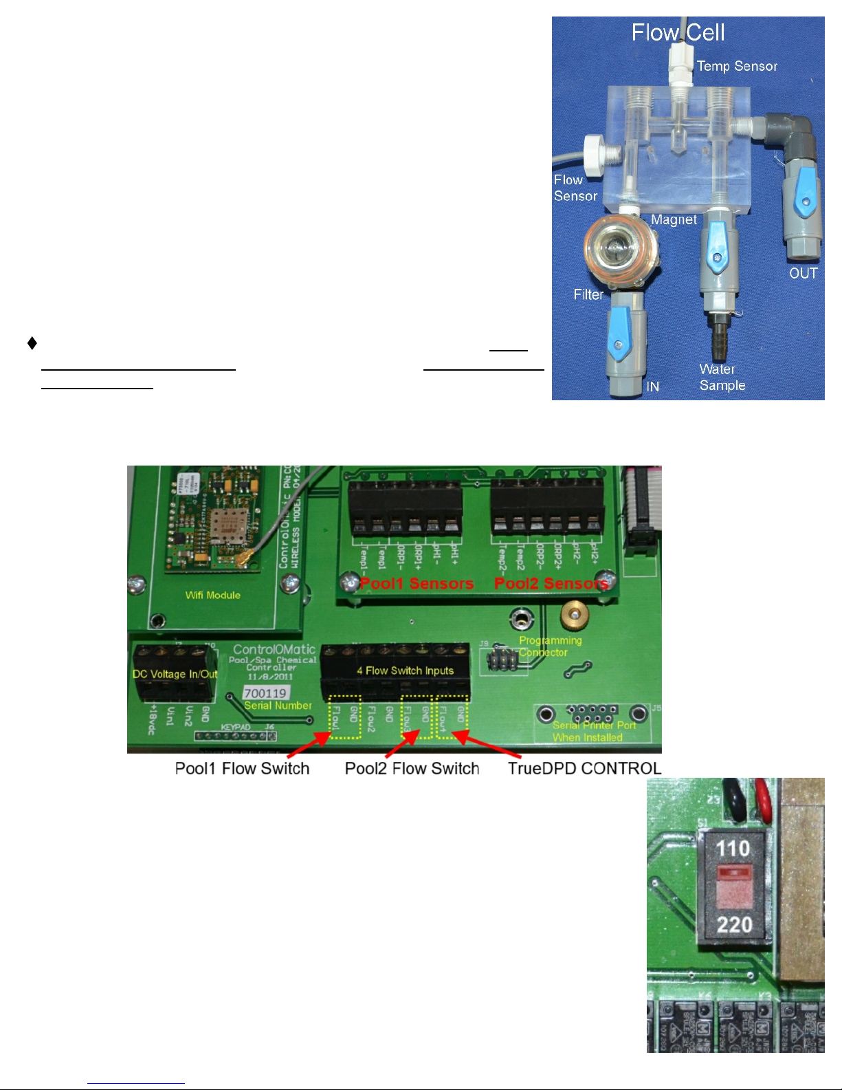
IMPORTANT NOTE: There needs to be just enough flow (0.5 gpm)
through the flow cell to raise the flow magnet inside the flow cell to
make contact with the flow sensor. To test this, turn the “input” shut-off
valve to the off position and watch the flow magnet drop from the flow
sensor. Next, turn the input shut-off valve back on and watch the flow
magnet rise to the flow sensor. If the flow magnet rises abruptly and
pings/knocks the flow cell acrylic then the flow is too high. To reduce
flow, perform the same exercise, but now open the shut-off valve slowly
and stop when you see the magnet “slowly” rise to make connection
with the flow sensor. Leave the shut-off valve in that position.
PICTURE 2
Sensor Wire Connection
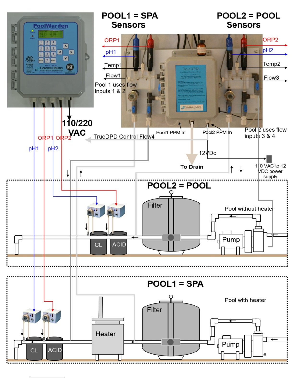
If not pre-mounted, route the pH (Blue Sensor Wires), ORP (Red
Sensor Wires), flow sensor and temp sensor wires through the cable
grips at the bottom of controller and connect as labeled inside or as
indicated below in PICTURE 3. Note: Black wires are always
negative (-) and the Clear or Red wires are always positive (+).
REQUIRED Flow Sensor Connections: Connect flow sensor wires
for pool #1 to flow switch 1 and connect flow sensor wires for pool #2
to flow switch 3.
⧫ Optional Flow Sensor Connections: Flow switch 2 & 4 are auxiliary switches for Pool #1 and Pool #2
respectively. For powered 3 wire digital flow meters or water level indicators use the 18VDC connection on
the left of the main board, note that it has a 1 amp fuse.
Supply 110/220 Vac Input Selection
The PoolWarden supports both 110 VAC and 220 VAC. For 110 VAC the power
cord includes a GFCI on the end of the cord that plugs in. For 220 VAC the cord
should be removed and the PoolWarden should be hardwired to a circuit breaker
with a GFCI by a licensed electrician. The cord can be returned to ControlOMatic for
a credit.
⧫ VAC Selector: The red switch in the center of the bottom circuit board must have
the switch notch up for 110 VAC, and down for 220 VAC. Incorrect selection will
damage the PoolWarden.
⧫ A good solid earth ground is required for PoolWarden to work properly. Without
a solid ground connection the sensors may drift.
PoolWarden Manual www.poolwardentraining.com 530-205-4520 10
Page 11
⧫ The ORP and pH relay are directly connected to the input VAC. If you have the PoolWarden set for 220
VAC then the loads must also be 220 VAC.
For 220 VAC operation, the neutral line will be connected to the Red 220 VAC wire and the Line
connection will be to the Black 220 VAC wire. The Neutral connection for pH and ORP relays switches the
Neutral input VAC wire. The relays are double pole double throw and break both lines.
Load / Equipment Connection & Installation
ORP & pH RELAYS: The chemical feed relays for pH and ORP are internally connected to the input VAC
main input which is located on the right side connector on the circuit board through 10 AMP fuses F1 and F2.
No voltage is being supplied to the load / equipment when the relay is off, hence, voltage is being supplied to
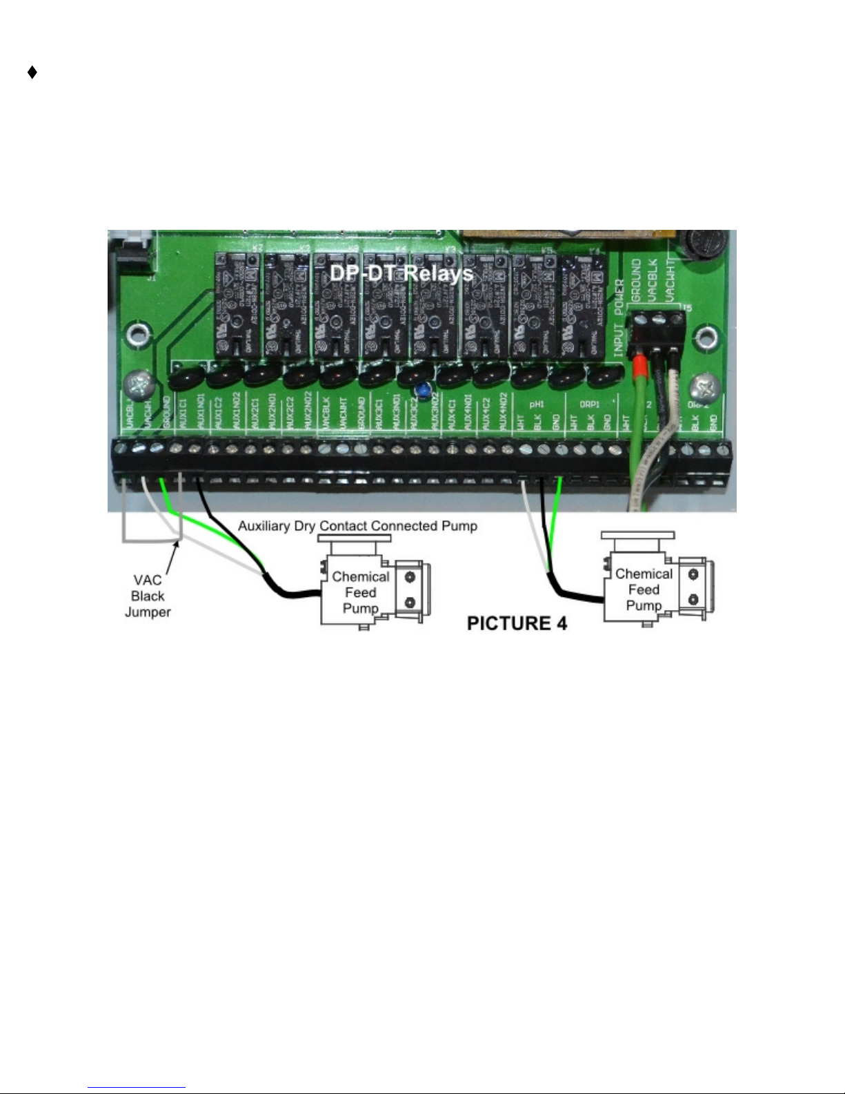
the load / equipment when the relay is on. Any standard chemical feed pump or solenoid can be hard wired
directly into the appropriate ORP and pH connection terminals as shown below in PICTURE 4 so long as their
voltage matches the input VAC connected to the PoolWarden.
⧫ VACBLK: Connection to the VAC black (Line) wire
⧫ VACWHT: For 110 VAC connect to the input white neutral wire. For 220 VAC connect to the red VAC wire.
⧫ PH / ORP WHT: For 110 connect to the white neutral wire on the load. For 220 connect to one of the Line
connections.
⧫ PH / ORP BLK: For 110 connect to the black line wire on the load. For 220 connect to the other Line
connection.
⧫ PH / ORP GND: Connect to the green ground wire on the load.
DRY CONTACT RELAYS: A dry contact relay is not connected to any voltage and acts as a switch. To
supply power to a load / equipment (such as a chemical pump) through any of the auxiliary dry contact relays,
the voltage must be supplied using a jumper to the main input voltage. To facilitate this jump, PoolWarden is
equipped with terminals right next to the auxiliary dry contact relay terminals labeled VACBLK, VACWHT and
GROUND. Please note that these VAC terminals are after the 10 AMP fuses F1 and F2.
Relay Board Acronyms for the Auxiliary Dry Contact Relays:
⧫ AUX#NO1: Normally Open aux relay, side 1 of the relay
⧫ AUX#NO2: Normally Open aux relay, side 2 of the relay
PoolWarden Manual www.poolwardentraining.com 530-205-4520 11
Page 12
⧫ AUX#C1: Common connection to relay # side 1.
⧫ AUX#C2: Common connection to relay # side 2.
⧫ GROUND: Connected to the GROUND connection on the input VAC terminal.
⧫ VACBLK: A convenient connection to the input VAC black line wire.
⧫ VACWHT: A convenient connection to the input VAC white neutral wire.
⧫ GROUND: A convenient connection to the green ground wire.
Supported Auxiliary Dry Contact Loads / Equipment:
⧫ Standard Chemical Feed Pumps: Any Chemical Feed Pump can be connected to an Auxiliary Dry Contact
Relay as shown in PICTURE 4 on the previous page. This may be needed to set up a back up sanitizer to
the main sanitation control. A black wire 110 VAC jumper is needed to energize the dry contact for 110
VAC operation and two jumpers for 220 VAC operation..
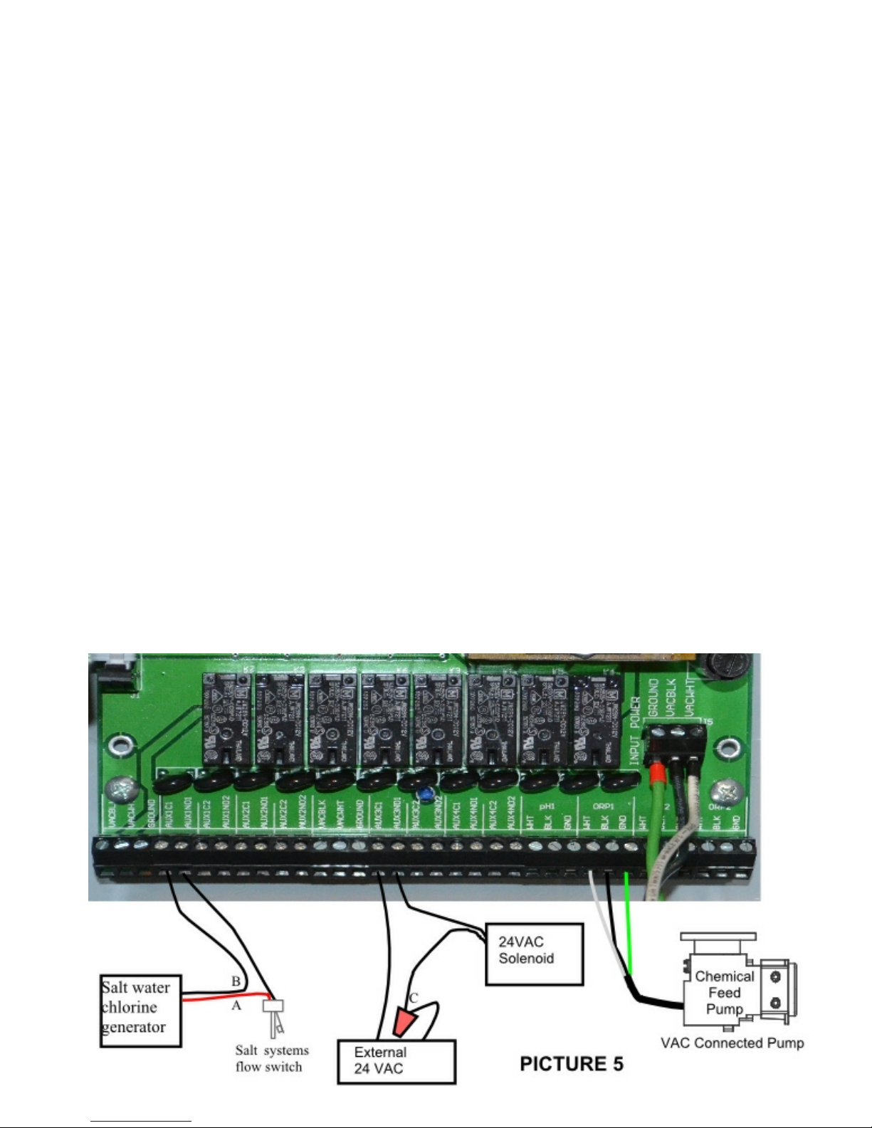
⧫ Chlorine Generators: A high power chlorine generator should not be powered using PoolWarden’s internal
power as it may exceed the input 2.5 AMP relay rating. Simply connect an auxiliary dry contact to control
the on/off status of the generator. When PoolWarden’s relay turns on, while the flow switch is on, then the
chlorine generator will turn on. When the relay is turned off it makes the chlorine generator think there is
no flow, and the chlorine generator will turn off.
⧫ Loads / Equipment Using External 24 VAC (Erosion Feeders & Suction Side Cal Hypo): Solenoids are
used to control water flow through a chlorine erosion feeders and suction side cal hypo systems and most
use 24 VAC. Install a 24 VAC Transformer external to the PoolWarden and connect one of the output
leads to an AUX#C1 relay and connect the AUX DRY#NO1 to the solenoid as shown in PICTURE 5.
Connect the other 24 VAC Transformer wire to the remaining solenoid wire (C). If the 24 VAC Transformer
has a an output ground wire then connect it to one of the Ground terminals on the relay board.
⧫ Circulation Pumps: Never connect a circulation pump directly to any of the relays inside PoolWarden.
Always use an external High-Power Relay that the Auxiliary Dry Contact Relay inside PoolWarden can
control. Please refer to the circulation pump’s manual for proper set-up and control of a variable speed
pump.
⧫ External Alarms (Light or Sound): If a more noticeable alarm notification is needed beyond the red LED on
PoolWarden’s front panel, a relay can be set up to output the alarm status to an external buzzer or light.
PoolWarden Manual www.poolwardentraining.com 530-205-4520 12
Page 13
PoolWarden OPERATION
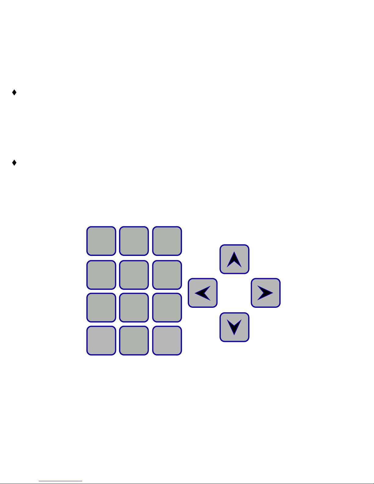
This section reviews all the navigation features associated with PoolWarden’s keyboard.
⧫ Back: From the main readings display the Back button provides access to the main menu where all of the
configurations are. If PoolWarden is password protected then you will need to enter the password to
access the main menu. The Back button will also go back one menu from almost any screen and pressing
it enough times will get back to the readings display.
⧫ Enter: The Enter button provides access to most menus and sub menus within PoolWarden and allows
you to accept or save an entry.
Number & Text Keys: The number and text keys allow you to change numerical values and text in many
menus.
❑Number Keys: “0 through 9” change numerical values.
❑Text Keys: Some menus allow for entering or changing text. The first press of a number key will display
the number. The next press will display the first Lower-Case letter below the number and so on.
Continuing to press the key will display Upper-Case letters.
❑When the cursor is in the first position, pressing the left arrow key will toggle between upper and lower
case.
Arrow Keys: The arrow buttons (Up, Down, Left & Right), allow navigation within each menu. All menus
are fully rotational which means if you use the Up arrow to scroll to the top of a menu and press it one
more time - you will be at the bottom of that same menu and vise-versa.
❑Up Arrow: Moves the cursor up one selection in a menu.
❑Down Arrow: Moves the cursor Down one selection in a menu. Also used to cancel changing a value.
❑Left Arrow: Moves back to the previous menu just like the Back button.
❑Right Arrow: Selects the item the cursor is currently on just like the Enter button.
1
1
ABC
4
JKL
7
TUV
Back
2
DEF
5
MNO
8
WXYZ
0
.’()*+,;=:
3
GHI
6
PQRS
9
@-_~!$
Enter
PoolWarden Manual www.poolwardentraining.com 530-205-4520 13
Page 14

Default Readings Screen
The Default Readings Screen is displayed after power up and when a button
isn’t pressed for a period of time. It is the most critical screen as it will
display the current pH & ORP sensor readings, flow status, relay status,
alarm status and various symbols that are defined below. Menus within
PoolWarden are accessed through the Default Readings Screen . Please
review definitions of all Row & Column information and symbols below.
Row 1 (Column Header): The first row is a column header and defines what you find below that particular
column header. Example above: The “pH” Column Header on the first row means that the current pH
readings for Pool 1 (7.7) and Pool 2 (7.5) are just below. When the PoolWarden is turned on a number will
display on this line to the right which is a delay before the relays will operate, the turn on delay gives time
for accurate reading prior to controlling the relays.
Row 2 (Current Measurements Pool1): The current real time measurements and status for Pool 1.
Example above for Pool 1: ORP=681, pH=7.7, Temperature (Tf) = 75 degrees Fahrenheit, Flow = ON. The
“a” on the far right indicates that Pool1 is in alarm.
Row 3 (Current Measurements Pool2): The current real time measurements and status for Pool 2.
Example above for Pool 1: ORP=695, pH=7.5, Temperature (Tf) = 102 degrees Fahrenheit, Flow = ON
and the alarm is not on for Pool2.
Row 4 (Relay Status): Row 4 displays the current status of all the relays in the following order with
symbols that are defined below (RlyP1 = Pool1 and P2 = Pool 2);
m
v
Default Readings Screen
ORP pH Tf Flow
681 7.7 75 ON a
695 7.5 102 ON
RlyP1↑↓o_ P2_↓o_ N
❑RlyP1: ORP1, pH1, Aux1, Aux2 P2: ORP2, pH2, Aux3, Aux4
❑_ : An underline indicates the relay is OFF and not in an active feed cycle.
❑↑ : An Up arrow indicates the relay is ON and in an active feed cycle.
❑↓ : A Down arrow indicates the relay is OFF and in the OFF part of an active cycle.
❑o : An "o" indicates the relay has reached the on time limit (overfeed limit) for the day and will not turn
on again until the overfeed limit clears automatically each night at midnight or when PoolWarden’s
power is cycled.
s : An "s" indicates the relay has reached the setpoint overfeed limit and will not turn on again until
the setpoint is achieved by other means (manually adding the required chemicals). The only other way
to clear this is to cycle power. NOTE: The setpoint overfeed will not clear when the Clear Overfeed
menu item is selected in the service menu or at midnight like the daily overfeed.
❑The letter ‘b’ next to an ORP reading indicates ORP is in pH lockout and ORP backup is on.
❑The letter ‘p’ next to an ORP reading indicates ORP is in pH lockout and is off.
Other Symbols Defined:
❑The letter “a” on the right will display when the Pool alarm is on.
❑“p” In the last 4 characters of the display screen, indicates a user PIN code has been entered, this will
clear when it is sent to the server.
❑“N” or “c” is displayed in the lower right indicates communication status with remote networks.
❑The LOCK symbol in the lower right indicates security is enabled.
Flow Status: The flow will either be ON or OFF with the standard flow sensor or if a digital flow sensor is
used. Digital flow sensor indication will be ON if the sensor is active. Flow status for Pool 1 uses Flow 1
input for the sensor connection and Pool 2 uses Flow 3 input for the sensor connection on the sensor
circuit board. This cannot be changed. For status with digital flow sensors press the Up Arrow to access
the digital flow sensor screen.
PoolWarden Manual www.poolwardentraining.com 530-205-4520 14
Page 15

MAIN MENU - SETUP
Simply press the Back button from the Default Readings Screen to gain access to the “Main Menu”. From the
“Main Menu” use the Up & Down arrow keys to navigate to each sub menu item and press Enter to go to that
sub menu or selection. Accessing the Main Menu can be password protected and the available selections will
be dependent on the security level of the password.
The menu selections will vary based on the following options: 1) Single/Dual pool version, 2) PW-Lan Ethernet
option, 3) TrueDPD enabled and 4) Serial printer added.
Main Menu
Service
Relay Manual
Calibration P1
Calibration P2
Disable Relays
Clear Overfeed
TrueDPD PPM Manual
DPD Level 55%
Data
Go To Data
Interval 01:00:00
Clear Data
Used: 808/8192
Serial Printer
Print Data
Print: Off
Print Last 7
Relays
PH1 Acid(pH-)
ORP1 Feeded(ORP+)
Aux1 Not Used
Aux2 Not Used
Alarm1 Standard
PH2 Acid(pH-)
ORP2 Liquid(ORP+)
Aux3 Not Used
Aux4 Not Used
Alarm2 Standard
Default Readings Screen
m
ORP pH Tf Flow
v
681 7.7 75 ON a
695 7.5 102 ON
RlyP1↑↓o_ P2_↓o_ c
Back
Press
Back Key
Main Menu
Service LAN
Data Security
Relays Relay Type
Advanced System
System
Time: 12:36:17
Date: 03/27/15
Day : Friday
Backlight Time 500
Name: PoolWarden
Units: English
Flow Menu
ORP Cal: Enabled
PoolWarden (Dual)
Daylight Savings No
Langelier pH +/-0.2
TrueDPD Menu
Service QuickJmp On
Display Type: VFD
Clear/Reset Menu
Overlay Color White
Scroll Readings OFF
LAN
Data Server Setup
Network Setup
Information
Email
Client IP Security
Security
0Admin
1Tech
2Tech
3-9Service
Clear All Passwords
Relay Type
Pool-1
Update Pool1
Pool-2
Update Pool2
PoolWarden Manual www.poolwardentraining.com 530-205-4520 15
Page 16

Information Menus
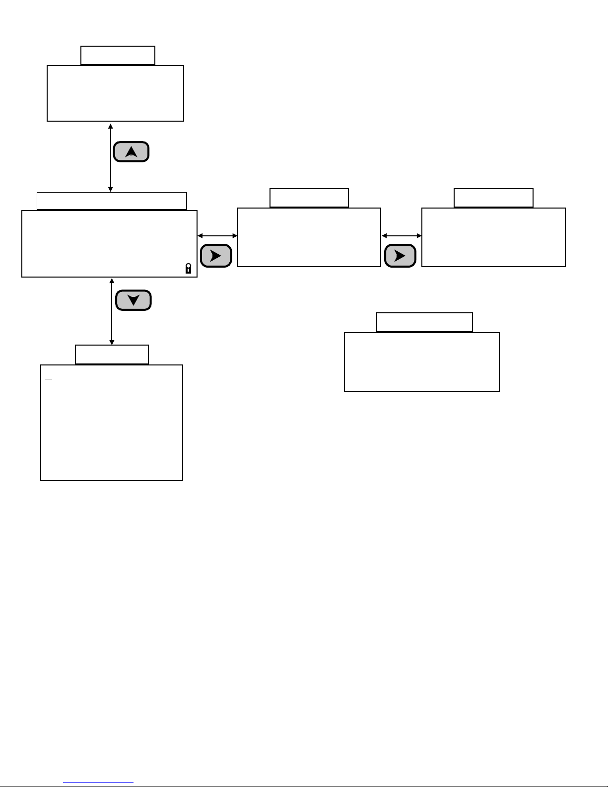
PoolWarden has 4 Menus (Main, Handy, Flow & Alarm) which are all accessible directly from the Default
Readings Screen. The Handy Menu, Flow Menu, and Alarm Menus are NOT password protected.
Handy Menu: Press ▼ Down Arrow or Enter from the default readings screen.
❑Enter Password: Allows for the entry of a password if PoolWarden has been security enabled.
Last 7 Days Data: Allows scrolling through the last 7 noontime readings to enter into the pool log.
❑Startup Screen: This will show the initial start up screen when PoolWarden is turned on. It will display
the serial number and software version.
❑Enter Service Pin: Service Technician can be assigned a Pin Code to enter into this section when a
pool is being serviced. This feature only applies when PoolWarden is Communication Enabled and can
send / store data at www.PoolWarden.com.
❑Enter Measurements: The following manually taken pool measurements: PPM, pH, ALK, Hard and
CYA can be entered here. If PoolWarden is communication enabled then the data will be sent / stored
at www.PoolWarden.com. Entering these manual measurements will also enable the Langelier Index
Adjustment in the System Menu. See Langelier pH in the System Menu for more information.
❑Last Month On Times: Will display the full amount of time each relay was ON for last month and
current month.
❑Relay Information: Displays relay type, Length of time on for day and month, Number of times relay
has been turned on for the day. Enter 0 to 4 for Pool1 relays, and 5 to 9 for Pool2 relays.
❑System Information: List the total hours the unit has been on, total number of power up cycles, total
number of times a PIN has been entered and the total number of times manual measurements.
Digital Flow Screen: Press the ▲ Up Arrow from the readings screen to access the flow screen which
shows all 4 flow switch inputs and the flow rates if any are setup as a digital flow sensor. If the TrueDPD is
connected, flow switch input number 4 is used for communication and control and isn’t available as a flow
input.
⧫ Alarm Screen: Press ► Right Arrow from the readings screen to access the alarm menu. The alarm
screen shows all alarms even if the current alarm is OFF. There are many conditions that can turn the
alarm light on. Those conditions are set up for each pool in the Relay Setup Menu. The alarm screen lists
the condition that have already turned the alarm on, or will turn the alarm on after the delay.
Langelier Index: If manually taken measurements have been entered in the Handy Menu, press the ►
Right Arrow from the Alarm Screen to access the Langelier index values. The measurement uses the
manually entered ALK, Hard and CYA and the current measurement for pH and temperature. The screen
displays the current Langelier index, and what it would be if the pH was at the setpoint (desired value).
Set Point Screen: Pressing the 9 key from the readings screen will show current set-points.
PoolWarden Manual www.poolwardentraining.com 530-205-4520 16
Page 17
Flow Info
Flow1 ON
Flow2 OFF 0.00 gpm
Flow3 OFF
Flow4 OFF
Press
Up Arrow
Information Menus
Default Readings Screen
m
ORP pH Tf Flow
v
681 7.7 75 ON a
695 7.5 102 ON
RlyP1↑↓o_ P2_↓o_ c
Press
Down Arrow
Handy Menu
Enter Password
Last 7 Days Data
Startup Screen
Enter Service Pin
Enter Measurements
Last Month On Times
Relay Information
System Information
Press
Right Arrow
Alarm Info
Pool1 Active Alarms
On If ORP < 650
On If Temp < 78.0
Pool2 Active Alarms
PoolWarden Dual
Pool/Spa Controller
03/04/16 09:34:31
SN: 700119 08/28/16
Line 3: Current date and time
Line 4: Serial number and software date.
Langelier Info
Langelier Sat index
1=-0.1/0.1 Balanced
2=0.6/0.3 Scale
Current/At Setpoint
Press
Right Arrow
Startup Screen
Quick Keys
2: If quick menus enabled, ORP setpoint and mixing times setup
3: If quick menus enabled, pH setpoint and mixing times setup
6: TrueDPD information screen, press 9 in this screen to start a measurement
9: Display the setpoints
PoolWarden Manual www.poolwardentraining.com 530-205-4520 17
Page 18
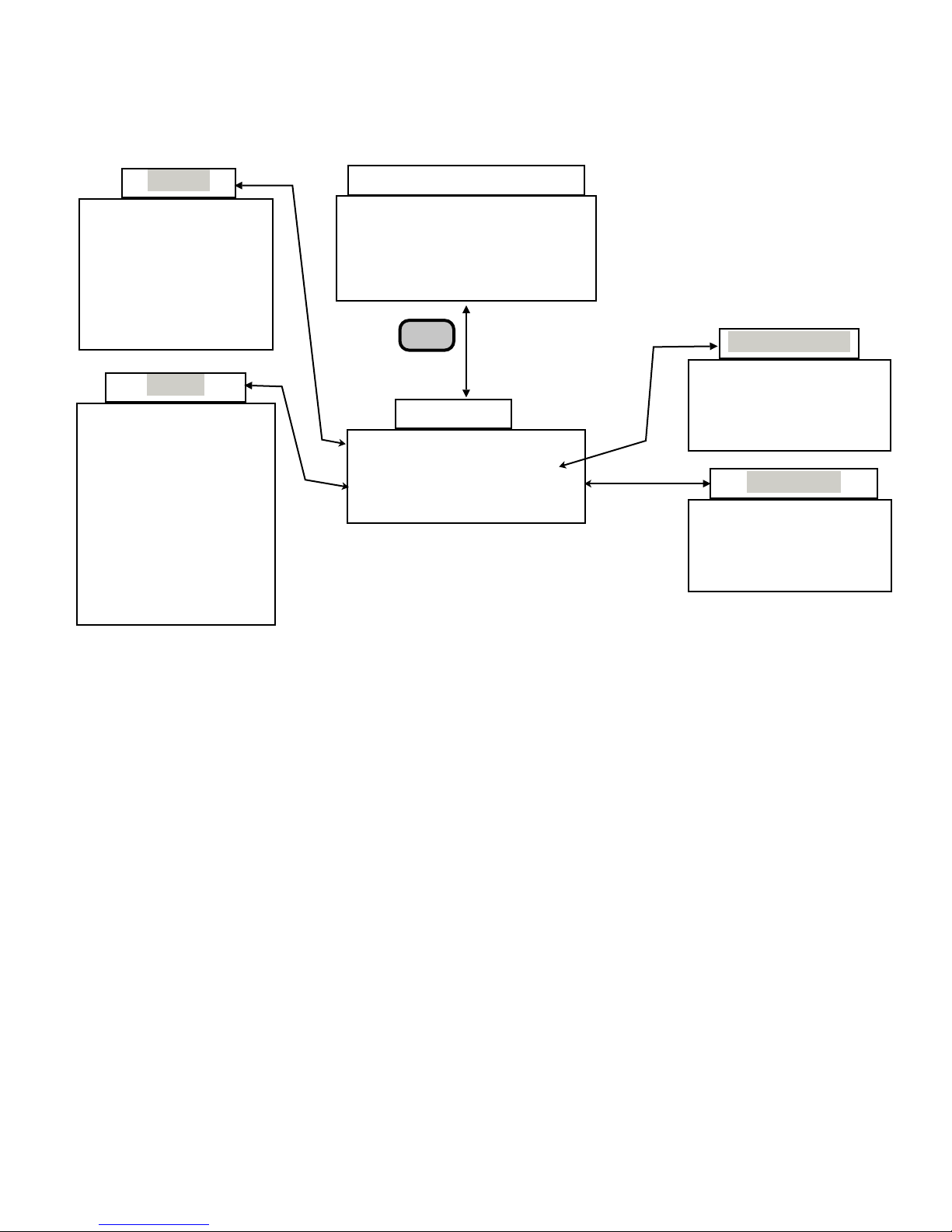
PROGRAMMING - GETTING STARTED
The menu tree below represents the “Getting Started” menus that are necessary to get PoolWarden setup.
The remaining menus represent more advanced features that will be covered in later sections. Become very
familiar with the 4 menus below surrounding the Main Menu as they will be utilized most of the time. Any
menu utilizing the Back button for access can be password protected.
Service
Relay Manual
Calibration P1
Calibration P2
Disable Relays
Clear Overfeed
TrueDPD PPM
Manual
Relays
PH1 Acid(pH-)
ORP1 Feeded(ORP+)
Aux1 Not Used
Aux2 Not Used
Alarm1 Standard
PH2 Acid(pH-)
ORP2 Liquid(ORP+)
Aux3 Not Used
Aux4 Not Used
Alarm2 Standard
Default Readings Screen
m
ORP pH Tf Flow
v
681 7.7 75 ON a
695 7.5 102 ON
RlyP1↑↓o_ P2_↓o_
Back
Press
Back Key
Main Menu
Service LAN
Data Security
Relays Relay Type
Advanced System
GETTING STARTED
PROGRAMMING
Security Setup
0 Admin
1 Tech
2 Tech
3-9 Service
Relay Type
Pool-1
Update Pool1
Pool-2
Update Pool2
Step 1 - System Menu
The first step is to set the Date, Time and Day of the Week in the System Menu. Press the Back button to
access the “Main Menu” and scroll down to the “System Menu” and set the correct Date, Time and Day of the
week and then proceed to Step 2 below. Much more will be covered on the “System Menu” in the Advanced
section of this manual.
Step 2 - Security Setup Menu
The next step is to set up and assign passwords to the various personnel who will be working with or servicing
PoolWarden. Menus that are accessed from the “Default Readings Screen” using the Back button can be
password protected. The Handy Menu, Flow Menu and Alarm Menu are not Password Protected - anyone
can access them. From the “Default Readings Screen”, simply press the Back button to access the “Main
Menu” and use the Down Arrow to scroll to “Security Setup”. There are 3 levels of access that are defined
below. Scroll to the level and assign up to a 10 digit password (numbers only) and press “Enter” to save the
password. Entering zero “0” will disable a password and the maximum value for any password is
4294967295.
● 1 Admin Password: Access to all menus within PoolWarden including ability to add, delete, or change
passwords. If the Admin Password has been lost, please read the troubleshooting section at the end of
this manual.
● 2 Technician Passwords: Access only to the Service Menu, Data Recording Menu, Relay Setup and
Advanced Menus.
● 7 Service Passwords: Access only to the Service and Data Recording Menus.
If direct communication is required with the optional PW-LAN, security must be enabled to allow access to the
Main Menu.
PoolWarden Manual www.poolwardentraining.com 530-205-4520 18
Page 19
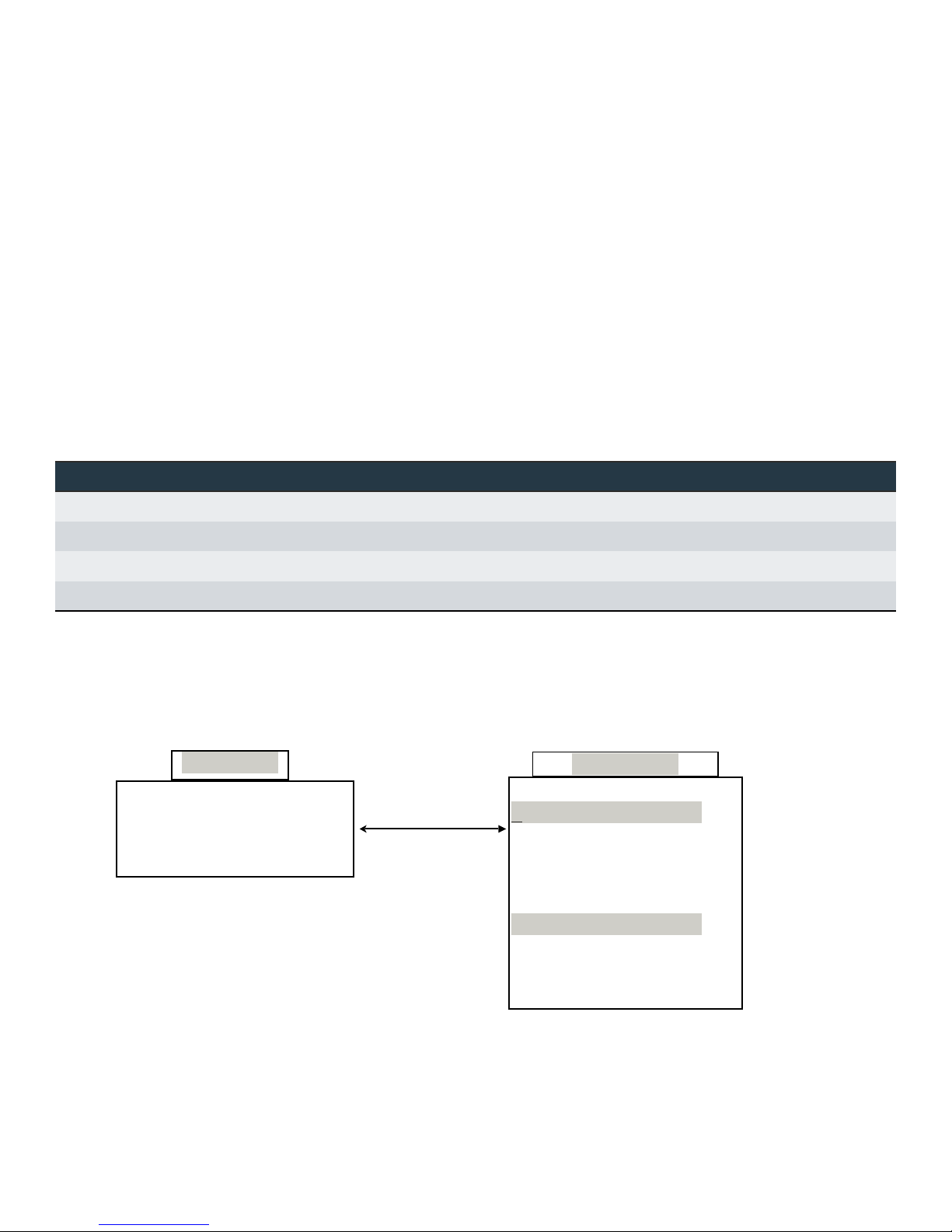
Step 3 - Relay Control Type Menu
The Relay Control Type Menu is the next step in programming PoolWarden and getting started. The Relay
Control Type Menu sets each relay to the control type the relay will use. For Example: Will the ORP Relay for
Pool 1 be using Liquid Chlorine, an Erosion Feeder or a Salt System? This is where the PoolWarden relays
are set up to the appropriate way to control the installed equipment. From the Default Readings screen press
the Back button to scroll down and select Relay Control Type, then select Pool1 or Pool2. Scroll down to the
relay that needs to be changed and press the Enter key to select that relay. When changing a relays control
type the Arrow buttons perform the following actions which is also indicated on the screen.
⧫ Press the ► Right Arrow to cycle through all the control types for the current relay.
⧫ Press the ◄ Left Arrow to save and update the new control type within PoolWarden. Note: The Back
button will cancel the change, only the Left Arrow will change the control type. Note: To reset a single
relay back to factory default values select that relay in this menu and the press the Left Arrow.
⧫ Press the Back button to cancel and exit without making any changes.
⧫ Relay Control Types: PoolWarden includes control types for sanitizer, pH and other types of control. The
ORP relays can only use a sanitizer control type and the pH relays can only use a base or acid control
type. The AUX relays can select any ORP and pH control type along with additional types which are listed
in the following table.
Relay Control Types
ORP pH Aux Aux Alarm
Liquid(ORP+) Acid(pH-) Not Used Superchlorination Not Used
Feeder(ORP+) Base(pH+) Heater Water Level Standard
Cal Hypo(ORP+) Feed Daily PH Choices ORP %
Salt System(ORP+) Alarm Out ORP Choices
Step 4 - Relay Setup Menu (ORP, pH and Alarms)
The next step in getting started is to program all the set-points for the pH & ORP relays and the Alarm limits.
The Aux1, Aux2, Aux3 & Aux4 Relays will be covered in a later section. From the Default Readings Screen
press the Back button to access the Main Menu and scroll 3 rows down to “Relay Setup” and press Enter.
Scroll up or down to change the settings for the desired relay or alarm.
Main Menu
Service LAN
Data Security
Relays Relay Type
Advanced System
PH1 Acid(pH-)
ORP1 Liquid(ORP+)
Aux1 Not Used
Aux2 Not Used
Alarm1 Standard
PH2 Acid(pH-)
ORP2 Liquid(ORP+)
Aux3 Not Used
Aux4 Not Used
Alarm2 Standard
Relay Setup
PoolWarden Manual www.poolwardentraining.com 530-205-4520 19
Page 20
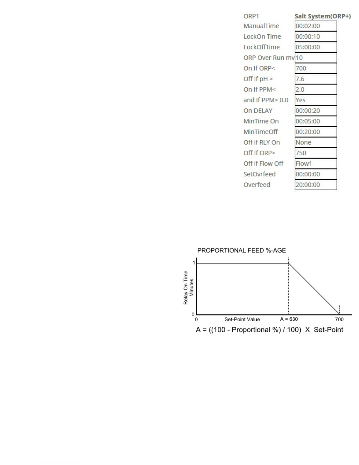
ORP1 and ORP2 Relay Configuration
In the Relay Setup Menu scroll down to the ORP1 or ORP2 relay and press
enter. The following lists all of the commands and what they do. The
command values can be changed, but the commands themselves are only
changed when changing the relay control type. When adding the TrueDPD
or updating the software that has updated commands the relay control type
must be updated for the list of commands to also be updated.
⧫ Manual Time 00:02:00: Is the amount of time you can set a relay to
turn on manually (Default Setting 2 Minutes). To turn the relay on
manually you have to do so in the service menu which will be covered
in the next section. When you turn on the relay manually in the service
menu, the relay will be on for 2 minutes in this case. To change the
time, simply enter the new time and hit the Enter Key to save.
⧫ LockOn Time 00:00:00: This setting is only located in the ORP Relay
menu. The factory default setting is zero “0”. This is a setting for when
the the ORP relay is in pH Lockout. It allows for some chlorine to feed
into the pool for the programmed time instead of none at all while the
relay is in pH Lockout. pH Lockout will be discussed in the Off If pH >
0.00 section. The “LockOffTime” below must be set as well to make
sure there is a period of off time during the day. You would have to
calculate how many gallons the pool would need in a day and then
calculate how long the feed pumps need to be On and Off during the
day to feed that amount.
⧫ LockOffTime 00:00:00: This is a setting for the off time of the cycle when the the ORP relay is in pH
Lockout. Both LockOn and LockOff allows for some chlorine to feed instead of none at all while the relay is
in pH Lockout.
⧫ ORP Over Run (for erosion feeders and salt systems): ORP Over Run allows for 0, 5, 10 or 15mv to be
added to the setpoint, it will turn on at the setpoint, and off at the setpoint plus this value.
⧫ Proportional 10% (for liquid CL): The Proportional
value (Default Setting 10%) means that as the
measured ORP reading gets to within 10% of the
ORP setpoint, the amount of relay on-time will
proportionally decrease as the reading gets closer
and closer to the setpoint. Proportional feed helps to
prevent chemical overshoot.
⧫ On If ORP < 700: This is the ORP set-point and the
factory default setting is 700. The relay will turn the
chemical feed pump on if the measured ORP
reading is less than 700.
⧫ Off If pH > 0.00: pH Lockout Command. The default setting is zero “0” or disabled. ORP is highly
dependant on pH. In other words, a high pH reduces the killing effectiveness of the sanitizer and has a
direct effect on lowering the ORP reading even though there may be an ample amount of sanitizer in the
water. pH Lockout helps to prevent chlorine overfeed. A typical pH Lockout setting is 8.0 and will lockout
the ORP relay when pH reaches 8.0 or higher. This command has been moved before the PPM control
command if the TrueDPD sensor is enabled to only effect control from the ORP sensor.
⧫ On If PPM < 2.0 (Requires TrueDPD sensor): This is the PPM set-point and the factory default setting is
2.0. The relay will turn the chemical feed pump on if the measured PPM reading is less than 2.0.
⧫ And if PPM> 0.0 (Requires TrueDPD sensor): The TrueDPD sensor will read a 0.0 level if out of DPD
reagent. Set this command to Yes if that is a possibility to not allow feeding with a 0.0 PPM level.
⧫ On Delay 00:00:20: The on delay, in this case 20 seconds, is necessary to prevent the relay and hence
the chemical feed pump from turning on and off frequently if the sensor measurement fluctuates back and
PoolWarden Manual www.poolwardentraining.com 530-205-4520 20
Page 21

forth from 699 and 700. It means that the relay will not turn on unless the condition of “On If ORP < 700” is
satisfied for at least 20 seconds - then the relay will turn on for the programmed “On Time 00:01:00” in this
case 1 minute. To change the on delay time, simply press Enter and change the time and press Enter
again to save the new setting. Enter 00:00:00 to disable.
⧫ On Time 00:01:00: This is the total amount of time the relay will be ON if the “On If ORP < 700” condition
has been satisfied. The default setting is 1 Minute. This command works in conjunction with the
MinTimeOff Command below. If the ORP reading is not being maintained then more or less on time may
be needed.
⧫ MinTimeOff 00:07:00: This is the total amount the relay will be OFF if the “On if ORP < 700” condition has
been satisfied. This is the amount of time allowed for chemical mixing in the pool and works in conjunction
with the “On Time” Command above. Do not set to 00:00:00 if the On Time is not also set to 00:00:00 as
they work together.
⧫ Off If RLY On -none: The default setting is none or disabled. This feature prevents 2 relays being on at
the same time. It means this ORP Relay will be Off if the pH relay is On. This is useful in cases where the
chemical injection points are very close together and prevents the ORP relay injecting at the same time the
pH relay is injecting. Simply press Enter to toggle through the selections.
⧫ Off if Flow Off - 1 or 3: The ORP Relay will be turned off if “No Flow”
for Pool1 and if “No Flow”
is detected in Flow Switch Input 3 for Pool2. Note: This setting can’t be changed
is detected in Flow Switch Input 1
as it relates to safety, pressing the Right Arrow to change has no effect.
⧫ SetOvrfeed 00:00:00: This type of overfeed requires the measurement to approach the setpoint. If a feed
tube is broken and the chemicals are going on the floor this type of overfeed protection will detect that and
shut down the relay sooner than the daily overfeed. Calculate how much feed time is required for the
setpoint to be reached when the sanitizer is at 0. When the Setpoint Overfeed is reached the relay status
will display an “s”. The default value is 00:00:00 which is disabled, in order to use this feature calculate the
amount of time required and enter that time.
❑When in Setpoint Overfeed, there are only 2 ways to reset it: 1) cycle power on the PoolWarden and 2)
Manually fix the chemical imbalance so that the setpoint is approached within 5%.
❑When feeding sanitizer the ORP measurement will rise as sanitizer is being added. When the ORP is
within 5% of the setpoint the Setpoint Overfeed timer will clear.
❑If it would take 2 gallons of liquid chlorine to raise the chlorine level from 0 to the desired value,
calculate how much time that would be, and enter the time. This time should be quite a bit lower than
the 24 hour Overfeed timer.
⧫ Overfeed 06:00:00: All chemical feed relays include this overfeed feature. The Overfeed time represents
the maximum amount of time a chemical relay will feed in a day from midnight to midnight. This must be
set up properly to reduce the chance of feeding large amounts of chemicals in the event something goes
wrong. The default time will most likely not be correct. Please follow the calculation below. The minimum
value for Overfeed time is 1 minute, it can’t be disabled.
❑Calculate the total amount of chemical the pool would ever need in a 24 hour period. (Example: 10
Gallons would be the MOST liquid chlorine a pool would need on any given day).
❑Calculate the amount of time it would take the feed-pump to inject that total amount of liquid chlorine in
a 24 hour period. Example: Limit to 10 gallons with a 50 Gallon Per Day (GPD) Fixed Rate Peristaltic
Pump. 10 Gallons / 50 Gallons * 24 Hours = 4.8 hours or 04:48:00. You will need to adjust for variable
pumps depending on the variable pump setting. Most variable pumps use a scale of 10 to 0. So if the
pump is set on 8 then use 80% of the total GDP rate, in this case .80 x 50 GPD = 40 GPD.
❑Calculate the overfeed time with the following equation using the following example…..
Overfeed Time = (Daily Gallon Maximum) / (Pump GPD Rate) times (24 Hours)
Round up and set the overfeed time. It can be set for minutes and seconds for finer control.
PoolWarden Manual www.poolwardentraining.com 530-205-4520 21
Page 22
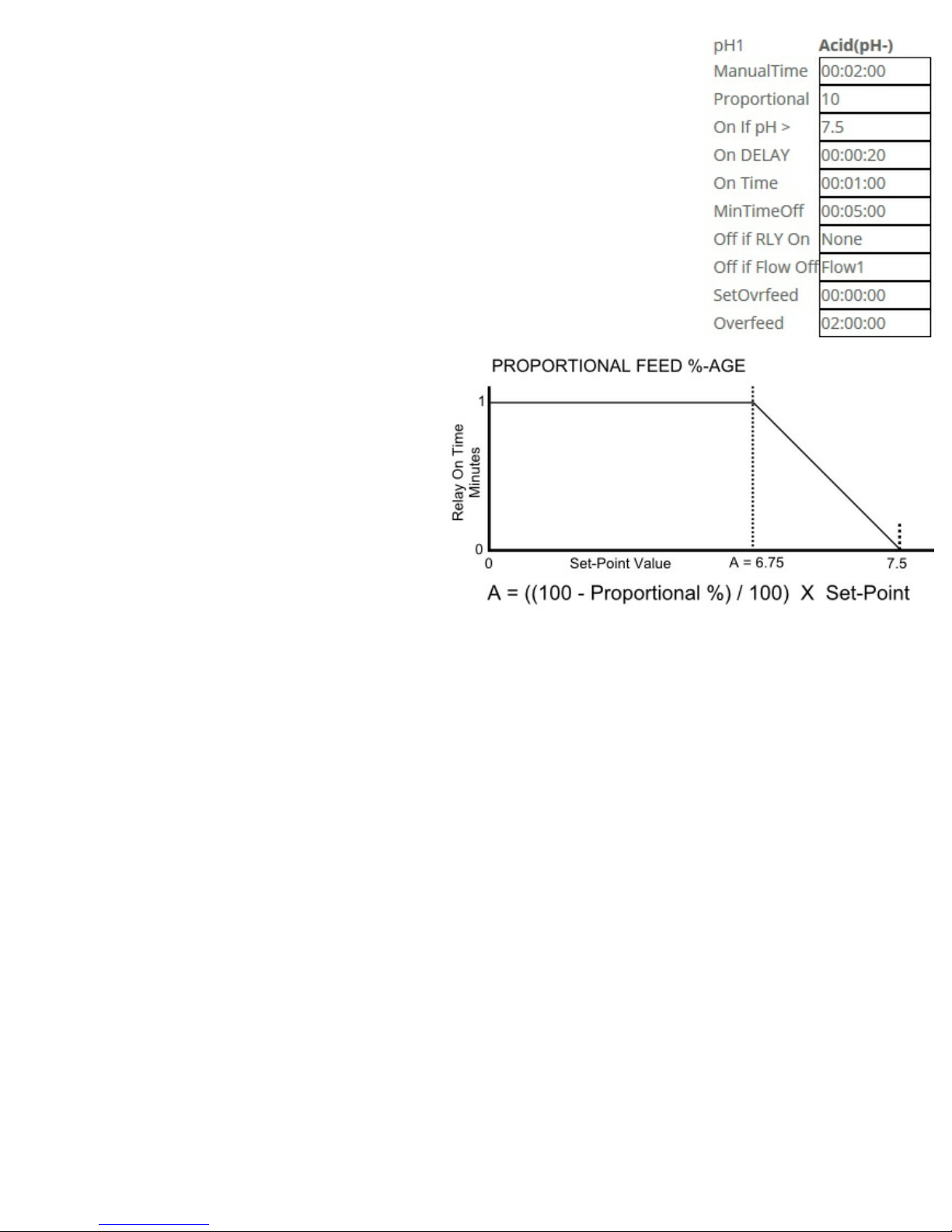
pH1 and pH2 Control Relays
In the Relay Setup Menu scroll down to pH1 or pH2 and press Enter. The
following reviews each command within a pH Relay selection that is set up as
Acid (change to base in the Relay control Types Menu). The other less common
control types such as Base follow a very similar relay programming and
command structure.
⧫ Manual Time 00:02:00: Is the amount of time you can set a relay to turn on
manually (Default Setting 2 Minutes). To turn the relay on manually you have
to do so in the service menu which will be covered in the next section. When
you turn on the relay manually in the service menu, the relay will be on for 2
minutes in this case. To change the time, simply enter the new time and
press Enter to save.
⧫ Proportional 10%: The Proportional %-Age
(Default Setting 10%) means that as the
measured pH reading gets to within 10%
(6.75 in this case) of the pH setpoint of 7.5,
the amount of relay on-time will
proportionally decrease as the reading gets
closer and closer to the setpoint.
Proportional feed helps to prevent chemical
overshoot. To change the %-Age, simply
press Enter, change the value and press
Enter to save the new setting. To deactivate
this feature set the %-Age to zero “0” and
press Enter to save setting.
⧫ On If pH > 7.5: This is the pH set-point and the factory default setting is 7.5. The relay will turn the
chemical feed pump on if the measured pH reading is greater than 7.5. The relay will turn on for the
programmed on time, in this case for 1 minute as set in the “On Time 00:01:00” command or less than 1
minute if the measured reading is within the proportional feed %-age of 10%. When feeding base, this
command is the only difference and will be On if pH < 7.5.
⧫ On Delay 00:00:20: The on delay, in this case 20 seconds, is necessary to prevent the relay and, hence
the chemical feed pump, from turning on and off frequently if the sensor measurement fluctuates back and
forth from 7.5 and 7.6. It means that the relay will not turn on unless the condition of “On If pH > 7.5” is
satisfied for at least 20 seconds - then the relay will turn on for the programmed “On Time 00:01:00” in this
case 1 minute. To change the on delay time, press Enter and change the time, press Enter to save the
new setting. The value 00:00:00 disables the on delay.
⧫ On Time 00:01:00: This is the total amount of time the relay will be ON if the “On If pH > 7.5” condition
has been satisfied. The default setting is 1 minute. This command works in conjunction with the
MinTimeOff Command below. If the pH reading is not being maintained then more or less on time may be
needed.
⧫ MinTimeOff 00:05:00: This is the total amount of time the relay will be OFF if the “On if pH > 7.5”
condition has been satisfied. This is the amount of time allowed for chemical mixing in the pool and works
in conjunction with the “On Time” Command above.
⧫ Off If RLY On -none: The default setting is none or disabled. This feature prevents 2 relays being on at
the same time. It means this pH Relay will be Off if the ORP relay is On. This is useful in cases where
the chemical injection points are very close together and prevents the pH relay injecting at the same time
the ORP relay is injecting. Simply press Enter to toggle through to the choices.
PoolWarden Manual www.poolwardentraining.com 530-205-4520 22
Page 23

⧫ Off if Flow Off - 1 or 3: The pH Relay will be turned off if “No Flow” is detected in Flow Switch Input 1 for
Pool1 and if “No Flow”
is detected in Flow Switch Input 3 for Pool2. Note: This setting can’t be changed as
it relates to safety, pressing the Right Arrow to change has no effect.
⧫ SetOvrfeed 00:00:00: This type of overfeed requires the measurement to approach the setpoint. If a feed
tube is broken and the chemicals are going on the floor this type of overfeed protection will detect that and
shut down the relay sooner than the daily overfeed. Calculate how much feed time is required for the
setpoint to be reached when the pH is a full point off. When the Setpoint Overfeed is reached the relay
status will display an “s”. The default value is 00:00:00 which is disabled, in order to use this feature
calculate the amount of time required and enter that time.
❑When in Setpoint Overfeed, there are only 2 ways to reset it: 1) cycle power on the PoolWarden and 2)
Manually fix the chemical imbalance so that the setpoint is approached within 5%.
❑When feeding acid the pH measurement will lower as acid is being added. When the pH is within 5% of
the setpoint the Setpoint Overfeed timer will clear.
⧫ Overfeed 06:00:00: All chemical feed relays include this overfeed feature. The Overfeed time represents
the maximum amount of time a chemical relay will feed in a day from midnight to midnight. This must be
set up properly to reduce the chance of feeding large amounts of chemicals in the event something goes
wrong. The default time will most likely not be correct. Please follow the calculation below.
❑Calculate the total amount of chemical the pool would ever need in a 24 hour period. (Example: 10
Gallons would be the MOST chemical a pool would need on any given day).
❑Calculate the amount of time it would take the feed-pump to inject that total amount of chemical in a 24
hours. Example: Limit to 1 gallon with a 10 Gallon Per Day (GPD) Fixed Rate Peristaltic Pump. 1
Gallons / 10 Gallons * 24 Hours = 2.4 hours or 02:24:00. You will need to adjust for variable pumps
Alarm 1 and 2 Setup
In the “Relay Setup” menu are also the configuration settings for the alarm
light on the PoolWarden enclosure lid. In the Relay Setup Menu simply scroll
down to the Alarm1 or Alarm2 and press Enter. The following reviews each
command within an Alarm Menu Selection.
⧫ On If ORP > 800: The factory default setting is 800. The alarm will turn
on if this condition is satisfied. To change the condition simply hit the
Enter Key to enter a new value and hit the Enter Key again to save or
enter “0” zero to disable.
⧫ On if ORP < 600: The factory default setting is 600. The alarm will turn
on if this condition is satisfied. To change the condition simply hit the
Enter Key to enter a new value and hit the Enter Key again to save or
enter “0” zero to disable.
⧫ On If pH > 8.0: The factory default setting is 8.0. The alarm will turn on if
Alarm 1 or 2 Selected
On If ORP > 800
On If ORP < 600
On If pH > 8.0
On If pH < 7.0
On If Temp > 0
On If Temp < 0
On If Flow Off - none
On If Overfeed - YES
Off If Flow Off - none
On Delay 00:10:00
MinTime On 00:00:10
MinTimeOff 00:00:10
Off If Time < 00:00:00
Off If Time > 00:00:00
this condition is satisfied. To change the condition simply hit the Enter
Key to enter a new value and hit the Enter Key again to save or enter “0”
zero to disable.
⧫ On If pH < 7.0: The factory default setting is 7.0. The alarm will turn on if this condition is satisfied. To
change the condition simply hit the Enter Key to enter a new value and hit the Enter Key again to save or
enter “0” zero to disable.
⧫ On If Temp > 0: The factory default setting is “0” zero or disabled. The alarm will turn on if this
condition is satisfied. To change the condition simply hit the Enter Key to enter a new value and hit the
Enter Key again to save.
⧫ On If Temp < 0: The factory default setting is “0” zero or disabled. The alarm will turn on if this
condition is satisfied. To change the condition simply hit the Enter Key to enter a new value and hit the
Enter Key again to save.
⧫ On If Flow Off - none: The factory default setting is “none” or disabled. The alarm will turn on if no flow
is detected. Please Remember: Pool1 uses Flow Switch Input 1 or 2 (Default is 1) and Pool2 uses Flow
PoolWarden Manual www.poolwardentraining.com 530-205-4520 23
Page 24

Switch Input 3 or 4 (Default is 3). To turn the alarm status on if no flow is detected for Pool1 simply hit
the Enter Key to change the value from “none” to 1 (Flow Switch Input 1) and hit the Back key to save.
To turn the alarm status on if no flow is detected for Pool2 simply hit the Enter Key 3 times to change the
value from “none” to 3 (Flow Switch Input 3) and hit the Back key to save.
⧫ On If Overfeed - YES: The factory default setting is “YES”. The alarm will turn on if this condition is
satisfied. To change the condition simply hit the Enter Key to change to NO and hit the Back Key to
save.
⧫ Off If Flow Off - none: The factory default setting is “none” or disabled. The PoolWarden will not send
alarm notification if no flow is detected. Please Remember: Pool1 uses Flow Switch Input 1 or 2
(Default is 1) and Pool2 uses Flow Switch Input 3 or 4 (Default is 3). To turn the alarm status on if no
flow is detected for Pool1 simply hit the Enter Key to change the value from “none” to 1 (Flow Switch
Input 1) and hit the Back key to save. To turn the alarm status on if no flow is detected for Pool2 simply
hit the Enter Key 3 times to change the value from “none” to 3 (Flow Switch Input 3) and hit the Back key
to save.
⧫ On Delay 00:10:00: The factory default setting is 10 Minutes. The alarm will only turn on if this
condition is satisfied for at least 10 Minutes. This command prevents multiple alarms if the sensor
reading is fluctuating back and forth. To change the command simply hit the Enter Key to enter a new
value and hit the Enter Key again to save or enter “0” zero to disable.
⧫ Off If Time < 00:00:00: This is a time of day command. The factory default setting is “0” zero or
disabled. All alarm conditions will be OFF for the entire time of day until the time of day condition is met.
If not 00:00:00, the alarm will be off from midnight until the time in this command.
⧫ Off If Time > 00:00:00: This is a time of day command. The factory default setting is “00:00:00” or
disabled. If not 00:00:00, the alarm will be OFF for the indicated time until midnight.
Alarm control types:
❑Standard: This is listed above and uses ORP values to set the alarm. Use this control type for the
alarms if ORP Calibration is enabled in the “System Menu”.
❑ORP %: When the ORP Calibration is disabled the sanitizer levels are changed by changing the ORP
setpoint. If the ORP setpoint is changed then the alarm values for ORP may also need to be changed
to reflect this. Using the ORP % for the alarm control type uses a percentage of the setpoint rather
than specific values so if the ORP setpoint is changed that is automatically reflected in the ORP part
of the alarms. The default value is 10%, if the ORP setpoint is 700, then the alarm values would be
630 and 770 mv.
PoolWarden Manual www.poolwardentraining.com 530-205-4520 24
Page 25
Step 5 - Service Menu
The Service Menu includes all items that a service technician needs to
service a pool and is a critical next step in setting up PoolWarden. From the
Default Readings Screen simply press the Back button to access the main
menu and select the first line “Service” and press the Enter button to access
the Service Menu. From here you will be able to manually turn on and off all
relays, calibrate pH and ORP sensors, disable the relays for servicing and
clear all the overfeed timers.
Relay Manual
Calibration P1
Calibration P2
Disable Relays
Clear Overfeed
TrueDPD PPM Manual
⧫ Relay Manual Mode: Use the up and down arrow keys to scroll next to
DPD Level 55%
the relay that needs to be put into manual mode. Press the Enter button
or the Right Arrow to put the selected relay into manual mode. There are
three states that the relay can be in when in manual control:
PH 1 00:00:00 OFF
❑ If the relay is currently ON, it will turn off for the amount of manual
relay time in the relay setup. Once this time is finished the relay will go
back to auto.
❑If the relay is OFF, and not in manual OFF mode, it will turn ON for the
manual relay time and return to auto.
If the relay is OFF, and not manual mode, it will go back to auto.
⧫ Calibration Pool1 and Pool2: Select the desired pool to calibrate and
ORP 1 00:00:00 OFF
Aux 1 00:00:00 OFF
Aux 2 00:00:00 OFF
PH 2 00:00:00 OFF
ORP 2 00:00:00 OFF
Aux 3 00:00:00 OFF
Aux 4 00:00:00 OFF
scroll to the item to calibrate. Manual Pool Measurements must be taken
to calibrate each sensor. For best results the pool should be at the desired
values when calibrating. The percentage to the right of the current reading
is the amount of calibration and if it is at 99% that sensor is at the
maximum calibration and may need to be replaced.
Cal ORP1 650 -16%
Cal pH1 7.7 -5%
Cal Temp1 78 +12%
❑pH: Enter the manually measured pH value. A pH sensor can be
calibrated +/- 2 pH units.
❑ORP: If the sanitizer level is higher than desired and the pH is at the
setpoint then raise the ORP calibration slightly. If the sanitizer level is
lower than desired and the pH is at the setpoint then lower the ORP
Clear Cal ORP1
Clear Cal pH1
Clear Cal Temp1
Cal PPM1 3.4 -6%
Clear Cal PPM1
calibration slightly. The ORP sensor can be calibrated +/- 200 mV.
ORP sensors are affected by cyanuric acid, pH and other factors and it
may take a few days to get it adjusted.
❑Temperature: Enter the manually measured temperature. A temperature sensor can be calibrated +/-
25 degrees Fahrenheit.
❑PPM: If the TrueDPD is connected there will be a selection for calibrating the free chlorine. When it is
calibrated, the calibration is calculated on the next measurement cycle, if the PoolWarden power is
cycled before that happens the calibration will be lost.
Disable Relays: To make sure the chemical feeders do not turn on while servicing a pool. Press Enter up
to 4 times to disable from 15 minutes to 60 minutes. Press the Enter key again to put the relays back to
auto.
Service Menu
Relay Manual
Calibration
⧫ Clear Overfeed Times: If an overfeed timer has been reached it will only clear/reset at midnight. There
are times when servicing a pool that you may want to clear the overfeed timers to stop an alarm from
tripping or to have the relay turn back on.
❑The only way to clear the overfeed timers is to select Clear Overfeed in the “Service” menu or to wait till
midnight when they automatically clear. Note: Cycling power on the PoolWarden will not clear the
overfeed timers.
❑The Setpoint Overfeed timers are not cleared when selecting the Clear Overfeed Times.
⧫ TrueDPD Manual: If the TrueDPD is connected, this menu allows for manually controlling all of the
functions of the TrueDPD which is useful to make sure everything is working properly and purging the
DPD.
⧫ DPD Level 55%: Displays the current DPD level. Press enter to change the value in 10% increments.
PoolWarden Manual www.poolwardentraining.com 530-205-4520 25
Page 26
COMMUNICATION - GETTING STARTED: LAN / ETHERNET
PoolWarden will support communication with a data server utilizing an
optional Ethernet / LAN communication module to connect to a pool facilities
network. The following section describes how a LAN Communication module
is set up in PoolWarden in order to connect to a network with all the
configuration steps necessary to successfully establish communication. If
there isn’t an Ethernet connection in close to the PoolWarden one of the
following options may be required:
⧫ WIFI: An Ethernet to WIFI bridge can be purchased to enable WIFI. Follow the instructions that come
with the bridge to set it up.
⧫ Ethernet over Power Line: This approach works very well with very little to configure. Make sure the
adapters are not plugged into a power strip. Follow the instruction that come with the bridge to set it up,
there will be one in the router room, and one in the PoolWarden room.
⧫ Cellular: This approach works very well but adds to the initial cost and the yearly cost as there is a
cellular company monthly charge.
⧫ NOTE: If the Ethernet cable is plugged in when the PoolWarden is on it will not try to establish the
connection. Always cycle power on the PoolWarden as the connection process only occurs at startup.
Data Server Setup
Network Setup
Information
Email
Client IP Security
Network Setup
Step 1 - The Communication Module
When the PoolWarden turns on it will automatically detect the PW-LAN if
installed. The PoolWarden will first obtain the IP address of the data server
and during this process displays an “N” (not connected) in the lower right
corner of the display screen. Once the IP address is obtained the “N” will
change to a “c” (connected) in the lower right corner.
DHCP: Enabled
Automatic connection
with dynamic IP
Address assignment
DHCP Enabled
Step 2 - Network Setup Menu
If only the data server feature will be used no changes are required, leave
DHCP enabled. If the direct connection feature is also needed then DHCP may
need to be disabled to configure the PoolWarden with a local static IP
address.
DHCP: Stands for “Dynamic Host Configuration Protocol”. The default setting
is “Enabled”. When DHCP is enabled the network located at the pool facility
will automatically assign an IP address to the communication module within
PoolWarden. When enabled, there is nothing else to configure. This is also a
convenient way to find an available local IP address. Once assigned by the
local network it can then be switched to a static IP address with the came
value that can be observed in the Communication / Information screen.
DHCP Disabled: When disabled the following items must be correctly entered and will be provided by the
IT department at the facility.
❑Static IP Address: Used for connecting to PoolWarden remotely.
❑Gateway IP Address: Used for connecting to PoolWarden remotely.
❑Subnet Mask: Default is 255.255.255.0 and does not need to be changed.
DHCP Disabled
DHCP: disabled
Static IP Address
192.168.0.199
Gateway IP Address
192.168.0.1
Subnet Mask
255.255.255.0
Primary DNS
8.8.8.8
Step 3 - Client IP Security
You can enter up to 10 IP addresses which provide enhanced security for remote connections to the
PoolWarden. When IP addresses are added, remote connections will only be allowed if the client IP
address is on this list. This works for both remote and local IP addresses. You can also allow a range by
using 255 as a mask. For example:
192.168.0.255 will allow all access from 192.168.0.(0 to 255).
PoolWarden Manual www.poolwardentraining.com 530-205-4520 26
Page 27
If not using direct connect enter 1.1.1.1 as the first IP address for Client IP
Security, this will disable any unexpected communication with the
PoolWarden. When not on the list the connection is rejected and it will
appear that it isn’t even there.
Step 4 - DATA SERVER SETUP
Set the interval that the PoolWarden will send a data packet to the server. If
the interval is 00:00:00 data will not be sent. Select Send Data Packet to
immediately send a data packet. To disable sending data packets at night
set a start and end hour.
Step 5 - INFORMATION
The information screen contains the IP address that the PoolWarden is using
and the gateway IP address. The Mac value is also provided and the IT
configuration may want to setup the routing using the Mac address. If they
ask for this information it is available on this screen as well as on a sticker on
the bottom of the PW-LAN card.
The Ver (software version) of the PW-LAN card is also displayed.
Step 6 - EMAIL
The ability for the PoolWarden to send up to 4 emails has been implemented
from PW-LAN version 12 and up. For lower versions Email will not send
even though you can enter email addresses. The opening Email screen lists
the 4 email addresses. To edit, position the cursor on the one to modify and
press the Right Arrow or the Enter button.
Send on Alarm: Set to Yes to send an email when there is an alarm
condition. An alarm email is only sent when the alarm turns on.
Send Now: Select to send an email right now for testing.
Email Address: The PoolWarden supports up to 30 characters and only
part of the address in displayed on the screen. When editing the address will
use two lines.
Send Hour 1-3: You can enter up to 3 different times to automatically have
the PoolWarden send a data email.
Data Server Setup
Send Data Packet
Interval: 00:00:00
Start Hour: 0
End Hour: 0
On Alarm: No
Information
Pkts:82 Ver 12
IP 198.168.0.200
GIP 198.168.0.1
Mac00:12:34:56:78:9A
Email
Email Settings
Send on Alarm: Yes
Send Now
[email protected]
Send hour1 :13
Send hour2 :13
Send hour3 :14
Edit Email Address
Support@controlomati
c.com
Upper Case ^-Del
V-cancel Back-Ins
COMMUNICATION: REMOTE CONNECTION
The PoolWarden is a web server and can be connected to any web browser which can be a computer,
laptop, smart phone or any device with an Internet connection and a browser. To make the connection to
the PoolWarden the router at the facility will need to be setup appropriately to route outside connections to
the appropriate PoolWarden.
The web browser will display a representation of the PoolWarden including the display and buttons with the
ability to retrieve the configuration and the internally recorded data. In order to access the main menu to
make any configuration changes Security must be enabled, if it isn’t the main menu is disabled.
PoolWarden Manual www.poolwardentraining.com 530-205-4520 27
Page 28
ADVANCED FEATURES
The rest of this manual will be dedicated to all of the Advanced Menus & Features which make PoolWarden
one of the most versatile chemical controllers in the world. Please review each section carefully to
understand each menu item. Simply press the Back button from the Default Readings Screen to gain
access to the “Main Menu”. Use the Up & Down Arrows to navigate to each sub menu item and press
enter to go to that sub menu or selection. Accessing the Main Menu can be password protected and can
be dependent on a security level if PoolWarden is security enabled in the “Security Setup” menu which was
covered in the “PROGRAMMING - GETTING STARTED” section of this manual.
Default Readings Screen
m
Data Recording
Go To Data
Interval 01:00:00
Clear Data
Used: 808/8192
Serial Printer
Print Data
Print: Off
Print Last 7
ORP pH Tf Flow
v
681b7.7 75 ON a
695p7.5 102 ON
RlyP1↑↓o_ P2_↓o_
Back
Press
Back Key
Main Menu
ADVANCED
MENU
Advanced
Edit: 7=1st, 9=2
Time Profile 1
Sunday :0<24
Monday :0<24
Tuesday :0<24
Wednesday:0<24
Thursday :0<24
Friday :0<24
Saturday :0<24
Time Profile 2
Sunday :0<24
Monday :0<24
Tuesday :0<24
Wednesday:0<24
Thursday :0<24
Friday :0<24
Saturday :0<24
ORP Cya Calibration
Dawn Hour 0 AM
Dusk Hour 0 PM
ORP1 Night Cya -0
ORP2 Night Cya -0
nd
Service LAN
Data Security
Relays Relay Type
Advanced System
System
Time: 12:36:17
Date: 03/27/15
Day : Friday
Backlight Time 500
Name: PoolWarden
Units: English
Flow Menu
ORP Cal: Enabled
PoolWarden (Dual)
Daylight Savings No
Langelier pH +/-0.2
TrueDPD: Dual
TrueDPD Cycle:10 min
Service QuickJmp On
Display Type: VFD
Clear/Reset Menu
Overlay Color White
Scroll Readings OFF
PoolWarden Manual www.poolwardentraining.com 530-205-4520 28
Page 29

Data Recording Menu
This menu provides access to PoolWarden’s internally recorded data. The
data can be displayed visually on screen. Please note that this screen will only
display readings, pH, ORP, Temp, Flow Status and Alarm Status. The internal
memory has the ability to record 8,192 rows of data. Once the maximum
memory has been reached, any new data will record over the oldest data. To
access “Data Recording” simply press the Back button from the default
readings screen and scroll down to “Data Recording” and press Enter and
select “Go To Data”.
⧫ Go To Data: Before entering the actual Data a “Data Help” screen is
displayed that provides a brief summary of the tips on how to scroll through
the rows of recorded data.
❑0 Toggle line4: Pressing the Zero 0 button toggles line 4 on the display
screen between the relay status for each reading and the Date, Time &
Data Record Number.
❑#*10 Big Jump: This is the “Big Jump” by a factor of 10. If you press any number 1 through 9 and
then the Up or Down Arrow it will jump through the data by a factor of 10 times that number.
Example: If you press 8 then the up arrow it will jump forward through 80 rows (8 x 10 = 80) of data.
If you press 7 then the down arrow it will jump backward through 70 rows (7 x 10 = 70).
❑Back - > Quit: Exit the Data and bring you back to the Data Recording screen.
❑↑+big: Pressing the Up Arrow will jump forward 30 rows of data. The up arrow also works in
conjunction with the #*10Big Jump above. If any number between 1 through 9 is pressed followed by
the up arrow then it will jump the data by a factor of 10 times that number.
❑> +1: Pressing the Right Arrow will move forward one “1” data row at a time.
❑< - 1: Pressing the Left Arrow will move backward one “1” data row at a time.
❑↓-big: Pressing the Down Arrow will jump forward 30 rows of data. The up arrow also works in
conjunction with the #*10Big Jump above. If any number between 1 through 9 is pressed followed by
the down arrow key then it will jump the data by a factor of 10 times that number.
⧫ Interval 00:00:00: Set the data recording time interval. The default setting is 00:00:00 or disabled.
Simply press Enter to scroll through the following data recording intervals.
Data Recording
Go To Data
Interval 01:00:00
Clear Data
Used: 808/8192
Serial Printer
Print Data
Print: Off
Print Last 7
Go To Data
Data Help ↑+big
0 Toggle line4 > +1
#*10 Big Jump < -1
Back -> Quit ↓-big
❑00:00:00: Disabled, No Data Recording
❑00:05:00: Data will record in 5 minute intervals. Internal Memory will be full in 5.5 Days.
❑00:15:00: Data will record in 15 minute intervals. Internal Memory will be full in 85 Days.
❑00:30:00: Data will record in 30 minute intervals. Internal Memory will be full in 170 Days.
❑01:00:00: Data will record in 1 hour intervals. Internal Memory will be full in 341 Days.
⧫ Clear Data: Simply scroll down to “Clear Data” and press Enter and the internal memory will reset to
0/8192.
⧫ Used 0 / 8192: This shows how much internal memory is currently being used. If a number like
3150/8192 is seen in this screen, then that means 3150 rows of data have been recorded out of the
available 8192 rows. Press Enter to immediately record data. If there is a lower case “o” on the fourth
line then the data is in overflow mode and any new recorded data is erasing the oldest recorded data.
Serial Printer
If the serial printer is connected it will be automatically detected and enable the additional menu choices in
the Data Recording menu. When the PoolWarden is turned on, as part of the startup process the serial
printer will be listed after about 10 seconds, if it isn’t listed make sure the printer is turned on and the wires
are correctly connected on the PoolWarden connector. The serial printer must be turned on before the
PoolWarden.
Once a day a header line will print with the name of the PoolWarden (setup in the System Menu) and the
serial number. Then at the appropriate intervals the current measurements will be printed.
⧫ Serial Printer: This line is information only. All items after it are for the serial printer.
PoolWarden Manual www.poolwardentraining.com 530-205-4520 29
Page 30

⧫ Print data: Print the current measurements now.
⧫ Print: Selections are OFF, Every Hour and NOON
⧫ Print Last 7: Prints the last 7 noontime measurements that are also displayed in the Handy Menu. There
may be less than 7 if the measurements haven’t been made yet or if the PoolWarden was turned off at
NOON on some of the days.
System Menu
The System Menu is where many of the main operating system features are
turned on or off. Please review and set each item according to your needs. To
access the System Menu press Back from the “Default Readings Screen” and
scroll down the Main Menu to System and press Enter.
⧫ Time: The time clock in PoolWarden is based on 00:00:00 military time.
Simply press Enter and set the correct time and press Enter again to save
the new time.
⧫ Date: Simply press Enter and set the correct date and press the Enter key
again to save the new date.
⧫ Day: Press the Enter key to toggle through to the appropriate day of the
week and press the Back key to save the new day of the week.
⧫ Backlight Time: This is where the Backlight timer can be changed to
preset times of 120, 180, 500 or 1000 seconds. This is the time
PoolWarden will stay in a current menu before PoolWarden times-out since
the last key was pressed and reverts back to the “Default Readings Screen”
and resets the password entry status. The default setting for the Backlight
timer is 120 seconds. To change, simply press Enter to cycle through the
Time: 12:36:17
Date: 03/27/15
Day : Friday
Backlight Time 500
Name: PoolWarden
Units: English
Flow Menu
ORP Cal: Enabled
PoolWarden (Dual)
Daylight Savings No
Langelier pH +/-0.2
TrueDPD Menu
Service QuickJmp On
Display Type: VFD
Clear/Reset Menu
Overlay Color White
Scroll Readings OFF
System
preset times then press the Back key to save the new time.
⧫ Name: Press Enter to change the name for the PoolWarden. This could be the name of the location or
any name of choice. This name will be sent to the data server if communication is enabled and printed
as the header line if there is a serial printer.
⧫ Units: Press Enter to toggle between the English or Metric System.
⧫ Flow Menu: Press Enter to enter the flow sensor setup screen. Select for each of the 4 flow inputs a
standard on/off flow switch or a digital flow meter if one has been installed. If “Digital” is selected, then
scroll down to “Flow# Scale” and enter the K-Factor (pulse / gallon) for the Digital Flow Meter and press
Enter to save the new setting. When switching to Digital or to a switch, PoolWarden must be shut down
and restarted for the change to take effect. If the TrueDPD is connected flow 4 can’t be changed.
⧫ ORP Cal: Press Enter to Enable or Disable ORP Calibration. The default setting is Enabled. If disabled
the ORP will not be able to be calibrated and any changes in sanitizer level require changing the
setpoint.
⧫ PoolWarden (Dual): This setting is normally entered by the factory when PoolWarden is purchased.
However, there may be a need to set PoolWarden to Single Pool Controller or Dual Pool Controller.
⧫ Daylight Savings: Press Enter to toggle between YES to enable daylight savings time or NO to disable
daylight savings. The default setting is set to YES which means that PoolWarden will automatically
adjust for daylight savings time each year.
⧫ Langelier pH +/- 0.0: When the Langelier Index falls outside of the balanced range of -0.5 to +0.5, the
pH set-point within PoolWarden will be adjusted by this pre-set factor to help keep the Langelier Index
within the range of -0.5 to +0.5 (Balanced). To change the Langelier pH adjustment factor, simply press
Enter to toggle through +/- 0.0, +/- 0.1, +/- 0.2 or +/- 0.3. The set-point within PoolWarden will be
adjusted by this Langelier Index Adjustment Factor once the pH sensor reading has reached the existing
set-point. To view the Langelier Index simply press the Right Arrow twice from the “Default Readings
Screen”. To perform a quick view of the current set-points simply press the 9 button when at the “Default
PoolWarden Manual www.poolwardentraining.com 530-205-4520 30
Page 31

Readings Screen”. Langelier is enabled after manual measurements have been entered in the “Handy
Menu”.
⧫ TrueDPD Menu: If the optional TrueDPD PPM sensor is connected then use this menu to set up how it
operates.
TrueDPD PPM: Pool1 - Select if Pool1, Pool2, Both or none.
⧫ TrueDPD Cycle: The is the cycle time between measurements and
can be set to 5, 10, 15, 30 and 60 minutes.
⧫ Reagent: Liquid/Powder - The TrueDPD supports two different
reagents for making the measurement. The standard powder mix is
TrueDPD PPM: Pool1
TrueDPD Cycle: 5 min
Reagent: Liquid
Skip A Cycle:None
TrueDPD Menu
low cost, accurate but darkens over time at higher temperatures.
The Liquid DPD that is made from Lamotte doesn’t require mixing
with water and doesn’t darken over time.
⧫ Service QuickJmp: When set to ON, pressing the Left Arrow from the ‘Default Readings Screen” will
jump to the “Service“ menu without requiring a password even if security is enabled. Pressing Back will
return to the “Default Readings Screen” and not the “Main Menu”. Press 2 or 3 to access the setpoint and
mixing time entery for ORP and pH. Pressing 2 or 3 are password protected.
⧫ Display Type: VFD: Press Enter to cycle between VFD and LCD. The default display is the LCD type.
⧫ Clear/Reset Menu: To clear all calibrations, reset everything to factory
Clear / Reset Menu
defaults or to reset the monthly timers. This menu is available as the last
selection in the System Menu.
Clear/Reset Menu
This Month On Times
⧫ This Month On Times: PoolWarden keeps track of the total “ON” times
for each relay for a running two month period. To clear the total “ON”
times for the current month select “This Month On Times” and press
Enter to clear
Last Month On Times: PoolWarden keeps track of the total “ON” times
Last Month On Times
All Calibrations
Energy Management
Flow Totalizers
Reset Everything
for each relay for a running two month period. To clear the total “ON”
times for last month select “Last Month On Times” and press Enter.
⧫ All Calibrations: Clear all calibrations including pH, ORP and temperature, select “All Calibrations”
and press Enter to clear.
⧫ Energy Management: To reset to factory defaults all energy management settings within the
“Advanced” Menu select “Energy Management” and press Enter to clear. More will be covered on
Energy Management in the Advanced Menu section of this manual.
⧫ Flow Totalizers: To clear the volume readings in the Flow Menu if a Digital Flow meter is installed
select “Flow Totalizers” and press Enter to clear.
⧫ Reset Everything: To Reset all settings back to factory defaults. This clears all calibrations and sets
the relays back to the default control types. When selected, a Warning screen will display and you must
press 9 to proceed or any other button to exit without resetting everything.
⧫ Overlay Color: White or Blue. The numbers and arrows work the same for both, the letters and symbols
below the numbers are different for both overlays.
⧫ Scroll Readings: OFF or ON. When set to ON, when the PoolWarden goes to the default reading screen it
will instead scroll through the last 7 noontime readings at a 5 second interval for each day. If the health
department is doing an inspection and the data hasn’t been transferred to the log the readings can be
viewed on the PoolWarden without needing to touch a button.
Advanced Menu (Energy & CYA Management)
This menu includes items that are not required for the normal operation of PoolWarden and are considered
advanced features.
⧫ Time Profile 1 and 2: The Time Profiles section of the Advanced menu works in conjunction with setting
up one of the Auxiliary Relays in the Relay Control Type menu to “Heater” and then creating Temperature
PoolWarden Manual www.poolwardentraining.com 530-205-4520 31
Page 32

Set-points in the Relay Setup menu. The Time Profiles allow for using the
Advanced
night time setpoint at different times of each day. Zero “0” and Twenty Four
“24” are the default settings for each day and mean the time settings are
disabled in this menu. Simply scroll down to the day and press the Seven “7”
key to change the first time or the Nine “9” key to change the second time.
The time is based on a 24-Hour Military Time.
Edit: 7=1st, 9=2
Time Profile 1
Sunday :0<24
Monday :0<24
Tuesday :0<24
❑Example: This represents an example if the Auxiliary 1 Relay is set to
“Heater” control type and the main Aux1 Relay Set-point is set to “On if
Temp < 80” and the secondary Set-point is set to “Night Temp < 70”. On
Sunday in the Advanced Menu change the first number “0” to “6”
(6:00am) and the second number “24” to “18” (6:00pm). This means that
the main set-point of “On if Temp < 80” will be followed when the time is
between 6:00am or 6:00pm on Sunday. If the time is less than 6:00am or
more than 6:00pm on Sunday then the secondary set-point of “Night
Temp < 70” will be followed.
Wednesday:0<24
Thursday :0<24
Friday :0<24
Saturday :0<24
ORP Cya Calibration
Dawn Hour 0 AM
Dusk Hour 0 PM
ORP1 Night Cya -0
Reset All Advanced
⧫ ORP Cya Calibration: Allows for the ORP to be reduced during night time
hours to adjust for the natural ORP increase during the evening hours if
Cyanuric Acid is being used in the Pool. Simply set the Dusk and Dawn hour (0 to 24 Hour Military Time)
to when the sun rises and sets. Then enter the ORP Millivolt Adjustment Number in “ORP# Night Cya -0”
that the pool normally experiences at night. What usually happens in this case is at night the ORP rises
and PoolWarden will not feed any more sanitizer until the sun comes up the next day, but during the night
the actual chlorine dropped so in the morning the chlorine level may be low. Lowering the ORP value at
night will allow for sanitizer to still be fed even in the presence of cyanuric acid. In order to set this value
observe the ORP reading at noon and midnight with the same sanitizer level, if the cyanuric acid had no
impact the ORP values would be the same. Subtract the midnight ORP reading from the noon ORP
reading and this is the value that can be entered, enter a number less to be conservative.
nd
❑Example: If the pool normally experiences a 125 Millivolt Increase between the hours of 7:00pm and
6:00am then enter “6” for the Dawn hour, 19 for the Dusk hour and 125 in “ORP Night Cya -125”, to
be conservative enter 75 instead of 125. PoolWarden will now adjust the ORP Reading by -125
Millivolts to normalize the reading during the night time hours.
⧫ Reset All Advanced: Reset all the Advanced Menu settings back to the default settings which disables
this menu unit new settings are entered.
PoolWarden Manual www.poolwardentraining.com 530-205-4520 32
Page 33
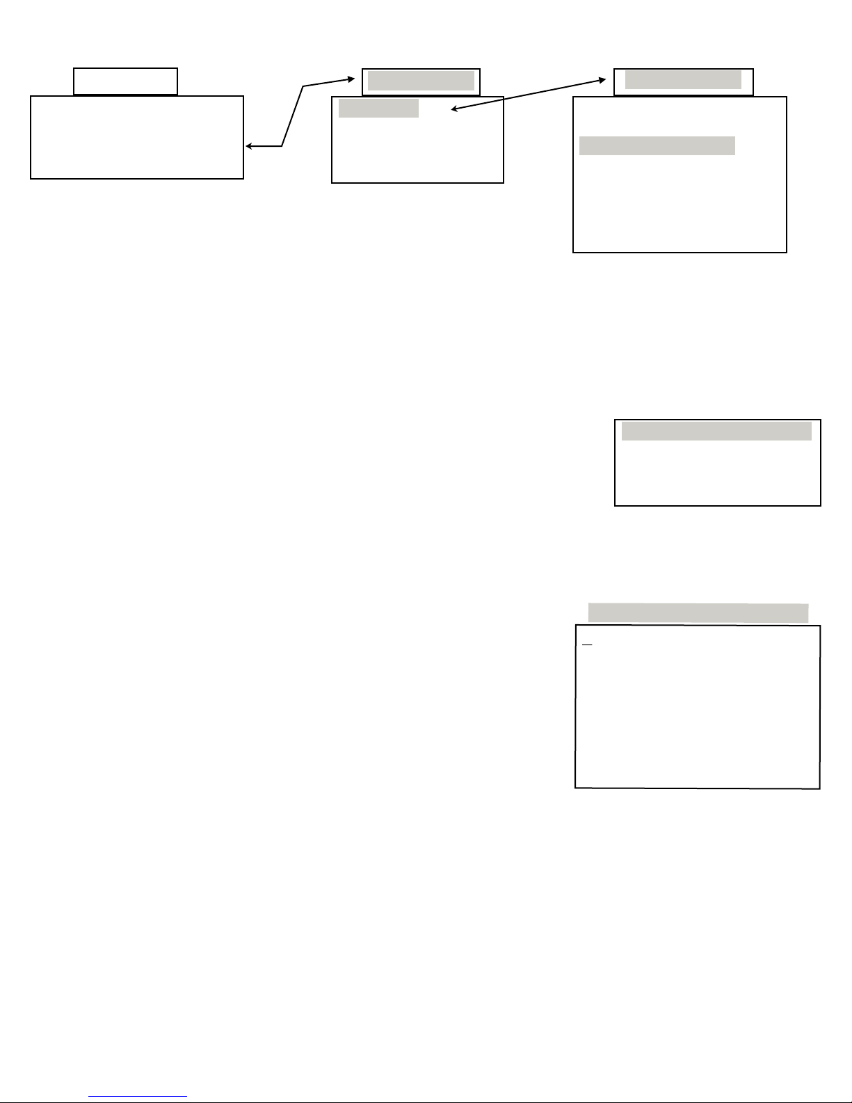
CHANGING RELAY TYPE
Main Menu
Service LAN
Data Security
Relays Relay Type
Advanced System
The two dry contact Auxiliary Relays per pool are a standard feature in PoolWarden. Please review this
section to understand how to configure the programming within PoolWarden to control many of the pools
additional equipment such as Heaters, Circulation Pumps, Water Levelers, Back Up Sanitizers, etc. Please
note that both Auxiliary Relays can also manage the same standard pH and ORP control types that the main
pH and ORP relays can manage. From the Main Menu select “Relay Type”, then select Pool1 or Pool2 and
scroll down and select the Aux1 or Aux2 which are the auxiliary relays for Pool1. If Pool2 is selected then
the Aux3 and Aux4 would be the auxiliary relays for Pool2. Once one of the Auxiliary Relays is selected the
following “Change Control Type” menu will appear.
⧫ Change: Press the Right Arrow “>” to scroll through the control types.
⧫ Save: Press the Left Arrow “<” to save the selection.
⧫ Back: Press the Back key to cancel out of this menu.
Pool Selection
Pool - 1
Update All Pool1
Pool - 2
Update All Pool2
PH1 Acid(pH-)
ORP1 Liquid (ORP+)
Aux1 Not Used
Aux2 Not Used
Alarm Not Used
Name:
Aux1 Name:
Aux2 Name:
Relay Selection
Change Control Type
< -save > -change
Back -cancel
> Not Used
Once saved the relay settings can be changed in the “Relay Setup” menu. Use the “Relay Type” menu to
set pH control from Acid to Base, to select the type of sanitizer that is being used or to select from a number
of choices for the AUX relays.
Heater Control Type
⧫ Manual Time 00:02:00: Is the amount of time you can set a relay to
turn on manually (Default Setting 2 Minutes). When you turn on the
relay manually in the service menu, the relay will be on for 2 minutes
in this case. To change the time press Enter and edit the time and
press Enter to save.
⧫ On If Temp < 0: This is the Main Temperature set-point and the
factory default setting is zero “0” or disabled. The relay will turn the
Heater on if the Temperature falls below the set point and will turn off
once the set point is achieved.
⧫ Night Temp < 0: This is the Secondary Temperature set-point and the factory default setting is zero “0”
or disabled. This secondary set point works in conjunction with the Advanced Menu. The relay will turn
the Heater on if the Night Temperature falls below the set point and will turn off once the set point is
achieved.
⧫ On Delay 00:01:00: The on delay, in this case 1:00 minute, is necessary to prevent the relay and hence
the heater from turning on and off frequently if the temperature fluctuates back and forth from from the
set-point. The relay will not turn on unless the setpoint condition is satisfied for at least 1:00 Minute - then
the relay will turn on for at least the programmed “On Time 00:02:00” in this case 2 minutes.
Aux1 Heater Relay Selected
ManualTime 00:02:00
On If Temp < 0
Night Temp < 0
On Delay 00:01:00
MinTimeOn 00:02:00
MinTimeOff 00:02:00
Off if Flow Off - 1
Overfeed 10:00:00
⧫ MinTimeOn 00:02:00: This is the total amount of time the relay will be ON if the Temperature dips
below the setpoint. The default setting is 2 Minutes. This command works in conjunction with the
MinTimeOff Command. This prevents the heater from kicking on and off frequently if the temperature is
fluctuating around the set-point.
PoolWarden Manual www.poolwardentraining.com 530-205-4520 33
Page 34

⧫ MinTimeOff 00:02:00: This is the total amount of time the relay will be OFF if the Temperature reaches
the set-point and the relay has been on at least the MinTimeOn. The default setting is 2 Minutes. This
command works in conjunction with the MinTimeOn Command above. This prevents the heater from
kicking on and off frequently if the temperature is fluctuating around the set-point. Never set this time to
00:00:00, that will keep the timers from properly resetting.
⧫ Off if Flow Off - 1: This Aux1 Relay will be turned off if “No Flow”
is detected in Flow Switch Input 1.
Pool1 uses Flow Switch Input 1 and Pool2 uses Flow Switch Input 3. Never allow the heater to turn on if
there is no flow. The heater will have it’s only flow detection which will also keep that from happening.
⧫ Overfeed 10:00:00: The Overfeed time represents the maximum amount of time a Heater can be on in
a 24-Hour period from midnight to midnight. Calculate the maximum amount of total time the heater
would be on in a 24-Hour period and enter the time here. The default time of 10:00:00 will most likely not
be correct. This will prevent the Heater from continuously running if something goes wrong with the
temperature sensor.
Feed Daily Control Type
Feed Daily can be used to turn on a piece of equipment at the same time every day of the week that or
specific days. It can be used to perform the following:
❑Turn on at a specific time and off at a specific time
❑Can be enabled for any or all days of the week
❑When it is on, it can also cycle on and off
❑Can be disabled based on a flow switch being off
⧫ Manual Time 00:02:00: The manual time for any relay can be set up
to 23:59:58.
⧫ Day Of Week smtwtfs: This is the ON Command for this control
type, if all letters for the days of the week are left lower case, the relay
will not turn on. To enable the relay to turn on select the Day of Week
Aux1 Feed Daily Selected
ManualTime 00:02:00
Day of Week smtWtfs
Off If Time < 10:00:00
Off If Time > 12:00:00
On Time 00:30:00
MinTimeOff 00:30:00
Off if Flow Off - 1
command and press Enter, then select numbers 1 through 7 representing Sunday through Saturday
and toggle between the lower case and uppercase letter of the week. Lower case is disabled and
uppercase means the relay will be enabled or turned on on that day of the week.
⧫ Off If Time < 00:00:00: This is a modifying command to the Day Of Week Setting and is where the relay
will be off if the time of day is less than the configured time setting. The default setting is zero “00:00:00”
or disabled. Enter the time based on 24-Hour Military Time and press Enter to save.
⧫ Off If Time > 00:00:00: This is a modifying command to the Day Of Week Setting and is where the relay
will be off if the time of day is greater than the configured time setting. The default setting is zero
“00:00:00” or disabled. Enter the time based on 24-Hour Military Time and press Enter to save.
⧫ On Time 00:00:00: This command is used to cycle the relay on and off continuously. Enter the desired
on time for the cycle (such as 2 Hours or 02:00:00) and press Enter to save the setting.
⧫ MinTimeOff 00:00:00: When the relay is going to cycle on and off during the on portion of the day this
command controls how long it will be off. Once this off time has been reached the relay will turn back on
for the On Time. If this cycling feature is going to be used do not leave either the On Time or the
MinTimeOff at 0, they are used together for proper operation.
⧫ Off if Flow Off - 1: The relay will be turned OFF if “No Flow” is detected in Flow Switch Input 1. Press
Enter to cycle between Flow Switch 1, 2, 3, 4 and none.
Example: The commands listed in the above box for this section will have Aux1 cycling on for 30 minutes,
and off for 30 minutes on Wednesday between 10AM and noon.
PoolWarden Manual www.poolwardentraining.com 530-205-4520 34
Page 35

Alarm Out Control Type
Alarm Out is where an external alarm can be connected to an Auxiliary Relay
and configured in this menu. This may be needed in cases where a more
pronounced sound or light is needed.
⧫ On if Alarm On - Yes: When set to Yes the Aux relay will be on if the alarm light is on.
⧫ Off if Flow Off - 1: The relay will be turned OFF if “No Flow” is detected in Flow Switch Input 1. Press
Enter to cycle between Flow Switch 1, 2, 3, 4 and none. If the circulation pump turns off at night you
may not want this additional alarm output to be on which can be detected by no flow.
On if Alarm On - Yes
Off if Flow Off - 1
Alarm Out
Superchlorination
Use this relay control type to feed an increased amount of sanitizer once
a week or a couple times a week. This relay control type is the same as
the Feed Daily and only the new additional commands are discussed
here.
⧫ Manual Time 00:02:00: The manual time can be used to test the
sanitizer feed for superchlorination to make sure it is connected
properly..
⧫ Day Of Week smtwtfs: Set the days of the week to perform
superchlorination.
⧫ Off If Time < 00:00:00: Set the time to start the superchlorination.
⧫ Off If Time > 00:00:00: Set the time to end the superchlorination.
⧫ On Time 00:00:00 and MinTimeOff 00:00:00: The mixing times may not be needed, but for a smaller
body of water you may want to feed sanitizer for 15 minutes and let it mix for another 15 with the relay
OFF to give the sanitizer time to mix.
⧫ Off If ORP>700: The setpoint for a superchlorination cycle is to turn off if the ORP is higher than an ORP
setpoint. The feed cycle will continue until enough sanitizer has been added to reach this setpoint of the
Off If Time value has been reached. If you are going to feed a set amount of chlorine based on time only
set this value to 0 to skip it.
⧫ Off If pH> 7.9: ORP is affected by pH and as the pH goes up the ORP value goes down. If when starting
the superchlorination cycle the acid storage tank is empty the pH may be at a higher then desired value
causing the ORP to be lower which could lead to feeding more sanitizer than desired. If you are going to
feed a set amount of chlorine based on time and not using the ORP setpoint then set this value to 0 to
skip it.
ManualTime 00:02:00
Day of Week smtwtfS
Off If Time < 22:00:00
Off If Time > 23:00:00
On Time 00:15:00
MinTimeOff 00:15:00
Off If ORP>700
Off If pH > 7.9
Off if Flow Off - 1
Superchlorination
⧫ Off if Flow Off - 1: The relay will be turned OFF if “No Flow” is detected in Flow Switch Input 1. Press
Enter to cycle between Flow Switch 1, 2, 3, 4 and none.
Water Level Control Type
Water Level is where an external pool water level feed can be connected to an Auxiliary Relay and
configured in this menu. If a water level switch is used it should be connected to Flow 2 for Pool1 and Flow 4
for Pool2. When the water is below the switch level then water should be added. The flow switch can be
either on when the water is low or off when the water is low depending on the type of switch, read the
following carefully to make sure you select the correct turn on condition.
⧫ Manual Time 00:02:00: Is the amount of time you can set a relay to turn on manually (Default Setting 2
Minutes). To change the time, enter the new time and press Enter to save.
⧫ On if Flow On - none: The Aux Water Level Relay will be turned on if “Flow” is detected in a Flow
Switch Input. Set this command to the appropriate flow switch input if the switch is ON when the water is
low. Note: If setting the On if Flow On to a switch value, leave On if Flow Off set to none.
⧫ On if Flow Off - none: The Aux Water Level Relay will be turned on if “Flow” is detected in a Flow
Switch Input. Set this command to the appropriate flow switch input if the switch is OFF when the water
is low. Note: If setting the On if Flow Off to a switch value, leave On if Flow On set to none.
PoolWarden Manual www.poolwardentraining.com 530-205-4520 35
Page 36
⧫ Off If Time < 00:00:00: This command will keep the relay off if the
time of day is less than the configured time setting. The default setting
is zero “00:00:00” or disabled. Enter the time based on 24-Hour
Military Time and press Enter to save. Leave this at 00:00:00 if it
doesn’t matter the time of day to add water.
ManualTime 00:02:00
On if Flow On -none
On if Flow Off-none
Aux1 Water Level
Off If Time < 00:00:00
⧫ Off If Time > 00:00:00: This command will keep the relay off if the
time of day is greater than the configured time setting. The default
setting is zero “00:00:00” or disabled. Enter the time based on 24-Hour
Military Time and press Enter to save. Leave this at 00:00:00 if it
Off If Time > 00:00:00
Off if Flow Off-none
Overfeed 00:00:00
doesn’t matter the time of day to add water.
⧫ Off if Flow Off - none: The Aux Water Level Relay will be turned off if “No Flow” is detected in the Flow
Switch Input indicated.
⧫ Overfeed 00:00:00: The Overfeed time represents the maximum amount of time a Water Leveler can
be on in a 24-Hour period from midnight to midnight. Calculate the maximum amount of total time the
Water Leveler would be on in a 24-Hour period and enter the time here. The default time of 00:00:00 or
disabled. This will prevent the possible overflow situations.
Time Based Water Level: If not using the flow input for water level but a time base such as 15 minutes a
day, then set the On if Flow On - 1 or 3 to use the flow switch in the flow cell which will turn this relay on, and
then use the time of day commands to set the amount of minutes to add water per day. You could also use
the Feed Daily relay control type for more control such as selecting the days of the week to add water.
ORP Control Types
There are 4 control type selections for ORP: Liquid, Feeder, Cal Hypo and Salt System. Liquid and Cal
Hypo have the exact same relay programming, and Feeder and Salt System have the exact same relay
programming.
Proportional and ORP Over Run: For a feeder, proportional control isn’t needed because the relay will
stay on until the setpoint is achieved. ORP Over Run allows for 0, 5, 10 or 15mv to be added to the setpoint,
it will turn on at the setpoint, and off at the setpoint plus this value.
Liquid and Cal Hypo Feeder and Salt System
ManualTime Same
Proportional ORP Over Run
On If ORP<700 Same
On Delay Same
On Time MinTime On
MinTimeOff Same
Off If pH Same
Off if RLY On Same
Off if Flow Off Same
SetOvrfeed Same
Manual feed time
ORP Setpoint
Turn on delay
When turning off, stay off at least this long
PH Lockout
Keep off if currently in a pH feed cycle
Only allow feeding if there is flow
Feed limit based on the setpoint being achieved
Overfeed Same
Daily feed limit
On Time and MinTimeOn: For liquid, the On Time is part of the cycle, it will be on for the programmed On
Time or less and then the MinTimeOff will start which allows the added chemicals to mix. For the Feeder,
the MinTime On is the minimum amount of time the relay will be on, even if the setpoint is achieved. Note
that the relay may be on longer than this time if the setpoint isn’t achieved within the programmed time.
PoolWarden Manual www.poolwardentraining.com 530-205-4520 36
Page 37
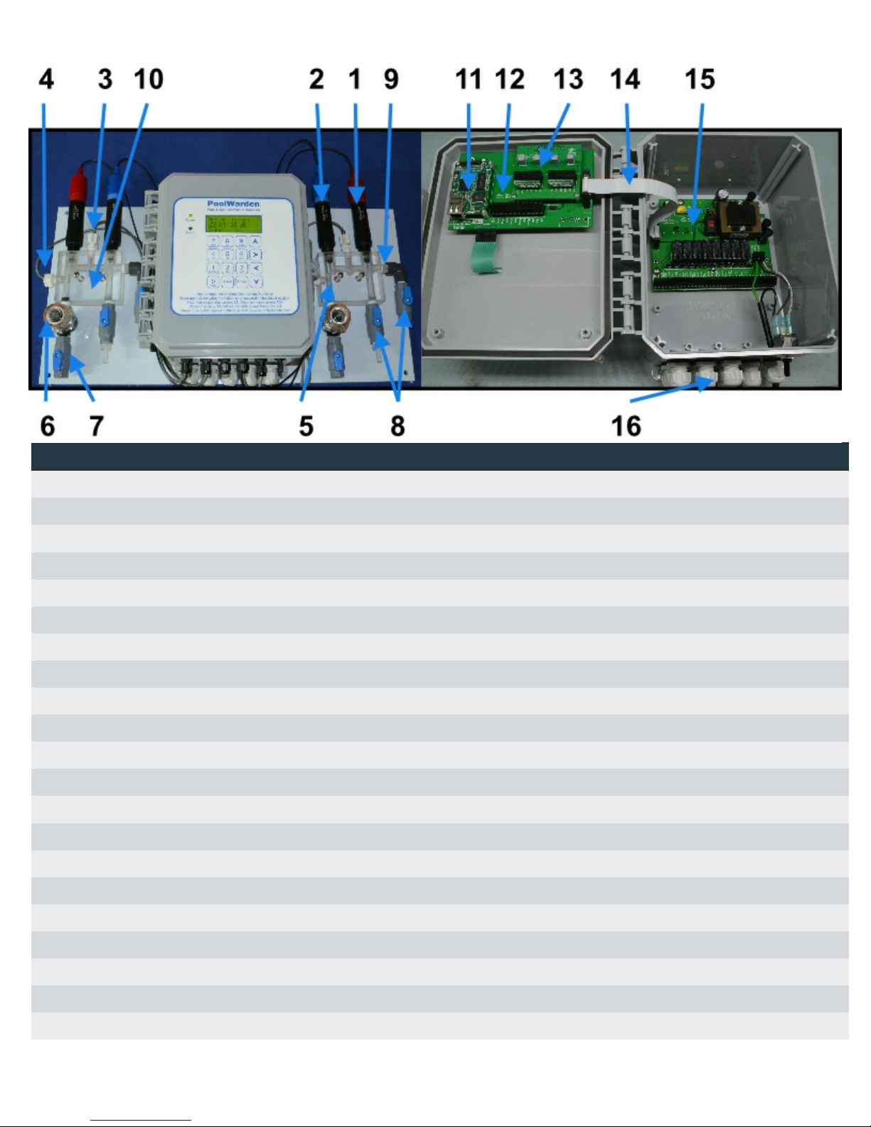
Replacement Parts
Item Part Number Type Description
1 ORP-COMP Sensor ORP Sensor, platinum band, red sensor body
1 ORP-COMG Sensor ORP Sensor, gold disk for salt water chlorinators
2 PH-COM1 Sensor PH Sensor, blue sensor body
3 PW-T10K-3ft Sensor Temperature sensor, 3 foot cable
4 PW-Flow3 Sensor Flow sensor detector, 3 foot cable
5 PW-FlowCell-MAG Sensor Flow sensor magnet
6 PW-Strainer Flow Cell Inlet water strainer with stainless steel screen
6 PW-Strainer-Screen Flow Cell Stainless steel screen for inlet water strainer
7 1250-070-01 Flow Cell 1/4" FNPTxFNTP, SMC 2-Way Ball Valves
8 1250-080-01 Flow Cell 1/4" Ball Valve FNPT x MNPT, SMC
9 1250-100-01 Flow Cell 1/4" NPT, PP Threaded Nipple
10 2070-010-01 Flow Cell Machined PoolWarden flow cell acrylic block
11 PWLANC Circuit Board Ethernet communication module
12 2370-020-07 Circuit Board PoolWarden motherboard
13 2370-130-06 Circuit Board PoolWarden sensor card dual pool
13 2370-050-06 Circuit Board PoolWarden sensor card single pool
14 2570-080-01 Cable Motherboard to relay board interconnect cable
15 2370-120-10 Circuit Board PoolWarden dual pool relay board (8 relays)
15 2370-040-10 Circuit Board PoolWarden single pool relay board (4 relays)
16 1020-080-01 Cable Cable grip, 1/2" NPT (.23-.47"), GRAY, bottom row
16 1020-070-01 Cable Cable grip, 3/8" NPT (.20-.39"), GRAY, top row
PoolWarden Manual www.poolwardentraining.com 530-205-4520 37
Page 38

Maintenance
PoolWarden Enclosure
The enclosure can be cleaned with a soft cloth that is moist with water. Take extra care when cleaning the
clear display window. To clean the display window make sure the cloth hasn’t been used to clean anything
else or it may have grit which may scratch the clear screen.
The PoolWarden includes cable grips on the bottom side of the box. If any are not used make sure to fill
them so that the opening is closed. If a cable grip is left open bugs may enter the inside and leave droppings
and nests which should be removed.
Sensor Maintenance
The sensors must be clean to operate properly. The strainer in front of the flow cell will catch most debris
but oils and chemical deposits will get through. Slow response, increased need to calibrate and inconsistent
readings are indicators that the sensors need to be cleaned or replaced.
To clean the sensors, turn off both valves to the flow cell and carefully remove the pH and ORP sensors
from the flow cell. The small white dots on the bottom of the sensor should be flush with the black sensor
body and clearly visible. Use a soft brush and a mild detergent to remove any oil and contamination from the
glass bulb and the small white dots. Do not let the sensors dry out as that may damage the sensor, after
cleaning apply Teflon tape to the threads and reinstall the sensors.
ORP and pH Sensor Replacement
The PoolWarden ORP and pH sensors have a warranty to last at least 1 year and will most likely last from
1.5 to 3 years or longer. An indication that it is time to replace a sensor is the percentage listed on the
calibration screen in the PoolWarden service menu. If the percentage is 99% then the sensor is not able to
be properly calibrated and should be replaced. There is a date code on the sensor body that can also aid in
determining if the sensor needs to be replaced. If one sensor needs to be replaced and both the ORP and
pH sensor have the same date code it is recommended to replace them both.
Part Number Type Description
ORP-COMP Sensor ORP Sensor, platinum band, red sensor body
ORP-COMG Sensor ORP Sensor, gold disk for salt water chlorinators
PH-COM1 Sensor PH Sensor, blue sensor body
Sensor Storage
During the installation of the PoolWarden make sure to the sensor caps. To store the sensors turn off both
valves to the flow cell and remove the sensors. Add a little water to the sensor cap and hand tighten the
sensor to the cap. The cap should have a small sponge that only needs to be moistened.
Cold Temperatures
The ORP and pH sensors should not be exposed to freezing conditions. If the outside temperature is below
freezing this may damage the sensors and they should be removed to protect them. Always store them with
their protective caps.
Always drain the water from the flow cell, strainer and tubing to to flow cell to prevent damage in freezing
conditions.
PoolWarden Manual www.poolwardentraining.com 530-205-4520 38
Page 39

Troubleshooting
Flow not registering even though the magnet is up
⧫ Make sure the flow sensor detector wire is connected to the correct switch input. Pool 1 uses Flow 1 and
Pool 2 uses Flow 3. On the readings display, the flow indication for Pool 1 is Flow input 1 and for Pool 2
is Flow input 3, this can’t be changed. If you moved the Pool 1 flow sensor to Flow input 2 the display will
still show the status of Flow input 1.
⧫ Rotate the flow sensor ¼ turn. There is a polarity between the magnet and the flow sensor and rotating
the sensor slightly may help.
Alarm light is on, but the readings are OK
⧫ There are many factors that affect the alarm status. From the readings screen press the right arrow to
enter the alarm conditions screen. This will list all of the factors from the alarm settings that are causing
the alarm light to be on.
ORP and pH readings are way off
⧫ If the ORP and pH sensors wires are swapped this will cause readings that are way off. The ORP sensor
will read near 0 and the pH sensor will be maxed out. Check the wire connections.
⧫ Check the circuit boards and make sure they are all properly seated in their connectors.
⧫ Clean the sensors and check the date code.
ORP and pH readings are drifting
⧫ The most common cause of sensor drifting is a poor earth ground connection to the PoolWarden. A good
way to test the earth ground connection is to measure with a digital voltmeter one of the ground terminals
on the main board in the lid to a piece of metal in the pump room.
Chemical feeders are not turning on
⧫ The first test is to make sure they can turn on. Go to the service menu and select Manual Relay Mode
and turn on the feeder to test. If if doesn’t turn on then there may be a problem with the feeder, the wiring
or even the relay.
⧫ Try plugging the feeder into an alternate power source to make sure it can turn on.
⧫ The setting for the relay control require a flow switch to be on and an overfeed timer to not be reached.
ORP varies from day to night with the same pH and free chlorine
The presence of cyanuric acid in pool water is a challenge for ORP sensors as they detect the waters ability
to oxidize which cyanuric acid has an impact on and is dependant on the amount of sunlight hitting the
water. The PoolWarden has an advanced feature allowing for an automatic decrease in the ORP value at
night to help compensate for this effect (go to the advanced menu for more information). If there is cyanuric
acid in the water then the following guidelines may help:
⧫ Only calibrate the ORP sensor at the brightest time of the day. If you calibrate the sensor at night when
the chlorine is all available that will then lead to an overfeed condition on the next day when the sun is
out and the ORP drops.
Forgot Your Password
If you enabled the security feature and forgot your password all is not lost. Contact ControlOMatic with the
serial number and proof of ownership and a password reset code will be provided that will clear all of the
security passwords. Each PoolWarden has it’s own unique reset code and one that works on one
PoolWarden will not work on another.
PoolWarden Manual www.poolwardentraining.com 530-205-4520 39
Page 40

Technical Support
Please contact ControlOMatic at 530-762-1627 for sales and support. Send support emails to
[email protected]. The dedicated PoolWarden website with videos, tips, documents and more is:
www.poolwardentraining.com
Change List
The Poolwarden software is periodically updated with new features and bug fixes. This section lists by date
code which can be found on the last line of the opening screen any updated made in the specific version.
03/04/2016
⧫ Added support for a serial printer.
⧫ Ability to download the internally recorded data using a web browser.
⧫ When manual measurements are entered or the PoolWarden is calibrated, this data is sent to the server
with a timestamp.
⧫ Recording of the last 7 daily noontime readings.
⧫ Support for the White and Blue overlays.
⧫ Added quick jump to allow calibration without entering a password.
03/24/2015:
⧫ Added mv to the main reading screen for the units on the ORP sensor.
⧫ For control of pH and ORP, the flow sensor selection can’t be changed or set to none to disable flow
detection when feeding chemicals. This applies to the pH and ORP relays, not the AUX relays.
⧫ For control of pH and ORP, the overfeed timers can’t be set to 00:00:00 which would disable the
overfeed timers, the minimum value is now 00:01:00. This applies to the pH and ORP relays, not the
AUX relays.
⧫ Changed the PW-Free text to TrueDPD to reflect the new name. Changed the measurement cycle
choices from 5, 10, 15, and 30 minutes to 10, 20, 30 and 60 minutes.
⧫ Added Superchlorination as a relay control type.
PoolWarden Manual www.poolwardentraining.com 530-205-4520 40
Page 41

LIMITED WARRANTY
Models: This warranty applies to PoolWarden referenced here as “Controller”.
ControlOMatic, Inc. Warrants the controller to to be free from defects in manufacturing and
workmanship for a period of Five (5) Years from the date of manufacture for the electronic
main circuit board. All sensors and flow cells have a One (1) Year warranty. All other
supporting equipment to the controller are individually covered by the specific equipment
manufacturers warranty. Liability under this warranty is limited to the repair or replacement
of any device or component which is returned to ControlOMatic within the warranty period
by the original purchaser and found to be defective upon examination.
This warranty does not cover: (a) the purchaser’s labor or any servicing fees related to
replacement of the defective product; (b) damage resulting from the use of this product in a
manner inconsistent with normal use and the owners manual; ( c) damage as a result of
misuse, accident or neglect; (d) damage from improper testing, operation, or installation; (e)
damage resulting from not operating the controller on a dedicated circuit or under
conditions other than those recommended or at voltages or amperages other than those
indicated on the controller and in the owners manual; (f) acts of mother nature (lightning,
floods, earthquakes, etc); (g) modification of the controller in any way.
Defective parts should be returned to the local ControlOMatic Dealer. Any parts returned
directly to ControlOMatic require a Return Material Authorization (RMA) code issued by a
ControlOMatic Technician.
ControlOMatic makes no warranties, either expressed or implied, other than those stated
above. No representative has the authority to change or modify this warranty in any way.
Warranty Registration can be done at www.miniwarden.com or call 530-205-4520.
Any warranty claims should be directed to the following address:
ControlOMatic, Inc.
12659 Arbor ln
Grass Valley, CA 95949
530-205-4520
PoolWarden Manual www.poolwardentraining.com 530-205-4520 41
 Loading...