

Page 1
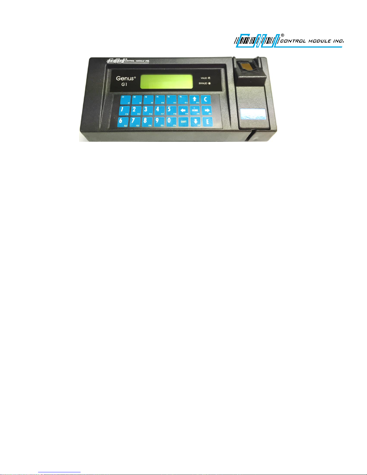
Genus® G1
MARK II
Users Manual
UM3010-2
November 2017
Revision C
Page 2

Genus G1 MARK II User Manual
UM3010-2
Contents
Introduction ................................................................................................................................................................8
Genus G1 Terminals ...................................................................................................................................................9
The User Interface ..................................................................................................................................................9
Terminal Features ................................................................................................................................................ 10
Terminal Specifications ....................................................................................................................................... 11
File System Specification ................................................................................................................................. 12
Relay Configuration ......................................................................................................................................... 12
Terminal Connections .......................................................................................................................................... 13
Module Options ................................................................................................................................................... 15
Installation ............................................................................................................................................................... 16
Power-Up ................................................................................................................................................................. 17
Online Mode ............................................................................................................................................................ 17
Offline Mode ........................................................................................................................................................... 18
Entering Offline ................................................................................................................................................... 18
Terminal Info Prompt .......................................................................................................................................... 18
Offline Setup Mode Menu Options ..................................................................................................................... 19
Offline Mode – User Operational Displays .............................................................................................................. 21
TERMINAL INFO ................................................................................................................................................... 21
CLEAR RAM .......................................................................................................................................................... 22
CLEAR FLASH ........................................................................................................................................................ 23
NETWORK SETUP ................................................................................................................................................. 24
ENABLE DHCP .................................................................................................................................................. 24
TERMINAL IP .................................................................................................................................................... 24
SUBNET MASK ................................................................................................................................................. 24
GATEWAY IP..................................................................................................................................................... 25
PRIMARY DNS .................................................................................................................................................. 25
SECONDARY DNS ............................................................................................................................................. 25
ENABLE TELNET ............................................................................................................................................... 25
TELNET PORT ................................................................................................................................................... 26
TELNET PIN ...................................................................................................................................................... 26
ENABLE TFTP .................................................................................................................................................... 26
SAVE CHANGES ................................................................................................................................................ 26
WIFI NETWORK SETUP ......................................................................................................................................... 27
Revision C November 2016 2
Page 3

Genus G1 MARK II User Manual
UM3010-2
WIFI NETWORK INFO ....................................................................................................................................... 27
QUICK CHECK ....................................................................................................................................................... 27
COMM TEST ......................................................................................................................................................... 28
READER SETUP ..................................................................................................................................................... 28
Biometric Reader ............................................................................................................................................. 29
SETUP PIN ............................................................................................................................................................ 30
DAIL-UP NETWORK .............................................................................................................................................. 30
SETUP TIME ZONE ............................................................................................................................................... 31
WEB SETUP .......................................................................................................................................................... 31
EXIT SETUP ........................................................................................................................................................... 32
Genus WiFi ............................................................................................................................................................... 33
Genus WiFi Configuration/Setup ......................................................................................................................... 34
WiFi Module .................................................................................................................................................... 34
IP Addresses..................................................................................................................................................... 34
WiFi Module - Fallback .................................................................................................................................... 34
Genus Terminal................................................................................................................................................ 34
DHCP and WiFi Module setup ......................................................................................................................... 34
SETTING UP WIFI ................................................................................................................................................. 35
WiFi Module Fallback Settings......................................................................................................................... 35
WiFi Module Fallback LED Indication .............................................................................................................. 35
WiFi Module Security Settings......................................................................................................................... 36
Web Browser Interface ........................................................................................................................................... 37
Logon ................................................................................................................................................................... 37
Home page – Genus Administration ................................................................................................................... 38
Current Time .................................................................................................................................................... 38
Time Zone ........................................................................................................................................................ 39
Total RAM ........................................................................................................................................................ 39
File Versions and Fields ................................................................................................................................... 39
Web Server Configuration ............................................................................................................................... 39
User Name and Password................................................................................................................................ 39
Port .................................................................................................................................................................. 39
Save Settings Button ........................................................................................................................................ 39
Reset Terminal ................................................................................................................................................. 39
Logout .............................................................................................................................................................. 39
Revision C November 2016 3
Page 4

Genus G1 MARK II User Manual
UM3010-2
Network setup ......................................................................................................................................................... 40
Web Service Setup ................................................................................................................................................... 41
Enable Web Service ............................................................................................................................................. 42
Discovery URL ...................................................................................................................................................... 42
Bulk Transaction Count ....................................................................................................................................... 42
Data Maintenance ............................................................................................................................................... 43
RMS Table Listing ............................................................................................................................................. 43
Clear Flash ....................................................................................................................................................... 43
Clear RAM ........................................................................................................................................................ 44
Directory Listing ............................................................................................................................................... 44
Thread Listing ...................................................................................................................................................... 45
Application Log .................................................................................................................................................... 45
Transaction Log ................................................................................................................................................... 46
Debugging ............................................................................................................................................................ 47
Debug Level ..................................................................................................................................................... 47
Maximum Debug Time .................................................................................................................................... 47
Maximum Debug Storage ................................................................................................................................ 48
Storage Limit Action ........................................................................................................................................ 48
Troubleshooting Terminal Issues ............................................................................................................................ 49
Reference ................................................................................................................................................................ 53
Steps to Re-Program Genus Firmware: ............................................................................................................... 53
Genus (“System”) file update: ......................................................................................................................... 53
Classes (API) update: ....................................................................................................................................... 53
Confirming Updates: ........................................................................................................................................ 53
Loading A Customer Defined Java Application .................................................................................................... 54
Loader Mode ....................................................................................................................................................... 54
Calculating Number of Transactions That Can Be Stored ................................................................................... 55
Telnet Session ...................................................................................................................................................... 56
Programming Table (Code 39) ............................................................................................................................. 57
Service & Technical Support .................................................................................................................................... 60
RMA Policy ........................................................................................................................................................... 60
Technical Support ................................................................................................................................................ 60
Standard Terms and Conditions of Sale .............................................................................................................. 60
Revision C November 2016 4
Page 5

Genus G1 MARK II User Manual
Warnings
Voltage: The lightning flash with arrowhead symbol, within a triangle, is intended to alert the
user to the presence of dangerous voltage within the inside of the product that may be
sufficient level to constitute a risk of electric shock to persons.
Instruction: The exclamation point, within a triangle, is intended to alert the user to the
presence of important operating and servicing instructions in the literature accompanying the
Terminal.
Disclaimer
No part of this publication may be reproduced, or transmitted in any form or by any means
without the written permission of Control Module, Inc. The information described by this
publication is specifically intended for use by customers and resellers of Control Module
Data Collection products and data collection systems and only for use with Control Module
Data Collection products and data collection systems.
UM3010-2
© Control Module, Inc. 2017. All Rights Reserved.
Genus® is a registered trademark of Control Module, Inc. Other brands and names
contained in this document are the property of their respective owners.
The information in this manual is subject to change without notice and does not represent a
commitment on the part on Control Module, Inc.
Revision C November 2016 5
Page 6

Declarations
Control Module, Inc.
Model: Genus® 3010-2
Emissions Requirements:
EN 55022:1998 Class A, Conducted Emissions, 150 kHz to 30 MHz
EN 55022:1998 Class A, Radiated Emissions, 30 MHz to 1 GHz
EN 61000-3-2:2000 Harmonic Current Emissions
EN 61000-3-3:1995 Voltage Fluctuations and Flicker
Genus G1 MARK II User Manual
UM3010-2
Immunity Requirements:
EN 61000-4-2:1995 Electrostatic Discharge, 8kV Direct Air, 4kV Direct and Indirect
Contact
EN 61000-4-3:1996 Radiated RF Immunity, 80MHz-1000MHz, 3V/m, 80% AM 1kHz
EN 61000-4-4:1995 EFT, 1kV Power, 0.5kV I/O
EN 61000-4-6:1996 Surge Immunity, 1kV Differential Mode
EN 61000-4-6:1996 Conducted RF Immunity, 150kHz-80MHz, 3Vrms, 80% AM 1kHz
EN 61000-4-11:1994 Voltage Dips and Interruptions
Applicable EC Directive(s):
Applicable Harmonized
Standards:
Safety: EN 60950
EMC: EN61000-6-4, EN55011, EN61000-6-2, EN61000-4-2, EN61000-4-4,
EN61000-4-5, EN61000-4-6, EN61000-4-11
EC Low Voltage Directive 73/23/EEC
EC EMC Directive 89/336/EEC
FCC Compliance
The Control Module Model 2015 Time and Attendance Terminal conforms to the requirements of
FCC PART 15, SUBPART B, CLASS A.
Para. 15.107(b) for Conducted Emissions, 150 kHz to 30 MHz
Para. 15.109(b) for Radiated Emissions, 30 MHz to 1 GHz
Revision C November 2016 6
Page 7

Genus G1 MARK II User Manual
UM3010-2
Note: This equipment has been tested and found to comply with the limits for a Class A digital device, pursuant
to part 15 of the FCC Rules. These limits are designed to provide reasonable protection against harmful
interference when the equipment is operated in a commercial environment. This equipment generates,
uses, and can radiate radio frequency energy and, if not installed and used in accordance with the
instruction manual, may cause harmful interference to radio communications. Operation of this
equipment in a residential area is likely to cause harmful interference to radio communications. Operation
of this equipment in a residential area is likely to cause harmful interference in which case the user will be
required to correct the interference at his own expense.
Revision C November 2016 7
Page 8

Genus G1 MARK II User Manual
UM3010-2
Introduction
Welcome to Control Module’s Genus® G1 MARK II Data Collection Terminal.
The “Genius of Genus” is that it offers an intelligent Java programming language and enables companies – for
the first time – to realize the maximum potential of their workforce management terminals, by using them as a
powerful interface to connect highly customized applications and the databases that fuel them. The Genus open
and modular platform is designed to provide fast, accurate, and reliable data collection for any industrial
application. The Genus Terminal is ideal for time and attendance, workforce management, employee selfservice, shop floor data collection, and access control. Genus is the intelligent and affordable decision for any
organization.
Revision C November 2016 8
Page 9
Genus G1 MARK II User Manual
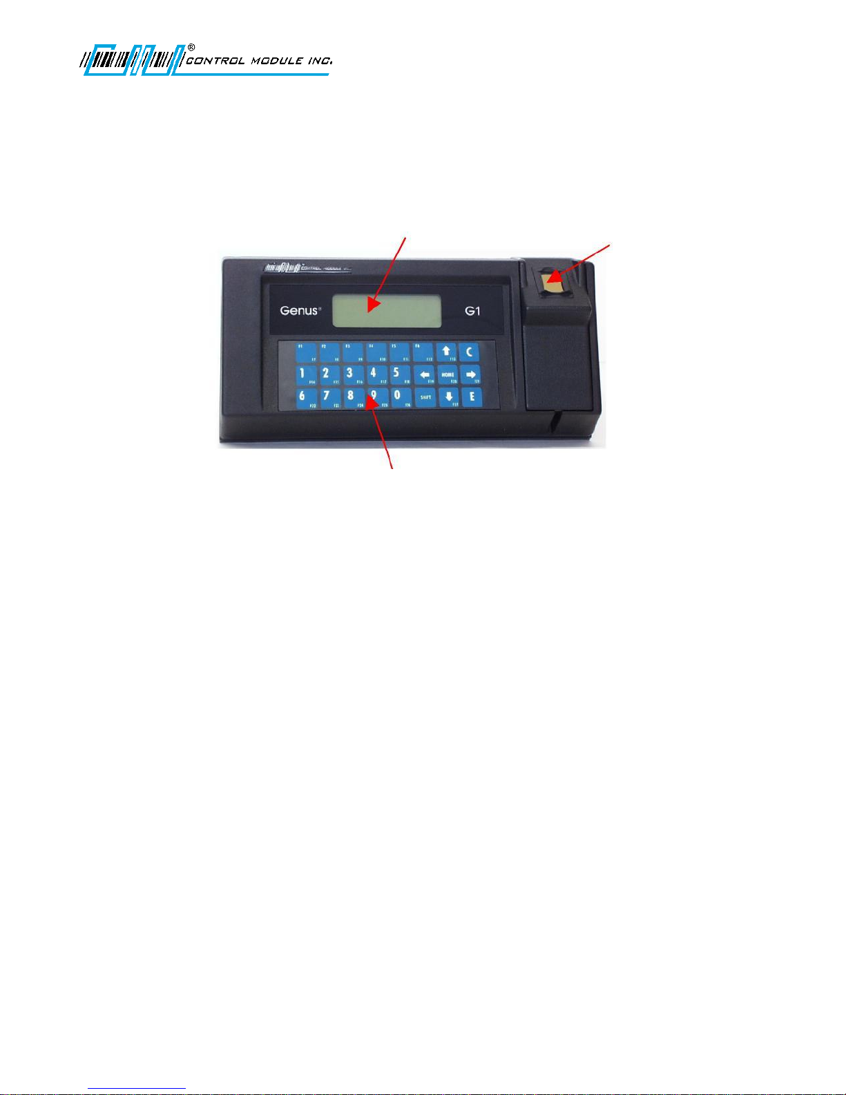
4X20 Character
Backlit LCD
Display
Optional Readers
Include:
Biometric
Barcode
Mag Track 1
Mag Track 2
Proximity
Smart card
UM3010-2
Genus G1 Terminals
Terminal features are labeled in the pictures below for reference. Explanations of terminal features, user
interface, hardware specifications and connections follow. All items discussed in this user manual apply to both
types of Genus G1 or Hardened Terminals.
3X8
Membrane
Keypad
The User Interface
The user interface offers options for data entry into the Genus G1 MARK II Terminal through the keypad and/or
internal or external card readers. User output is via a 4 line by 20 character backlit LCD display. The terminal also
has the capability to produce multiple sound tones to help guide the user.
The Genus G1 MARK II Terminal offers provisions for additional display control aside from the ability to write to
and clear the entire display. These include the ability to clear a single display line, position the cursor, and select
the cursor type (invisible, block, underscore, or blinking underscore).
A Web Browser Interface is integrated with the Genus G1 Mark II Terminal to allow changes to configuration
files, data viewing and development interface updates. Some items overlap between the Offline setup and the
Web Browser Interface.
Revision C November 2016 9
Page 10

Genus G1 MARK II User Manual
UM3010-2
Terminal Features
Memory Configuration The terminal is equipped with 32 Mb of dynamic memory, 2 Mb of non-volatile memory
for data retention, and 40 Mb of Flash memory for program storage, and user defined long term storage.
Programmability The terminal is designed to be a Java-capable embedded data collection platform. Users may
create, load, and execute Personal Java compliant applications that utilize existing OEM classes for display,
keyboard, biometric, barcode, magnetic, proximity, smartcard (Mifare®, iClass®), and Digital inputs and outputs
(DI/DO). A software development kit (SDK) is available separately that provides development documentation,
development support, and samples for the use of the OEM classes.
Data I/O The terminal provides for program control for three digital inputs, and Wiegand Data0/Data1 input or
output signals. A relay port is also provided for external low voltage devices.
Host Interface The terminal comes with a dedicated Ethernet port for connection to 10/100 Ethernet networks.
DHCP or static IP address configuration is supported.
Display The terminal is equipped with a 4 line by 20 character liquid crystal display (LCD) The full alphanumeric
character set is supported. LED backlighting provides viewing in low light conditions. The display has a CMI
standard lens.
Keypad The terminal is equipped with a 3 x 8 membrane keypad, with three horizontal rows of eight keys each.
The terminal is available with a CMI Standard Overlay, or a custom overlay created per customer requirements.
Power The configuration uses a +18 VDC .8 amp power pack to power the terminal. The power pack is UL listed
and CSA certified.
Audio Annunciator This is programmable with variable tone and duration capability.
Revision C November 2016 10
Page 11

Terminal Specifications
Keypad - with local buffering
10 Numeric Keys (0 through 9)
Function keys alternately can produce
punctuation symbols.
Clear and Enter Keys
Home, Up, Down, Left, and Right arrow direction
keys
Shift key
All keys are programmable
Display
4 Line by 20 Character Backlit LCD Display
Media Readers - 2 Internal reader ports, 1 External
reader port, 1 Barcode wand port
Magnetic Track 1 and 2
Barcode Code 39 and code 39 full ASCII,
Interleaved 2of5, Code 128
Proximity allows up to a 99 bit badge (HID,
MOTOROLA)
Smartcard (Mif are®, iClass®)
Biometrics (Fingerprint)
Beeper
Variable duration monotone
beep Variable duration warble
beep Emit a series of beeps
Host Interface
RS232, RS485
10/100 Ethernet
Modem option via serial port (PPP)
WiFi option
External Control
Relay Output—30VDC @ 1A
LED
Two Status LEDs – Valid (green), Invalid (red)
Power Requirements
15 -20 VDC
Environment
Operating 0°to 50°C (32° to 122°F)
Storage -20° to 70°C (-4° to 158°F)
Humidity 0 to 90 % non-condensing
Genus G1 MARK II User Manual
UM3010-2
Revision C November 2016 11
Page 12
Genus G1 MARK II User Manual
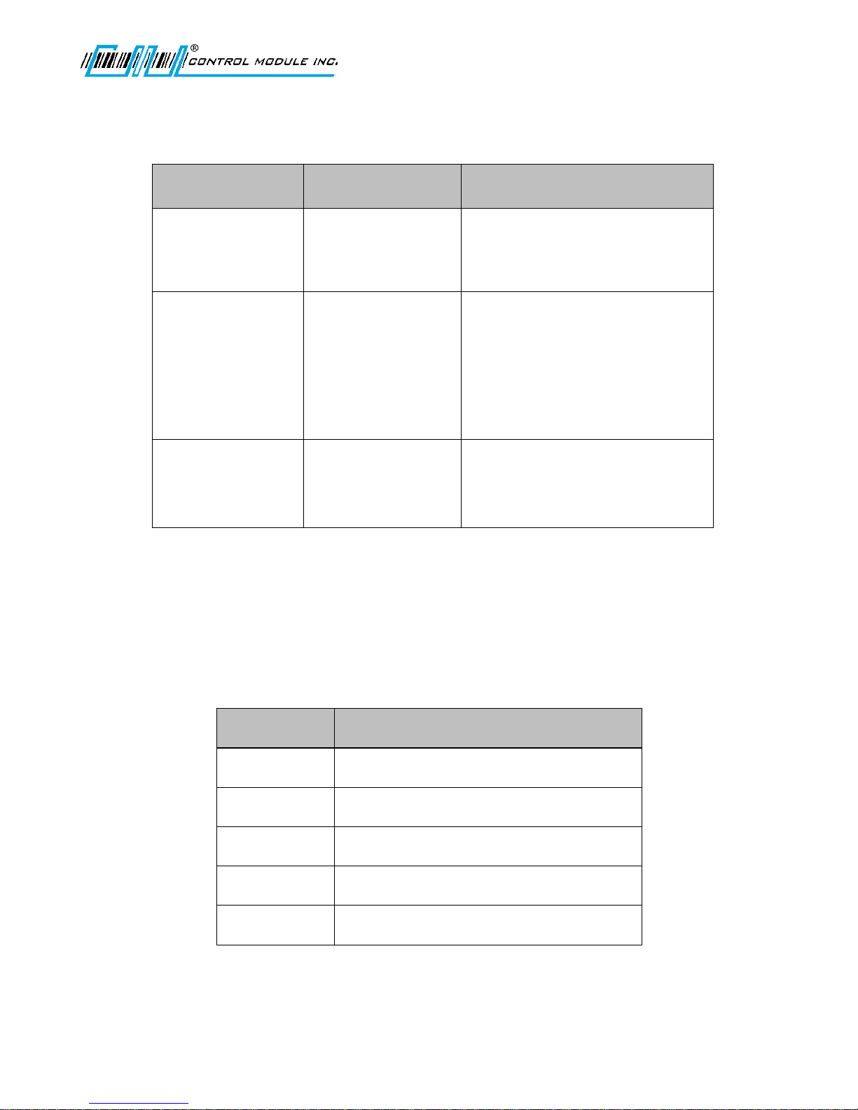
Storage Device
Memory Size
Location
‘\flashdisk’
40 Mbytes
Seldom write, frequent read. Used
for firmware, user applications, and
application data.
‘\ramdisk’
2 Mbytes
High read/write usage. Data is
preserved through power loss. Often
used for transaction (punch) storage.
1MB of storage available. Refer to
Calculating Number of Transactions
That Can Be Stored in the Reference
chapter.
‘\scratchdisk’
5 Mbytes
High read/write usage. Temporary
file storage. Not preserved through
power outage.
Relay Port
Internal Power Function
1
Normally open contact
2
Common contact
3
Normally closed contact
4
Ground
5
+18 VDC
UM3010-2
File System Specification
The terminal provides file systems on different hardware devices. Instead of using the common alphabet
notation for file system devices ( ‘A:’, ‘C:’ ), the Genus terminal identifies the file storage devices as:
Relay Configuration
The relay port brings out the three relay connections at (common, normally open, normally closed) +18 VDC,
and ground. The common can optionally be connected to Pin 5 to provide an on board voltage source. The
current draw should not exceed 100mA. This +18 VDC source is useful when driving external buzzers, lamps, or
other low current, low voltage devices or a larger external relay, since it requires no external power source.
The Relay Output configuration supports both sourcing and non-sourcing. The Relay is a Form C contact relay
rated for 1 amp @ 30V AC/DC.
Revision C November 2016 12
Page 13
Terminal Connections
Ethernet Port
The Ethernet port supports the 10/100BASE-T network
connections. The Ethernet port is located on the backplate of
the Terminal and connects directly to CAT-5 cable.
No te : Po we r is no t av a i la bl e fr o m th e Et he rn et
po rt w it ho ut t he j um pe re d co nn ec to r on
th e Pe ri ph er al P ow er P or t .
Connector: 8-position RJ45.
Pinouts:
1 = Receive + 5 = +Vnet
2 = Receive – 6 = Transmit –
3 = Transmit + 7 = -Vnet
4 = +Vnet 8 = -Vnet
Serial Aux Port
The Serial Aux port provides a serial connection to interface
to serial peripheral devices or for modem communications.
Connector: 8 position RJ45.
Pinouts:
1 = DCD 5 = GND
2 = RXD 6 = +18 VDC (opt.DSR)
3 = TXD 7 = RTS
4 = DTR 8 = CTS
Scanner Port
The Scanner port provides CMI standard pinouts with the RJ11
connector.
Connector: 6 position RJ11
Pinouts:
1 = Wiegand Data 0 4 = Wiegand Data 1
2 = Ground 5 = Data
3 = +5 VDC 6 = +18 VDC
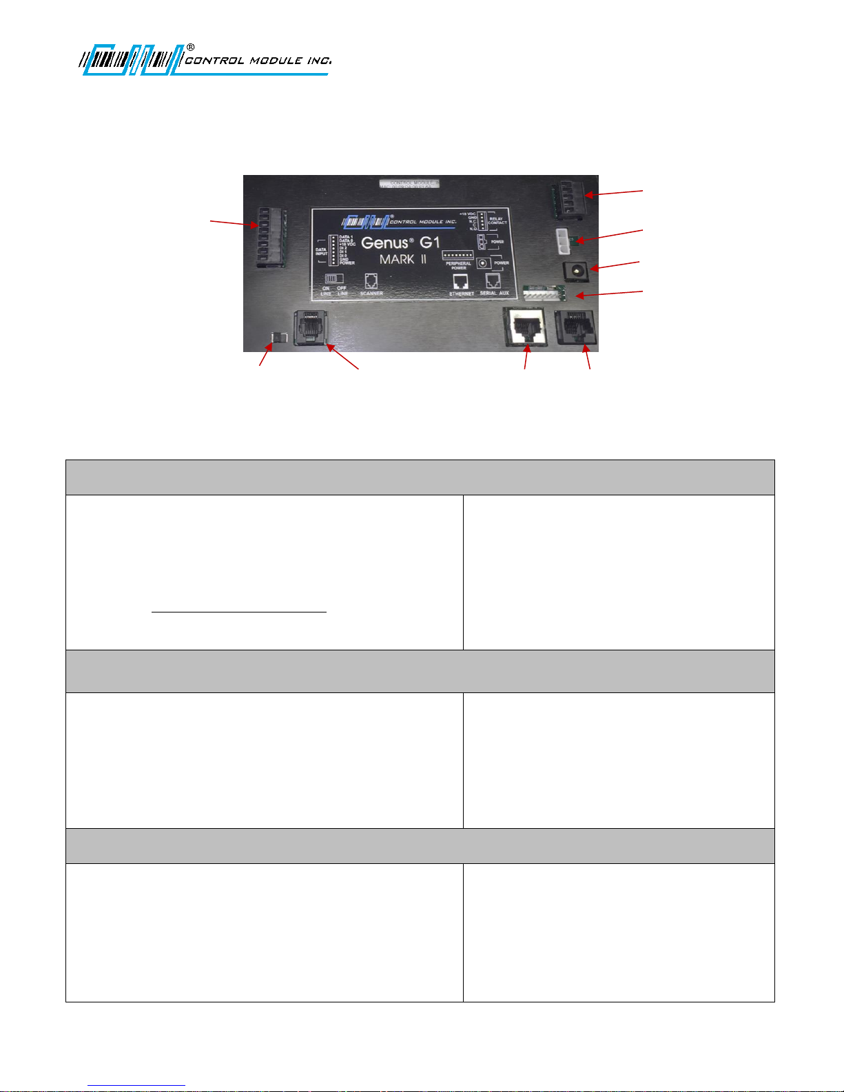
Data Input
Scanner Connection
Ethernet Port
Serial Aux Port
Power Port
Power Input
Peripheral Power Port
Relay Contact
Online/Offline
Terminal connections apply to both Genus G1 and G1 Hardened Terminals.
NOTE: All available options are shown, some models may differ.
Genus G1 MARK II User Manual
UM3010-2
Revision C November 2016 13
Page 14

Genus G1 MARK II User Manual
Data Input/Output (Optional)
The data input/output port provides three digital inputs and a
Wiegand data port. The Wiegand Data port provides
Data0/Data1 input or output signals. If connected to a reader
will accept the Wiegand data or can transmit Wiegand data
to an external device. A pluggable connector is supplied with
the terminal.
Connector: 8 position Terminal
Block Pinouts:
1 = + 5VDC 5 = DI 3
2 = Ground 6 = +18 VDC
3 = DI 1 7 = Wiegand Data 0
4 = DI 2 8 = Wiegand Data 1
Relay
The Relay output configuration supports both sourcing and
non-sourcing. The relay is a Form C contact relay rated for 1
amp @ 30V AC/DC. The relay can be used for external low
voltage devices such as control or for monitoring doors, bells,
and alarms.
Connector: 5 position Terminal Block
Pinouts:
1 = Normally Open (N.O.)
2 = Common (C)
3 = Normally Closed (N.C.)
4 = Ground
5 = +18 VDC
Standard Power Port
Power is supplied to the Terminal via a standard Barrel Jack on
the backplate of the Terminal.
Connector: Barrel Jack(2.5mm)
Pinouts:
1 = +15V to 20VDC
2 = Power Ground
Peripheral Power Port
Power is supplied from the Terminal to the CMI peripherals
plugged into the Peripheral Power Port on the backplate of
the Terminal.
Connector: 8 position
Pinouts:
1
= +18 VDC
5
= +Vnet
2
= +5 VDC
6
= -Vnet
3
= +3.3 VDC
7
= Wiegand Data 0
4
= GND
8
= Wiegand Data 1
Power Input
Power is supplied to the Terminal from SaveTime power
packs.
Connector: 3 Position
Pinouts:
1
= Chasis Ground
2
= +8-20 VDC
3
= Power Ground
UM3010-2
Revision C November 2016 14
Page 15

Genus G1 MARK II User Manual
UPS 2050-012
UPS Module and Battery
The 2050-012 module provides backup power to the
Genus G1 terminal, integrated readers and
communication options in the event of a main power
failure and brownout conditions. The module uses a
Ni-Cd 8 cell arrangement (9.6V @ 1000 mAh) to
provide DC backup power to the processor and I/O
modules. It has a wide charging voltage range
(+15VDC to +24VDC unregulated). The battery will
have a full charge after 20 hours at a trickle charge
rate.
Modem 2042-300
Modem Comm Module
The 2042-300 module provides communication level
conversion from a standard Telco line to RS232 levels
for Genus G1.
56K Baud Modem
The modem is a 56K baud Auto Answer/Auto Connect
modem which connects via the RJ11 Telco Port
(Modem Host). It features Data Mode v.92
(57600 BPS) and supports enhanced “AT” commands.
WiFi 3046-200
WiFi Comm Module
The 3046-200 communications module provides LAN
and Internet connectivity with the standard Ethernet
interface to applications. The module is interoperable
with industry standard 802.11 LAN and Internet
connectivity and provides advanced security
standards such as WEP and WPA. It provides a
complete, reliable transparent wireless connection
between a G1 Terminal and a network host via an RF
access point.
Module Options
The Genus G1 MARK II Terminal provides UPS, Modem and WiFi Module options.
UM3010-2
Revision C November 2016 15
Page 16

Genus G1 MARK II User Manual
Servicing
UM3010-2
Installation
The installation process proceeds with the bulleted items below. All installation steps are discussed in the
Installation Guide for Genus G1 MARK II (IG3010-2) Terminal. However, follow only those that apply to your
installation requirements.
Wall Mount Installation & Recommended Height
Grounding the G1 Terminal
Wand / Scanner and Ethernet Connections
Serial Aux Port Connection
Digital Input Connection
Digital Output Connection
Power and UPS Connections
Modules
WiFi Antenna
WiFi Module Connections
Modem Module Connections
Close & lock the Terminal and Store the Key
Do not attempt to repair this product yourself. Opening or removing covers voids the product warranty and
might expose you to dangerous voltage or other hazards. Refer all servicing and installation to qualified
personnel. (Refer to the Service & Technical Support section at the back of this document).
Revision C November 2016 16
Page 17
Genus G1 MARK II User Manual
Loader G1
Control Module Inc.
Program: xxx-xxx
VX.XX.XX
Loading Genus
Genus
Control Module Inc.
Program: xxx-xxx
VX.XX.XX
Initializing:
Network
IP: 192.168.0.62
Starting:
<user’s app>
UM3010-2
Power-Up
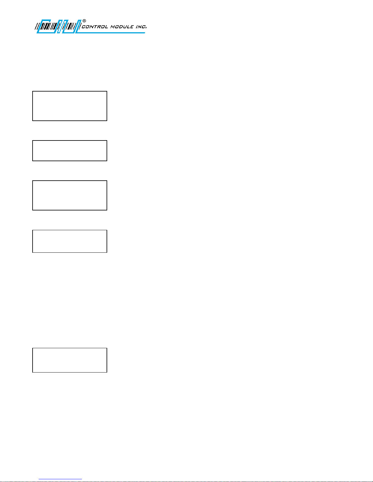
Several displays with the following messages appear in sequence during the normal G1 Terminal power-up
process. In addition, during power-up, the Genus G1 terminal also executes an internal firmware test.
G1 Loader splash screen displays program and version numbers.
Followed by Loading Genus.
The Genus splash screen displays program and version numbers.
Initializing Network displays the default IP of the terminal.
Initializing Flash displays and the IP address remains for reference, followed by Initialing RTC, Initializing System
Files and Initializing Java VM.
Online Mode
Following installation and power-up the G1 Terminal has completed the boot process and transitions to a Java
application that begins its functionality and data collection as defined by the user.
If no user defined program has been loaded the terminal will display the CMI reader setup application.
See Loading a Customer Defined Java Application in the Reference section of this document.
Revision C November 2016 17
Page 18
Genus G1 MARK II User Manual
Starting:
Up
Initializing:
Java VM
IP: 192.168.0.62
TERMINAL INFO?
<UP><DWN><E>
ENTER PIN:
<E-C>
UM3010-2
Offline Mode
The offline mode is utilized during installation and setup, when the functionality of the Genus Terminal needs to
be tested or if the communications setup requires a change. To accomplish this, the Terminal must be placed in
Offline Mode.
Entering Offline
(Online/Offline setup switch)
Entering offline mode can be accomplished in two ways, the easiest being to utilize the Online /Offline setup
switch on the back of the Terminal. However, pressing the ‘Clear’ and ‘Enter’ keys during the power-up
sequence as described below will also work with the Terminal.
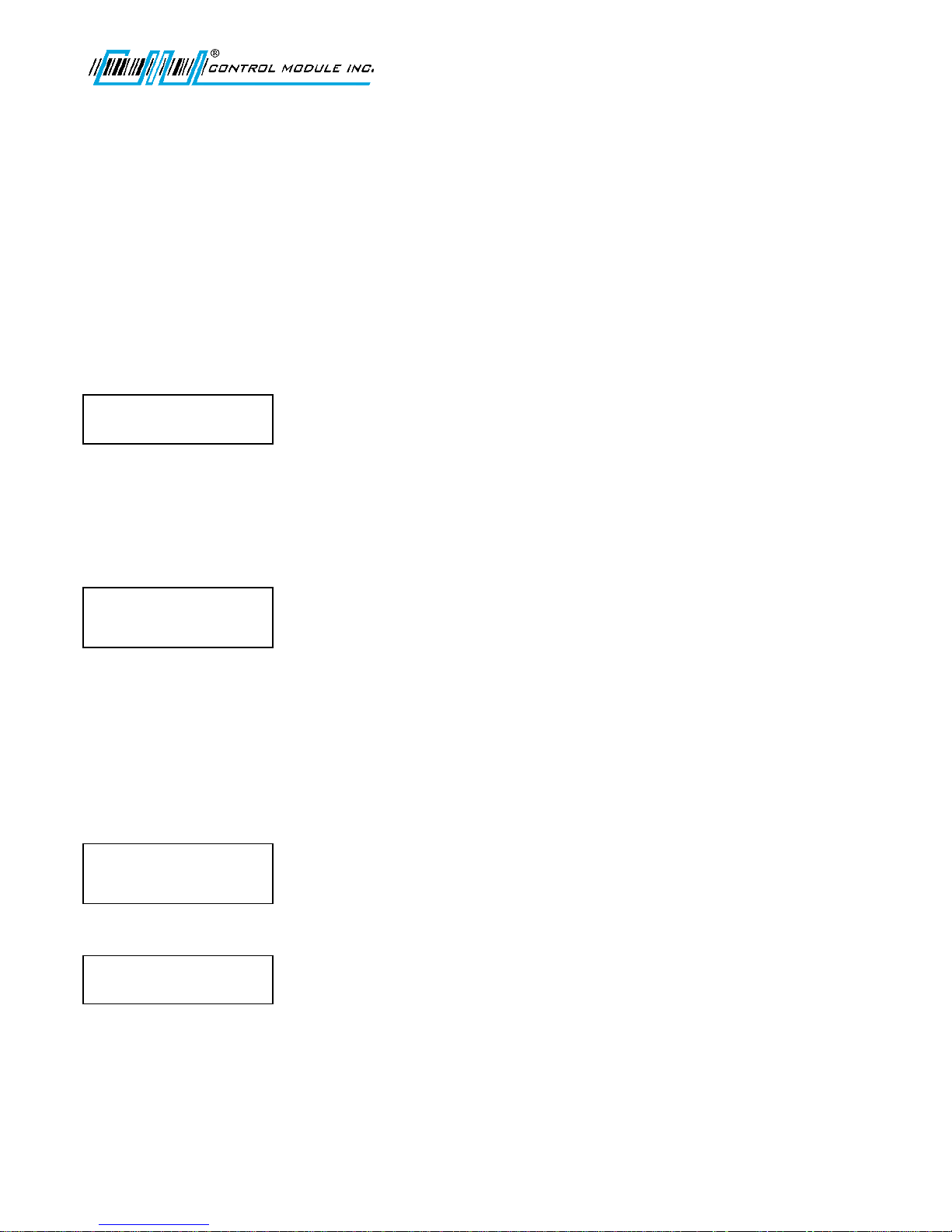
The following message indicates the terminal has entered into offline mode.
(Clear and Enter Keys during Power-up)
Offline Mode for the G1 Terminal Setup Mode is entered during power-up as the Terminal initializes.
Press the C and E keys simultaneously from the keypad during the second set of power-on beeps. These beeps
occur just after the following message:
At this point, as the Terminal beeps it will transition to the online application, unless the Clear and Enter keys
have been pressed.
Terminal Info Prompt
The Genus G1 Terminal stops and waits at the ‘Terminal Info’ prompt for keypad entry, as shown below, unless a
PIN number has been setup then the terminal will request a PIN:
No PIN Set:
PIN Previously Set:
Note: Enter PIN prompt will only appear if PIN number has been set up in SETUP PIN from the Main Menu during
a previous Offline session.
Revision C November 2016 18
Page 19

Genus G1 MARK II User Manual
Offline Setup Mode Menu Options
The following menu options for configuration changes become available when the terminal is
switched to offline.
TERMINAL INFORMATION
CLEAR RAM
CLEAR FLASH
NETWORK SETUP
WIFI NETWORK SETUP
WIFI NETWORK INFO
QUICK CHECK
COMM TEST
READER SETUP
SETUP PIN
SETUP TIME ZONE
DIAL-UP NETWORK
TADMIN SETUP
WEB SETUP
BIOMETRIC TEST (available when Biometric reader enabled)
EXIT SETUP
UM3010-2
Note: The Genus API provides the option to add user defined Setup Mode functions to
the existing menu options.
Revision C November 2016 19
Page 20

Genus G1 MARK II User Manual
UM3010-2
Keypad Layout
Key Activity
Use the arrow keys in Offline Mode to scroll through the Main Menu. Press E to select an option from the Main
Menu and follow directions displayed. Press the Home key while in the Setup screens to exit back to the Main
Menu options at the Terminal Info? Prompt.
Revision C November 2016 20
Page 21
Genus G1 MARK II User Manual
TERMINAL INFO?
<UP><DWN><E>
TERMINAL INFO?
<UP><DWN><H>
MACHINE NAME:
GENUS408300
Offline Mode – User Operational Displays
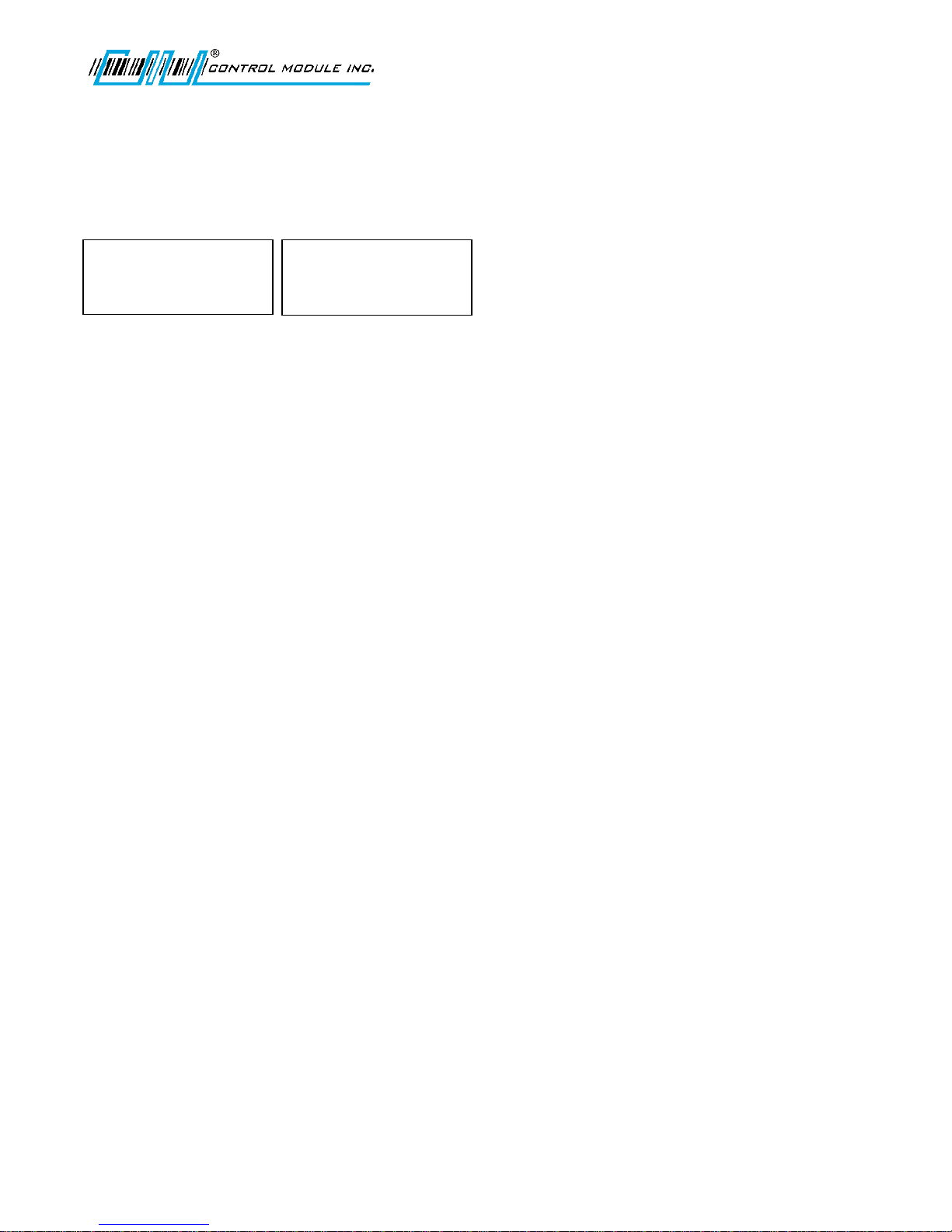
TERMINAL INFO
Provides basic terminal hardware information.
Press E to make a selection.
Use the up and down arrow keys to scroll through terminal information, such as:
Machine Name Terminal name assigned
MAC Addr Displays terminal’s MAC Address
Hardware Version For CMI reference
API Classes/API Version
Program Info Genus/System version
Serial No Provides service information
(Note: may not match terminal serial #)
MFGR Date For CMI reference
UM3010-2
Press H to return to the Main Menu. Use the down arrow key to scroll to the next menu item.
Revision C November 2016 21
Page 22
Genus G1 MARK II User Manual
CLEAR RAM?
<UP><DWN><E>
CLEAR RAM?
<E><H>
DATA WILL BE LOST!
‘E’=YES ‘H’=ABORT
UM3010-2
CLEAR RAM
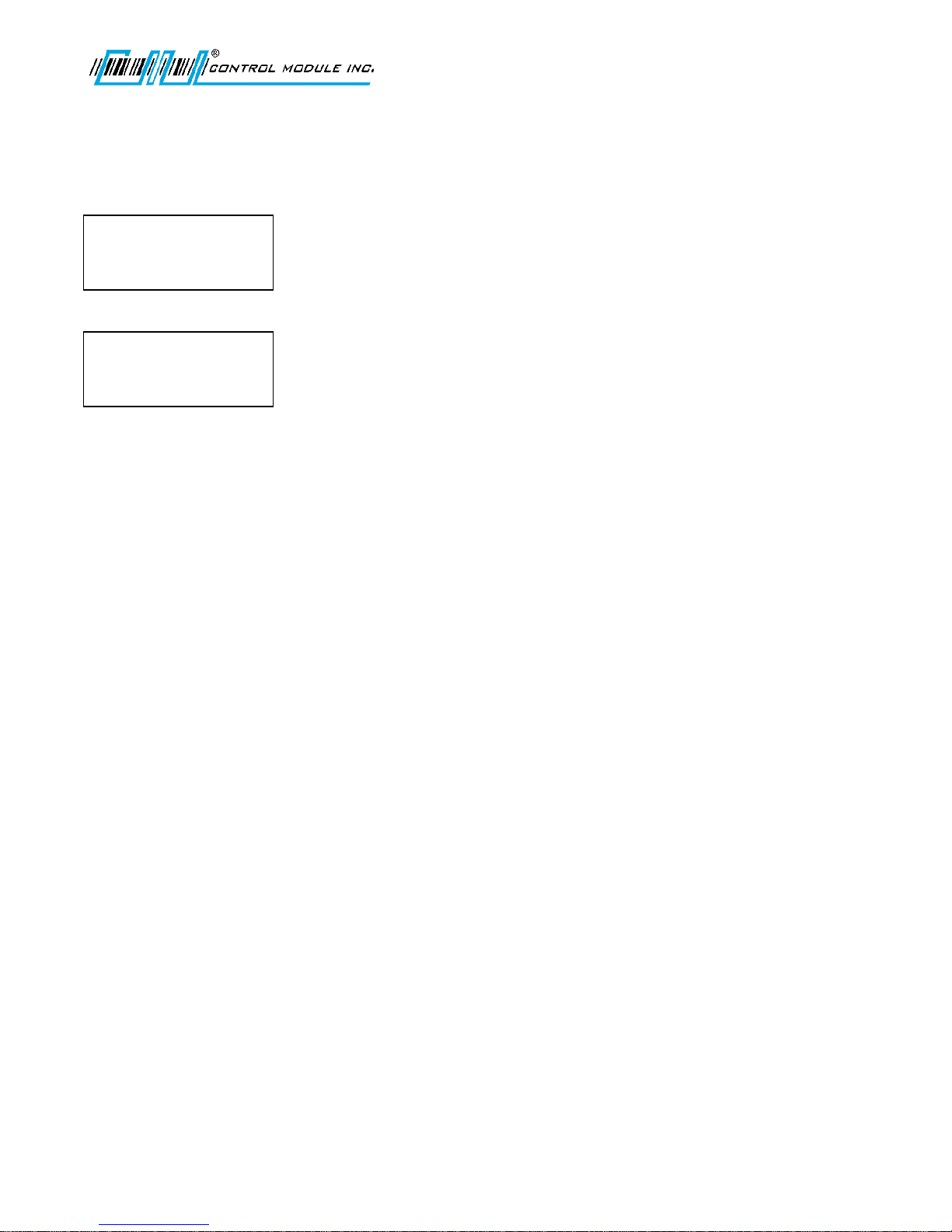
Clears the ‘\ramdisk’ on the terminal, typically erasing transaction data. See the File System Specification for
more detail on the data cleared.
Press E to select CLEAR RAMDISK.
Press E to CLEAR RAMDISK. Press H to abort.
If E is selected, a warning message displays. Press E again to CLEAR RAMDISK or press H to abort.
Revision C November 2016 22
Page 23
Genus G1 MARK II User Manual
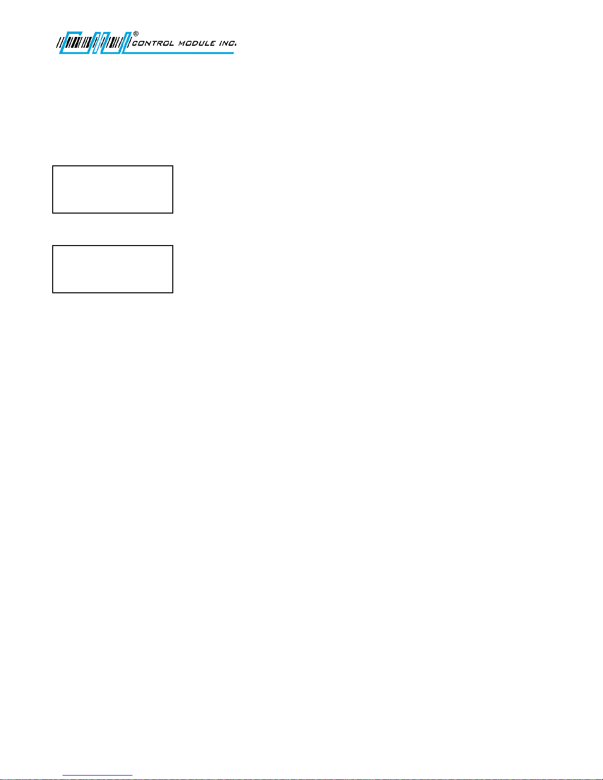
CLEAR FLASH?
<UP><DWN><E>
CLEAR RAM?
<E><H>
CLEAR FLASH?
‘E’=YES ‘H’=ABORT
UM3010-2
CLEAR FLASH
Clear Flash will clear the ‘\flashdisk’ on the terminal erasing everything except Classes.jar, App.jar, Genus App,
Lib1.jar, Lib2.jar, and Lib3.jar.
Note: This does not clear firmware or the user application.
Press E to select Clear Flash.
Press E to Clear Flash. Press H to abort.
If you select E, a warning message displays. Press E again to Clear Flash or H to abort.
Revision C November 2016 23
Page 24
Genus G1 MARK II User Manual
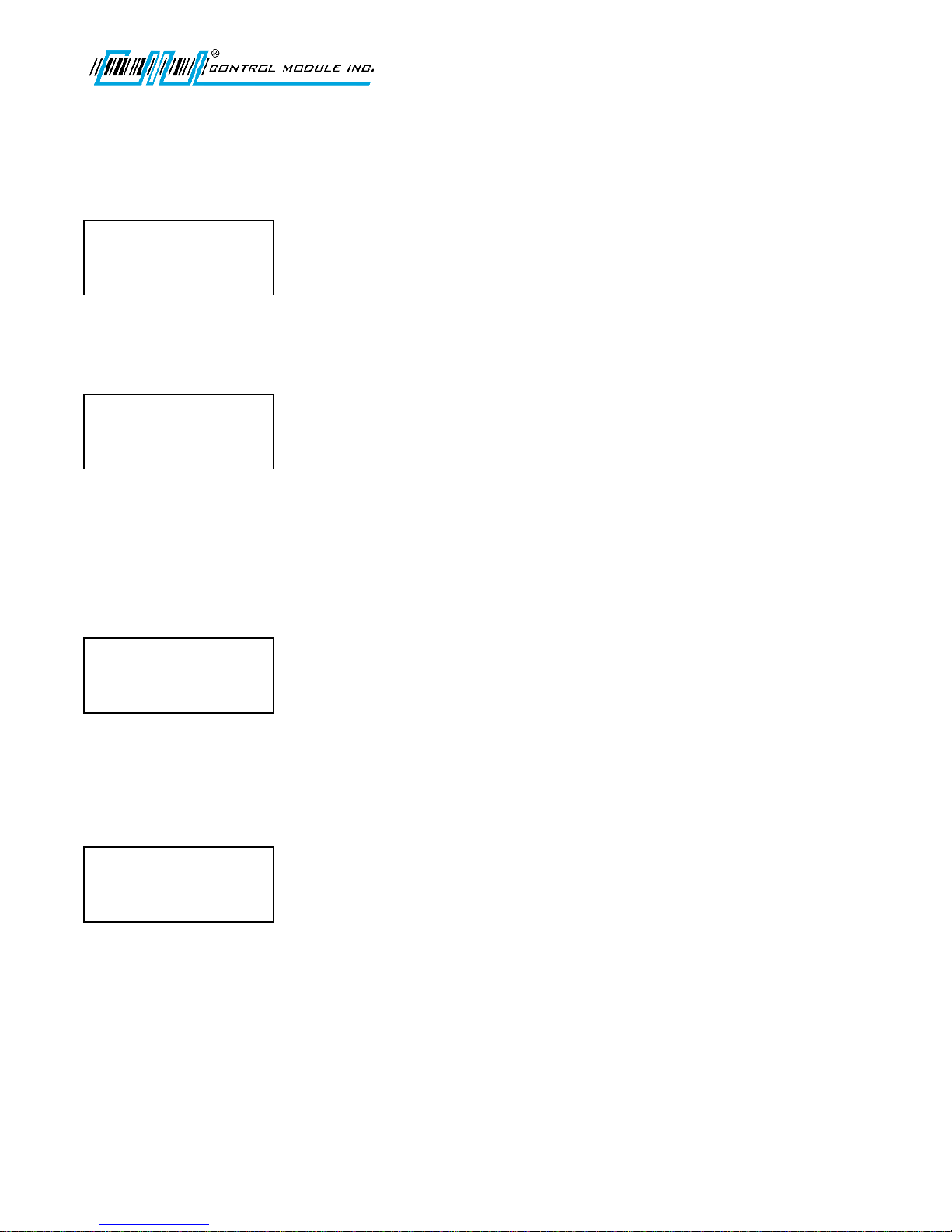
NETWORK SETUP?
<UP><DWN><E>
NETWORK SETUP?
<UP><DWN><E><H>
ENABLE DHCP
N
NETWORK SETUP?
<0-9><E><H>
TERMINAL IP:
192.168.000.064
NETWORK SETUP
<UP><DWN><E><H>
SUBNET MASK
255.255.255.000
UM3010-2
NETWORK SETUP
Network Setup provides the ability to configure the terminal’s network parameters, including DHCP, IP address,
gateway, subnet mask, DNS servers, and telnet menu.
Press E to select.
ENABLE DHCP
This turns on the terminal’s ability to obtain an IP address automatically from a DHCP server on the local
network.
Use the up and down arrow keys to set Yes or No. Set N to specify a static IP. Otherwise, set Y to advance to
ENABLE TELNET.
Press E to enter your choice and advance to the next setup option.
TERMINAL IP
Specify a static IP address. This screen will not appear if DHCP is enabled.
If DHCP is not enabled, then, use 0-9 and the right or left or arrow keys to advance or return through fields.
Press E to enter choice and advance to next network setup option.
SUBNET MASK
Specify a subnet mask for the terminal. This screen will not appear if DHCP is enabled.
Use the up or down arrow keys to scroll up or down through the valid subnet mask numbers. Press E to enter your choice and advance
to the next Network Setup option.
Revision C November 2016 24
Page 25
Genus G1 MARK II User Manual
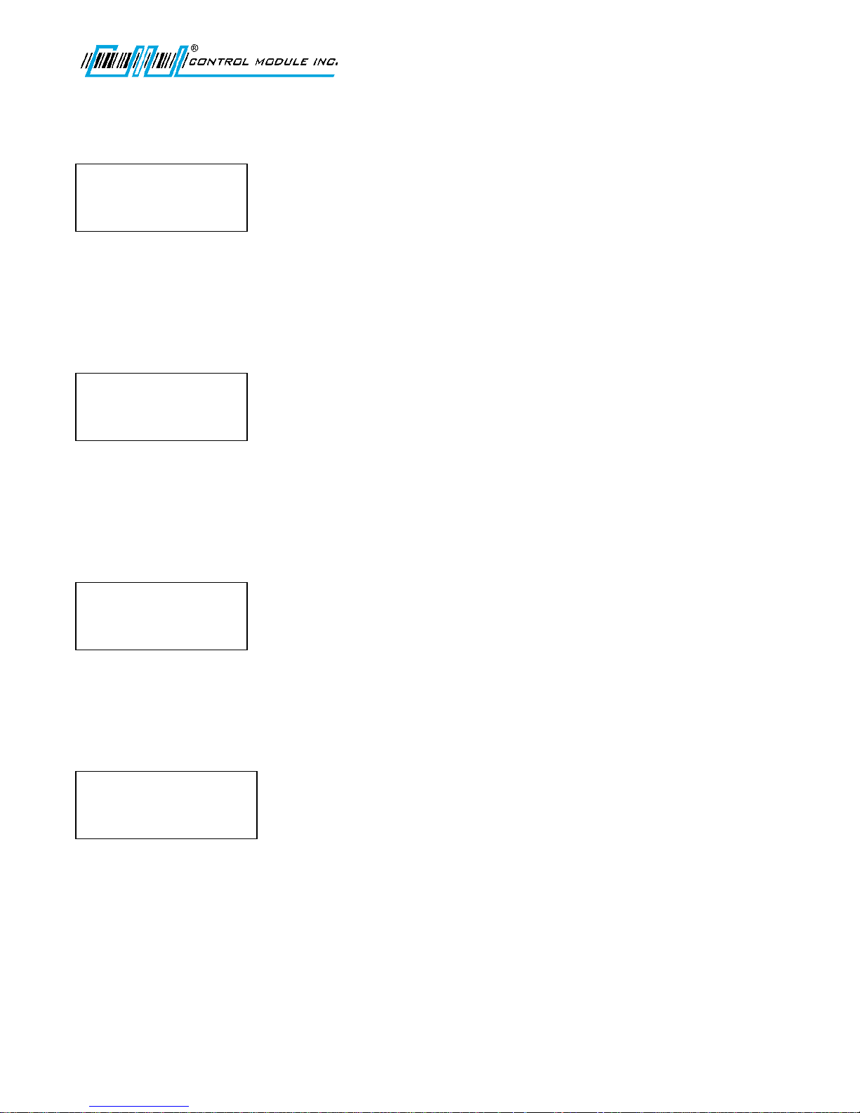
NETWORK SETUP
<UP><DWN><E><H>
GATEWAY
000.000.000.000
NETWORK SETUP
<0-9><E><H>
PRIMARY DNS:
000.000.000.000
NETWORK SETUP
<0-9><E><H>
SECONDARY DNS:
000.000.000.000
NETWORK SETUP
<UP><DWN><E><H>
ENABLE TELNET: Y
UM3010-2
GATEWAY IP
Specify a gateway address for the terminal. This entry is optional if the terminal does not need to communicate
with devices outside the immediate subnet. This screen will not appear if DHCP is enabled.
Use 0-9 and the right or left or arrow keys to advance or return through fields. Press E to enter choice and
advance to next network setup option.
PRIMARY DNS
Specify a primary Domain Name Server (DNS). This entry is optional if the terminal does not need access to DNS
services. This screen will not appear if DHCP is enabled.
Use 0-9 and the right or left or arrow keys to advance or return through fields. Press E to enter choice and
advance to next network setup option.
SECONDARY DNS
Specify a secondary Domain Name Server (DNS). This entry is optional if the terminal does not need access to
DNS services. This screen will not appear if DHCP is enabled.
Use 0-9 and the right or left or arrow keys to advance or return through fields. Press E to enter choice and
advance to next network setup option.
ENABLE TELNET
Enables the telnet interface to the terminal.
Use the up and down arrows to select Yes or No.
Revision C November 2016 25
Page 26
Genus G1 MARK II User Manual
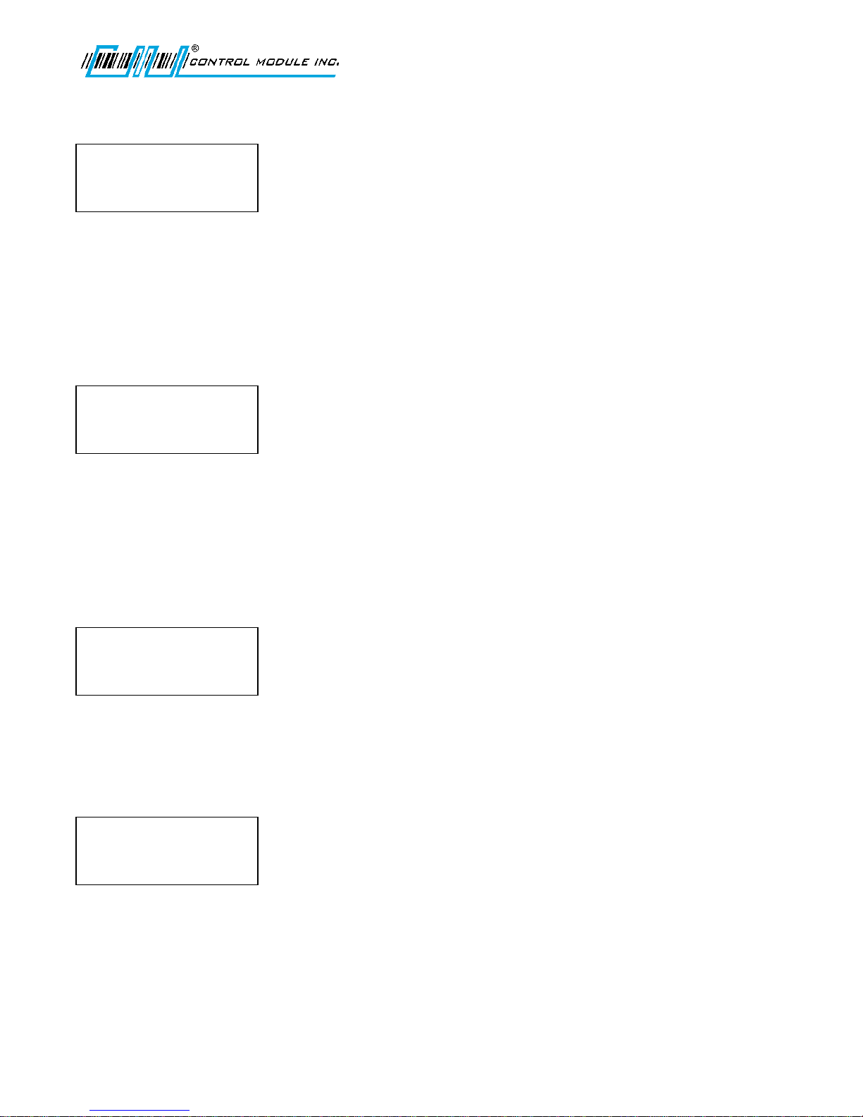
NETWORK SETUP
<0-9><E><C><H>
TELNET PORT:
09999
NETWORK SETUP
<0-9><E><C><H>
TELNET PIN:
NETWORK SETUP
<UP><DWN><E><H>
ENABLE TFTP:
N
NETWORK SETUP
<E><H>
SAVE CHANGES?
‘E’=SAVE ‘H’=ABORT
UM3010-2
TELNET PORT
Select a port to listen on for telnet configuration. This screen will not appear if the telnet interface is disabled.
Pressing C will zero out the Telnet port.
Use 0-9 and the right or left or arrow keys to advance or return through fields. Press E to enter choice and
advance to next network setup option.
TELNET PIN
Sets up a password for the Telnet configuration. This screen will not appear if the Telnet interface is disabled.
Note: This PIN differs from the Offline mode PIN.
Use 0-9 and the right or left or arrow keys to advance or return through fields. Press E to enter choice and
advance to next network setup option. Pressing C will clear the pin by backspacing one character at a time.
Note: The Telnet Password/Pin can only be 20 characters. If longer the Password/Pin will be truncated. See the
Reference Section in this document for additional Telnet information.
ENABLE TFTP
Enables a TFTP interface to the Terminal.
Use the up and down arrow keys to select Yes or No. Press E to choose and advance to the next Network Setup
option.
SAVE CHANGES
Saves all network changes.
Press E to save and H to abort any changes.
Revision C November 2016 26
Page 27
Genus G1 MARK II User Manual
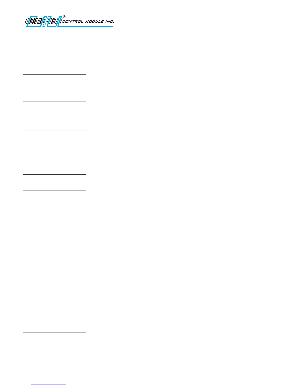
WIFI NETWORK SETUP?
<UP><DWN><E>
WIFI NETWORK SETUP?
Make sure Genus has a
valid IP address
WIFI NETWORK INFO?
<UP><DWN><E>
WIFI NETWORK INFO?
<UP><DWN><H>
LINK STATUS:
QUICK CHECK?
<UP><DWN><E>
WIFI NETWORK SETUP
This is explained in the WiFi section of this document.
Press E to enter the WiFi Setup.
Note: If an invalid IP address has been assigned, the following message might occur:
WIFI NETWORK INFO
WiFi information provides a resource for firmware and version releases and Link connectivity status.
UM3010-2
Press E to enter WiFi information. Use the up and down arrows to respond to prompts.
There are seven possible WiFi status messages:
Association Incomp.
Connected
Disconnected
AP change
AP out of range
AP in range
Association failed
QUICK CHECK
While in Quick Check mode the internal readers and wands attached to the wand port can be tested. If there are
values currently displayed, once a read takes place from a card or wand the values in the display are replaced by
the values from the card or wand read.
Press E to enter Quick Check.
Revision C November 2016 27
Page 28
Genus G1 MARK II User Manual
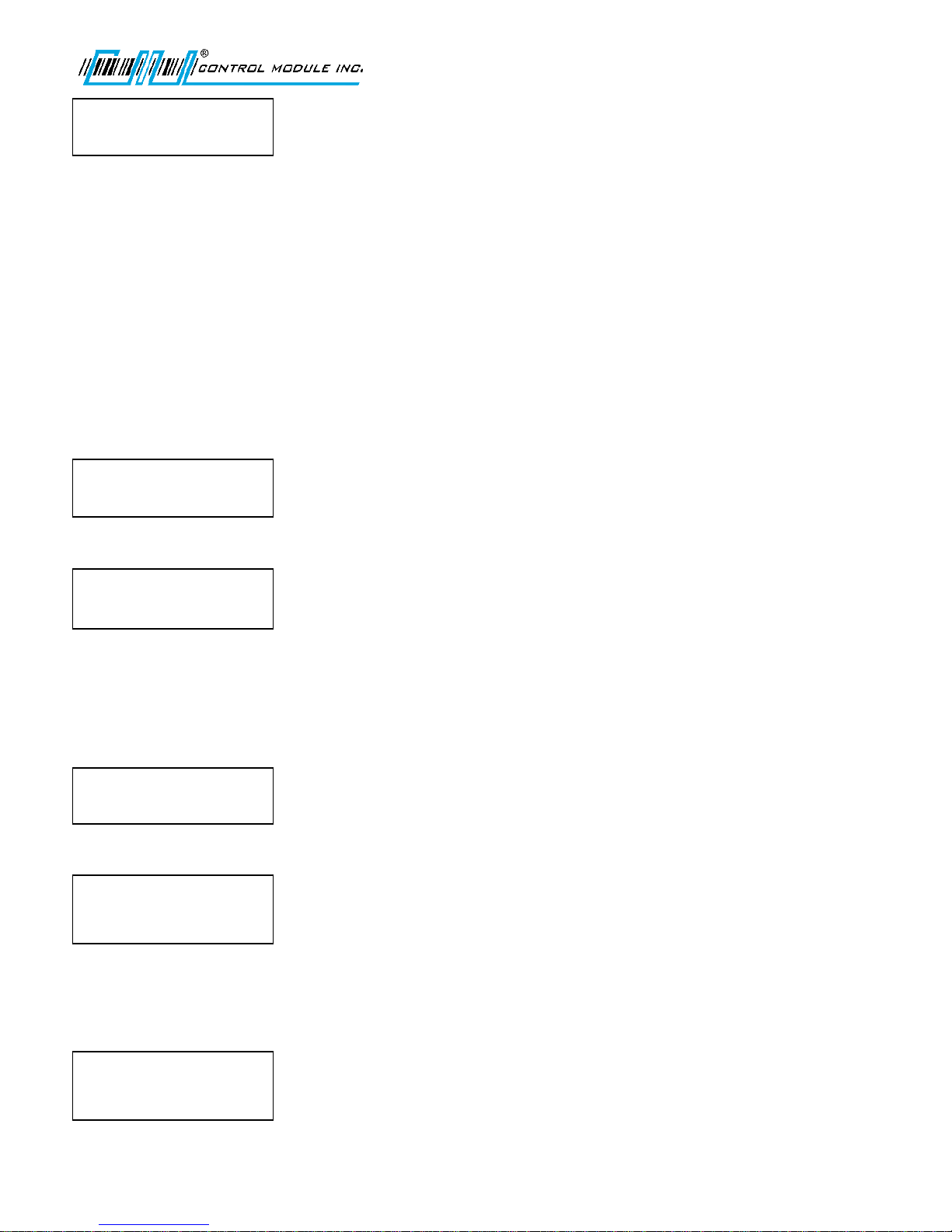
QUICK CHECK?
<0-9><E><C><H>
COMM TEST?
<UP><DWN><E>
COMM TEST?
<F1=MODEM><E=AUX><H>
READER SETUP?
<UP><DWN><E>
READER SETUP?
<UP><DWN><E><H>
SELECT INTERNAL RDR:
PROXIMITY
READER SETUP?
<UP><DWN><E><H>
SELECT EXTERNAL RDR:
BARCODE
UM3010-2
At this point, all key-presses except the E key will be echoed on the screen. Up to 40 characters can be entered
encompassing the lower two lines of the display. The top two lines of the display are reserved for terminal
messaging while in offline mode. Data is displayed from the lower right-hand corner and scrolls left. The data
wraps from the beginning of line 4 to the end of line 3. In this way, the most recently pressed key is always
displayed in the last character position on the screen.
Internal Smartcard readers MIFARE and iCLASS are auto detected as the terminal powers up and do not
require configuration under “Reader Setup”. The associated badges can be presented while in quick check to
establish whether a read and a good read tone occurs. The values returned are displayed in encrypted
format.
COMM TEST
Tests the Serial Aux port, which is used to connect to serial devices, such as a modem or a serial printer. This test
requires special test equipment. Contact CMI Technical Support for additional information.
Press E to select.
Note: Modem parameter configuration can be found in the Genus API documentation.
READER SETUP
Sets up the reader connected to the internal and external reader ports, and a barcode wand if connected to the
external wand port.
Press E to select.
Select the Reader Type for Internal and External readers. Use the up and down arrow keys to scroll through the
reader types.
Press E to save settings and advance to External reader setup.
Revision C November 2016 28
Page 29
Genus G1 MARK II User Manual
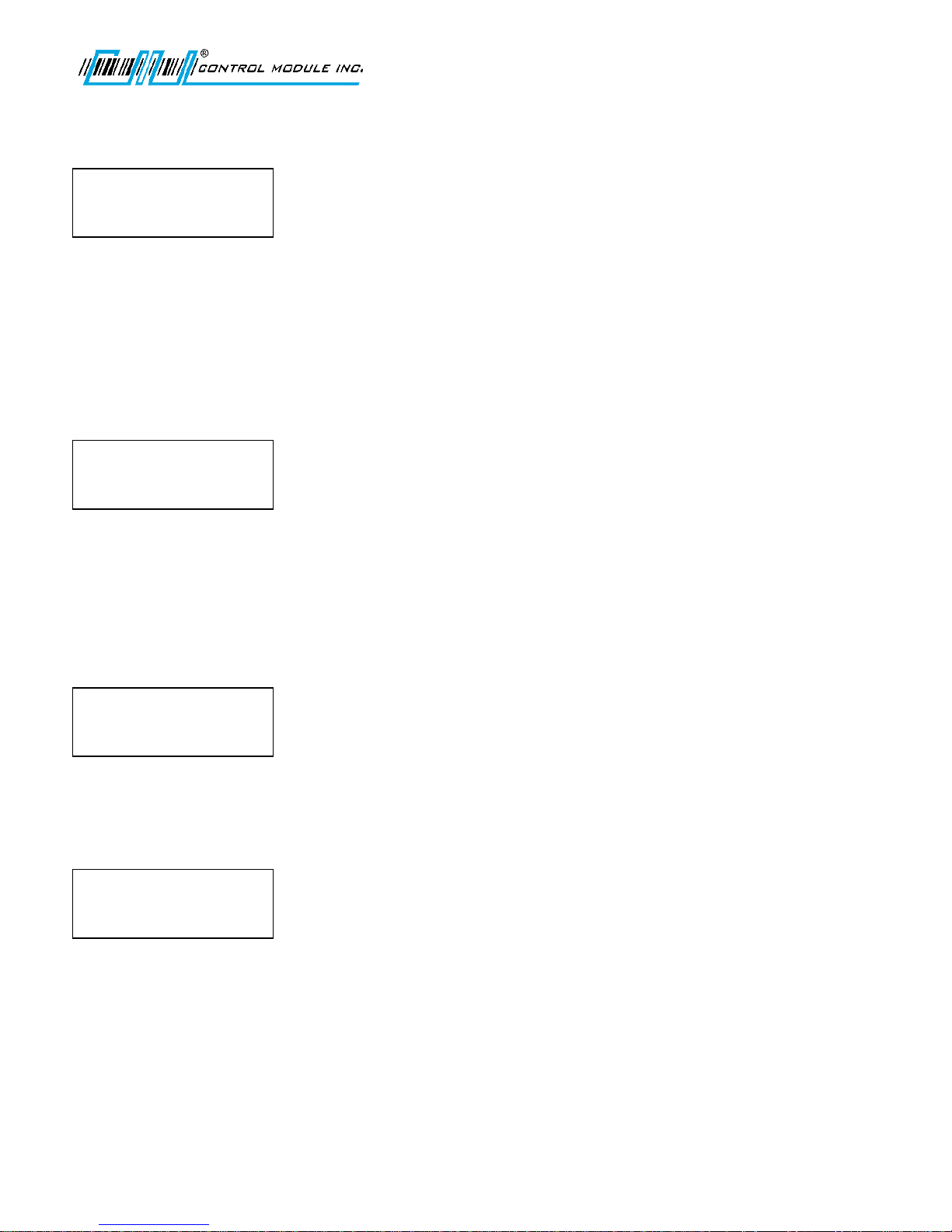
READER SETUP?
<UP><DWN><E><H>
SELECT WAND RDR:
NONE
READER SETUP?
<UP><DWN><E><H>
SELECT INTERNAL RDR:
BIOMETRIC
BIOMETRIC TEST?
<UP><DWN><E>
BIOMETRIC TEST?
<UP><DWN><H><E>
BIO VERSION?
UM3010-2
Note: The External reader configuration also supports WIEGAND OUT.
Press E to save settings and advance to Wand setup.
Use the up and down arrow keys to scroll through BARCODE or NONE.
Press E to save or H to abort any changes.
Biometric Reader
The Biometric Reader selection sets up the biometric reader connected to the internal reader port, and adds the
BIOMETRIC TEST to the top level setup menu after TERMINAL INFO?.
Select Internal Reader
Use the up and down arrow keys to scroll through the reader types and select BIOMETRIC. Press E to select.
The CONNECTING READER message displays and then returns you to the TERMINAL INFO? screen.
Biometric Test
Provides options to check the reader version, test the sensor or to calibrate the reader.
At TERMINAL INFO?, use the up and down arrow keys to scroll to BIOMETRIC TEST. Press E to select.
Press E to run the tests.
Bio Version
Returns the version of firmware loaded in the biometric reader.
Press E to select.
Revision C November 2016 29
Page 30
Genus G1 MARK II User Manual
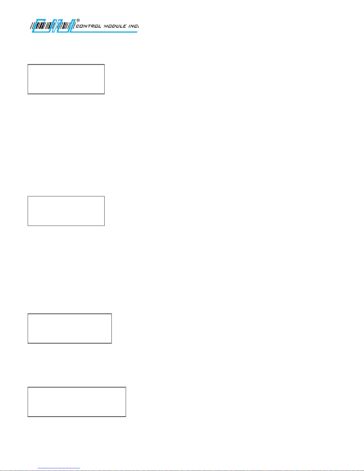
BIOMETRIC TEST?
<UP><DWN><H><E>
BIO SENSOR TEST?
PUT FINGER ON SENSOR
SETUP PIN
<0-9><E><H>
ENTER SETUP PIN:
<UP><DWN><E>
DIAL-UP NETWORK
<UP><DWN><H><E><C>
ALIASNAME ‘F1’=TST
‘E’=EDIT ‘C’=DELETE
DIAL-UP NETWORK
<UP><DWN><H><E><C>
NEW CONNECTION?
‘E’ = ADD NEW
UM3010-2
Bio Sensor Test
Verifies reader is functioning correctly.
The Terminal requests user to place a finger on the sensor to test. This occurs twice to verify the finger and
complete the test. If a new finger is used the message displayed will be VERIFY FAILED.
Calbrate Sensor
Generally, calibration of the Biometric sensor should not be required. Contact the CMI Service department
concerning the calibration of the Biometric sensor.
SETUP PIN
Personal Identification Number (PIN) that is used for security to prevent unauthorized entry into the setup mode.
Press E to select.
Use 0-9 to enter PIN.
Press E to save settings and return to Main Menu.
Note: To remove the SETUP PIN after it is assigned and saved, you must know the PIN to return to this screen.
Press C to clear and E to save the removal of the PIN.
DAIL-UP NETWORK
Sets up the information associated with the modem connections. Modem parameter configuration can be found
in the Genus API Documentation.
Use the up and down arrows keys to scroll through the dial-up aliases that were created during the
previous session.
To add a new connection, press E.
Revision C November 2016 30
Page 31
Genus G1 MARK II User Manual
NEW CONNECTION
<UP><DWN><0-9><E><H>
ALIAS:
SETUP TIME ZONE?
<UP><DWN><E>
SETUP TIME ZONE?
<UP><DWN><E><H>
SELECT TIME ZONE:
EST
WEB SETUP?
< E><H>
WEB SETUP
<UP><DWN><E><H>
ENABLE WEB PAGES:
Y
UM3010-2
Use the 0-9 numeric keys to enter a phone number. A combination of the scroll keys for alpha and the
numeric keys can be used for Login, Alias and Password. Use the up and down arrow keys to scroll for
alpha and special characters. Use 0-9 for values.
Press E to accept. All settings are immediately saved.
SETUP TIME ZONE
Sets the time zone that terminal resides in.
Press E to select.
Use the up and down arrow keys to select your time zone.
Press E to save settings and return to the Main Menu.
WEB SETUP
Web Setup enables communication for Web Services on the Terminal, and between the host system and the
Terminal.
Note: These settings can be configured here in Offline Mode or through the Web Browser via the terminal IP.
Press E to select.
Use the up and down arrows to enable (Y) or disable (N) each option.
Press E to save and advance to the next option.
Enable Web Pages - This option enables the terminal's web configuration interface allowing an individual to
remotely manage a number of options in the terminal via a web page. For more details on using the web
configuration interface, please see the Web Browser Interface section of this document.
Revision C November 2016 31
Page 32
Genus G1 MARK II User Manual
EXIT SETUP?
<UP><DWN><E>
UM3010-2
Enable Web Services - This option enables the terminal's web services functionality. When enabled, the terminal
will allow the use of built-in web services functions called by a host.
Enable Host Web Svc - This option enables the terminal's ability to use web services on a host computer. When
this is enabled, the terminal will attempt to connect to the configured URLs to send and receive data, including
transactions. While this enables the feature at the terminal level, the terminal application must utilize these
features.
Enable Modem - Note: this option is only available when "Enable Host Web Svc" is set to "Y". This option enables
the use of the modem to deliver data over the Host Web Service interface. If enabled and data is available or calls
are made to the web service, if a connection is not present, the host will dial out in an attempt to transmit or
receive data.
EXIT SETUP
Exits Offline Mode and returns to the power-up sequence.
Press E to exit Setup and reboot the terminal.
Revision C November 2016 32
Page 33
Genus G1 MARK II User Manual
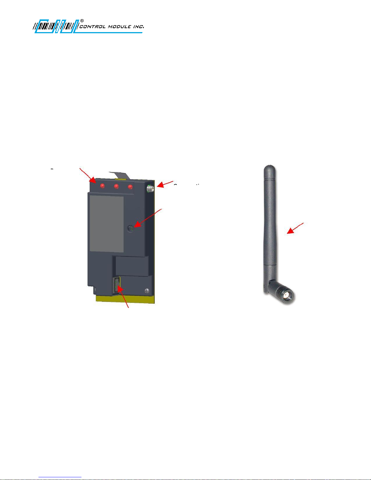
Antenna
Status LEDs
Comm, Link,
Antenna
Cable
Reset
Switch
UM3010-2
Genus WiFi
The 3046 WiFi Module provides wireless network connectivity for the CMI Genus series terminals. The WiFi
Module functions as an Ethernet to Wireless LAN bridge and connects to the Genus terminal’s RJ-45 Ethernet
port. The WiFi Module will provide a seamless connection to an 802.11b compliant Access Point (AP) that is within
range. This WiFi Module is compliant with the IEEE 802.11b standard and provides security and encryption
functions for a secure and reliable network.
This section of the document describes the Genus WiFi setup. It also provides troubleshooting information and a
Code 39 barcode table to assist in the setup of the Module using a digital barcode wand. This provides easy access
to special characters that are not available on the Genus terminal keypad, but may be required for SSID, WEP
Keys, and other security parameters.
Please note that the WiFi Module may be referred to as “Module” within this section of the document.
Revision C November 2016 33
RJ45 for CAT-5
Connection to
GenusTerminal.
(Ethernet Cable
Supplied)
Page 34

Genus G1 MARK II User Manual
IP address:
192.168.0.68
Subnet Mask:
255.255.255.0
Gateway IP:
0.0.0.0
UM3010-2
Genus WiFi Configuration/Setup
WiFi Module
The WiFi Modules are shipped with DHCP disabled, and all security modes turned off. If the Module successfully
associates with an access point, the Link and Power LEDs will be green. If the Module is unable to associate with
an access point, the Link LED will blink red and the Power LED will be green in color.
IP Addresses
There are two IP Addresses involved in the WiFi configuration. The WiFi Module and the Terminal each have a
unique IP.
WiFi Module - Fallback
If DHCP is enabled and the WiFi Module has been powered up for 60 seconds without being able to associate with
an access point, the Module will fallback to the following settings:
When the Module reaches the 60 second timeout, it will revert back to the fallback settings. The Power LED will
change from amber to green and the Link LED will continue to blink red.
Genus Terminal
The Genus terminal must also have a valid IP address (Terminal DHCP turned off) in which the first three octets
are 192.168.0.XXX, otherwise the Terminal will not be able to communicate with the WiFi Module installed.
Change the IP address on the WiFi Module first. Note that the terminal will “hang” if on a different sub-net.
DHCP and WiFi Module setup
Upon entering setup mode the user is given the option to enable (Yes) or disable (No) DHCP for the WiFi Module.
If DHCP is disabled, the Terminal will prompt the user to enter network settings for the Module. These settings
are stored by the Terminal allowing it to be able to go back into setup again as needed. If DHCP is enabled, and
the Module is assigned an IP address by the DHCP server, the Terminal will not know the Module’s IP setting and
will not be able to go into setup.
However, the need to go back into setup once the Module associates with an access point and is running is
unlikely. If there is a need to go into setup, the access point would have to be powered down or the Terminal
would have to be moved out of range. After 60 seconds, the WiFi Module will revert back to its fallback settings
and the user will be able to go into setup.
Revision C November 2016 34
Page 35

Genus G1 MARK II User Manual
UM3010-2
SETTING UP WIFI
The Genus terminal needs to be in the Offline mode to get to the WiFi setup.
Enable DHCP: No – disables DHCP and requires the user to enter network parameters. Yes – enables DHCP and
the network parameters are assigned by the DHCP server.
With DHCP disabled the Terminal will prompt for network settings: Subnet Mask, Gateway IP, Primary DNS and
Secondary DNS. Enter these values using the 0-9 keys on the terminal.
IP: This is the IP address of the WiFi Module.
Note: To communicate to the Terminal you need to use the Terminal IP, which is assigned through the Network
Setup menu.
SSID: The default value for the SSID is “any”. The SSID can be up to 31 characters. This controls which AP the
Module connects to. If using a digital wand refer to the Code 39 Programming Table in this document.
Note: The SSID is case sensitive.
Security Type: The default is set to disabled. However, the Module provides, wep64, wep128, wpa-psk, options.
See WiFi Module Security Settings, in this manual.
Save Changes? Changes saved by ‘E’ will be saved to the WiFi Module. ‘H’ aborts the setup changes placing the
user at the first prompt for DHCP enable/disable.
WiFi Module Fallback Settings
Fallback mode can occur when the WiFi module is unable to associate with an access point after 60 seconds.
When fallback occurs the Terminal recognizes the fallback settings and will allow a setup session to change the
WiFi parameters.
WiFi Module Fallback LED Indication
The LEDs on the Module revert to the Power LED, changing from amber to green, and the Link LED will continue
to blink red.
Enable DHCP: If fallback has occurred, choosing Yes while in WiFi Network Setup will bring up the FALLBACK
SETTINGS prompt. If Yes is entered, the fallback settings stored in the Module become available to change. If No,
the Module returns to the SSID prompt.
Fallback IP: Default is 192.168.000.068
Fallback Subnet: Default is 255.255.255.0
Fallback Gateway: Default is 000.000.000.000
Revision C November 2016 35
Page 36

Genus G1 MARK II User Manual
UM3010-2
WiFi Module Security Settings
The WiFi Module provides security setting options. The WiFi Module default for the security settings is set to
disabled. This provides the user with the option to choose a security type and allows corresponding fields to be
available to enter settings for that security type.
Scroll through the security types, wep64, wep128, wpa-psk, and disable. Press E to choose.
WPA-PSK refers to Pre-Shared Key used in Authentication. This is a shared key between the station and the access
point (AP) and is entered as a passphrase. Input is 8 to 63 ASCII characters or 64 hex characters that cannot
contain spaces. The passphrase must match the passphrase on the AP. When the passphrase has been entered
use either ‘E’ to Save or ‘H’ to Abort. If using a digital wand, refer to the Code 39 Programming Table in this
document.
Note: The G1 Terminal requires the exact number of hex characters for WEP key values to advance to the next
parameter setting.
WEP64 refers to 64-bit key length assigned to the WiFi Module that must match the access point on the network.
The WEP Authentication type can be configured for auto, open or shared. Auto is the default and will
automatically detect the authentication. Open authenticates using open Key algorithm, and will communicate the
key across the network. Shared authenticates using Shared Key algorithm, and will allow communication only
with devices with identical WEP settings.
The Default Key option must match the key index configured on the Access Point. The options are 1, 2, 3, 4, with
the default set to 1.
There are four WEP Key input areas to add the ASCII HEX values. These correspond to the numbers as chosen
through the default key above. WEP 64 requires 10 hex digits. Default is shown.
Acceptable characters include only 0-9, and A-F, in upper case.
If using a digital wand refer to the Code 39 Programming Table in this document.
When desired changes have been entered use either ‘E’ to Save or ‘H’ to Abort.
WEP128 refers to 128-bit key length assigned to the WiFi Module that must match the access point on the
network.
Wep128 works the same as wep64 described above with a requirement of 26 ASCII HEX digits that must be
entered in the Wep Key areas 1-4.
Revision C November 2016 36
Page 37
Genus G1 MARK II User Manual
UM3010-2
Web Browser Interface
The web browser interface provides system administrators with the ability to remotely login, view and change
system parameters and settings on the Terminal.
Navigation hierarchy:
Home page (Genus Administration)
Network Setup
Web Service Setup
Data Maintenance
Debugging
Logon
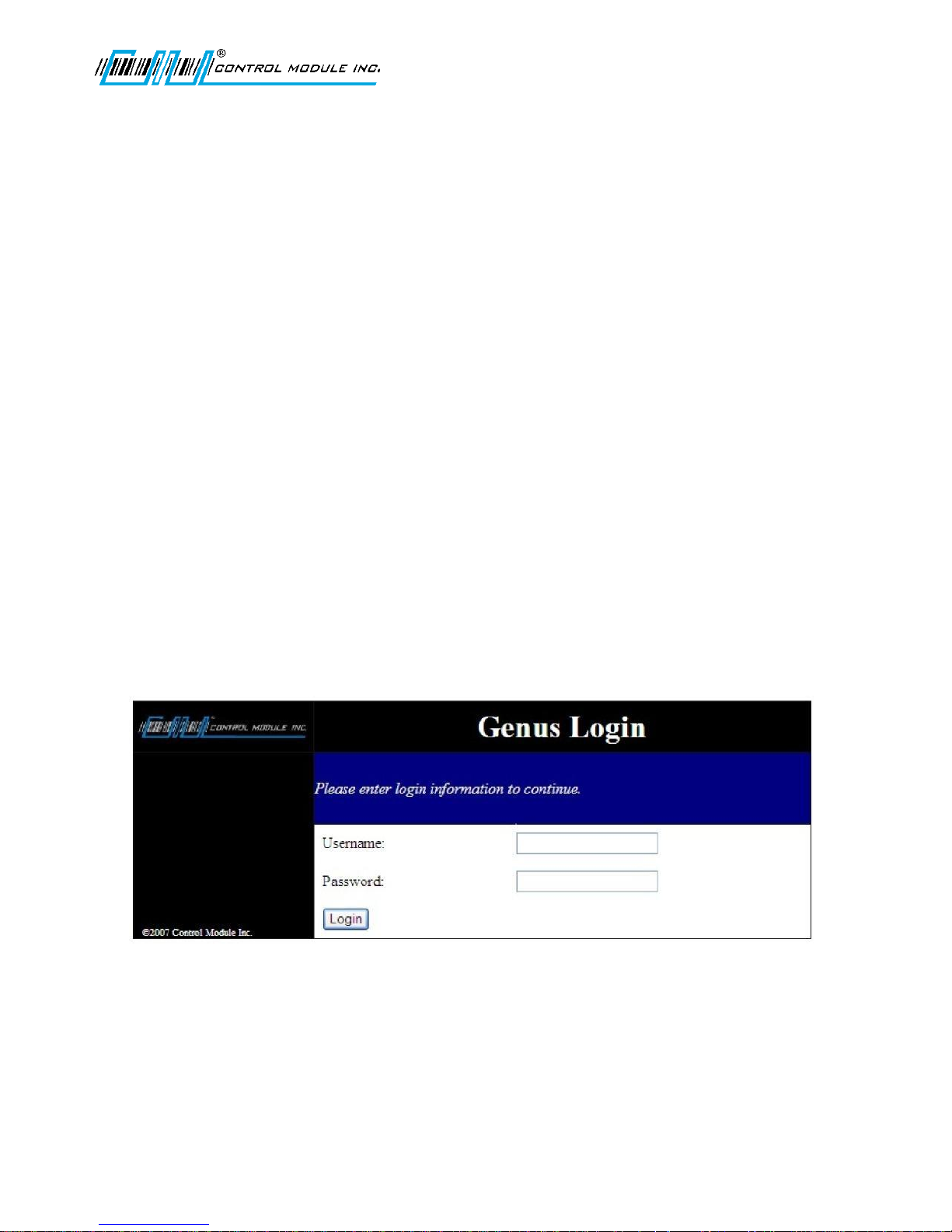
Provide verification and session management requiring a user name and password before allowing access to
system functions. The logon screen simply displays a prompt screen for a username and password. A limit to
the number of logon attempts from the same machine over a period of time will restrict brute force password
attacks. For the sake of simplicity there is only one administrator account.
Username and password are generic by default and should be changed for future sessions of the Terminal Web
Browser Interface. Username and Password are not case sensitive.
Username:Admin
Password:Pass
Note: A Web Browser Interface session will continue until there is either a timeout after 10 minutes of
inactivity or will become invalid if the terminal is rebooted. Close the Web Broswer and re-open to start
a new session.
Revision C November 2016 37
Page 38
Genus G1 MARK II User Manual
UM3010-2
Home page – Genus Administration
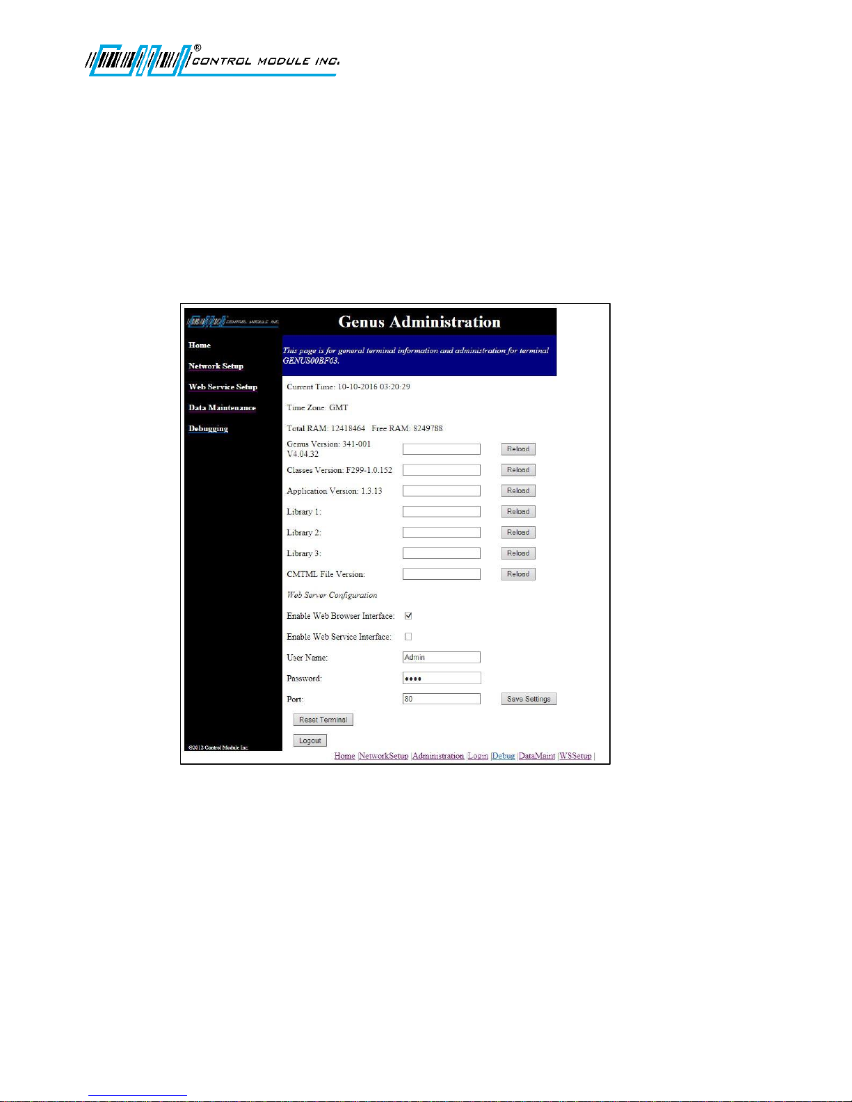
Once logged in to the terminal the Genus Administration home page is displayed. The Genus Administration
page displays the following information as retrieved from the current Terminal session or as used during a
previous session and retained in the browser.
Current Time • Application Version (App.jar)
Time Zone • Library Filenames (Lib1.jar, Lib2.jar, Lib3.jar)
Terminal memory (RAM) • CMTML File Version
Genus Version • Enable Web Browser & Service Interfaces
Classes Version (Classes.jar) • User name and ‘*’ encoded password
Current Time
The Current Time and date displayed is normally set by the host and cannot be changed in the Web Browser
Interface.
Revision C November 2016 38
Page 39

Genus G1 MARK II User Manual
UM3010-2
Time Zone
The Time Zone is normally set during Terminal setup and cannot be changed in the Web Browser Interface.
Total RAM
The Total RAM displayed refers to the total amount of dynamic RAM available for program execution. Free
RAM refers to the amount of dynamic RAM remaining at that point in time.
File Versions and Fields
The fields adjacent to the Genus Version, Classes Version, Application Version, Lib 1, 2, 3 and CMTML File
Versions are editable fields that accept a URL to point to a new version of that file represented. The Reload
button uses the URL to retrieve the new file and loads it to the Terminal. A URL example could be as follows
‘www.example.com/genus’. More than one file can be reloaded during a session. When all reloads are
complete the Terminal can be rebooted by selecting the Reset Terminal button at the bottom of the Genus
Administration page.
Web Server Configuration
The Web Server Configuration Section has two settings Enable/Disable Web Browser Interface and
Enable/Disable Web Service Interface. The Enable Web Browser Interface is enabled by default and the
checkbox is checked. The Enable Web Service Interface setting is independent of the Browser and is disabled
by default. The checkbox is not checked.
Note: Both Settings Enable Web Browser Interface and the Enable Web Service Interface can also be set
through the Web Setup in Offline mode on the Terminal.
User Name and Password
Username and password fields are provided and should be changed from the Username and Password defaults
configured on the Terminal. Username and Password is not case sensitive.
Port
Port is the default (web port) TCP port for the Web Browser Interface.
Save Settings Button
Settings changed on the Genus Administration page are saved to the Terminal when this is selected.
Reset Terminal
This is required to have new settings take effect. Some settings may take some time to complete. If the
Terminal is reset the Web Browser should also be closed and restarted to pickup any new settings. Settings
should be saved prior to resetting the Terminal.
Logout
Will logout from the current session. If changes are made on the Genus Administration page and not saved
they will be lost during logout.
Revision C November 2016 39
Page 40
Genus G1 MARK II User Manual
UM3010-2
Network setup
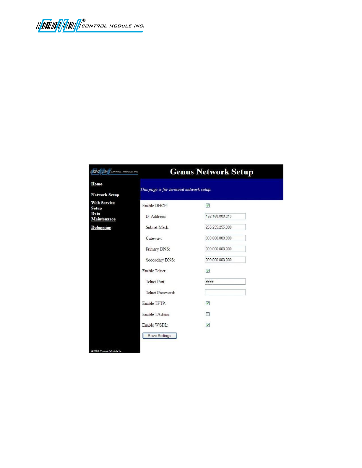
The network setup screen provides standard network setting fields to allow administrators to configure the
terminal’s network parameters. All settings on the Network Setup page except the ‘Enable WSDL’ correspond
to the Offline Setup menus in the Terminal.
Network parameters include:
DHCP enable/disable - check box • Telnet port – text input
IP Address – text input • Telnet password– text input
Subnet mask – text input • TFTP enable/disable - check box
Gateway – text input • Checkbox to enable/disable TAdmin
Primary DNS – text input • Checkbox to enable/disable Web
Secondary DNS – text input Service Description Language (WSDL) response
Telnet enable/disable - check box • A button to Cancel or Save settings
Note: If DHCP has been enabled the IP address is filled in by the DHCP server. Subnet Mask, Gateway, Primary
and Secondary DNS will not be available to change. The Telnet Password/Pin can only be 20 characters. If
longer the Password/Pin will be truncated.
Revision C November 2016 40
Page 41
Genus G1 MARK II User Manual
UM3010-2
Web Service Setup
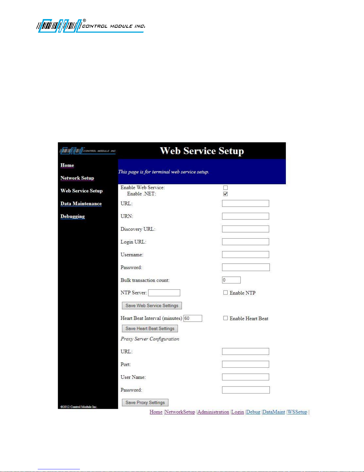
The Web Service Setup screen provides system administrators with the ability to reconfigure the Terminal
settings for host side web service. This page provides a listing of all configuration name/value pairs with the
ability to edit, add, or remove entries.
URL • Bulk transaction count
UR N • Pr ox y U RL
Logon credentials (username and password) • Proxy - Port
Discovery URL • Proxy Username and Password
Revision C November 2016 41
Page 42

Genus G1 MARK II User Manual
UM3010-2
Enable Web Service
This setting will enable the Web service setup for the host side. The Enable Web Service corresponds to the
Enable Host Web Service option in the Offline Setup on the Terminal.
Discovery URL
The Discovery URL is the URL the Terminal will use to download its web service connection information. This
URL should return the web service configuration information. For more information, please review the Genus
Web Services Developer’s Guide.
Bulk Transaction Count
This setting defines the number of transactions sent to the host in an XML message.
Revision C November 2016 42
Page 43
Genus G1 MARK II User Manual
UM3010-2
Data Maintenance
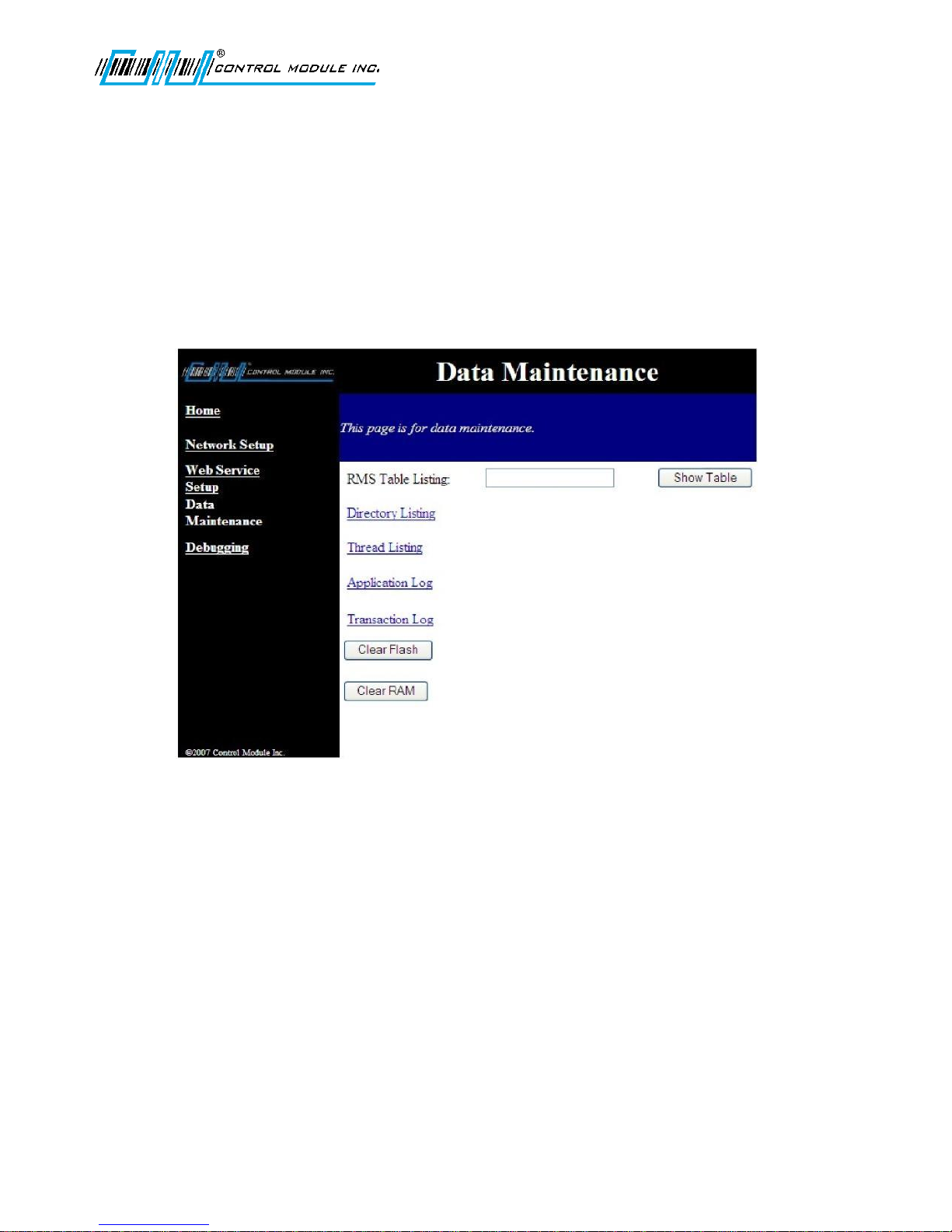
The data maintenance screen provides directory browsing and Record Management System (RMS) browsing
that would generally be used for support or development. The following pages provide sample screen shots for
Directory Listing, Thread Listing, Application Log, and the Transaction Log.
RMS Table Listing
The RMS Table Listing is located on the ‘\flashdisk’ and provides access to data tables that are setup by user
applications.
The data field adjacent to RMS Table Listing is for the table name and is case sensitive. If a large table is
requested it may take a few minutes to load. Select ‘Show Table’ once the table name has been filled in.
Clear Flash
This will clear the ‘\flashdisk’ on the terminal erasing everything except Classes.jar, App.jar, Genus App,
Lib1.jar, Lib2.jar, and Lib3.jar. This is also available in the Offline Setup mode of the Terminal. A warning
message for loss of data will display if the Clear Flash button is selected.
Revision C November 2016 43
Page 44

Genus G1 MARK II User Manual
UM3010-2
Clear RAM
This will clear the ‘\ramdisk’ on the terminal, typically erasing transaction data. A warning message for loss of
data and transactions will display if the Clear RAM button is selected.
Note: After a ‘Clear RAM’ the Terminal requires a reboot to complete the process.
Directory Listing
The Directory listing allows you to view files and directories that currently reside in the ‘\ramdisk’ on the
terminal. This is a sample directory your directory list may differ.
Directory/
javahome/
system/
etc/
errors.txt (1.17KB)
transacts.dat (500.11KB)
data/
javahome Contains the time zone configuration file tz.conf. Modified by CMI personnel only.
System system/log- contains the Application Log. Viewed by clicking on the ‘Application Log’ link on
the Data Maintenance page
Etc etc/app – contains application.conf. Configuration settings for the application.
etc/tadmin – contains tadmin.conf.
errors.txt a file containing informational and error messages useful for troubleshooting. Contains generic
Genus messages and application specific messages. Primarily intended for CMI support
personnel.
transacts.dat The transaction queue in a proprietary data format. Contains generic transactions like ‘APP
STARTED’ or ‘RE-CONNECTED’ plus application-specific transactions. Can be viewed by using
the ‘Transaction Log’ link on the Data Maintenance web page.
Data Application specific data folder.
Note: The contents displayed in the ‘Directory’ listing can change depending on the application, or version of
the Genus1 class library loaded in the terminal.
Revision C November 2016 44
Page 45
Genus G1 MARK II User Manual
UM3010-2
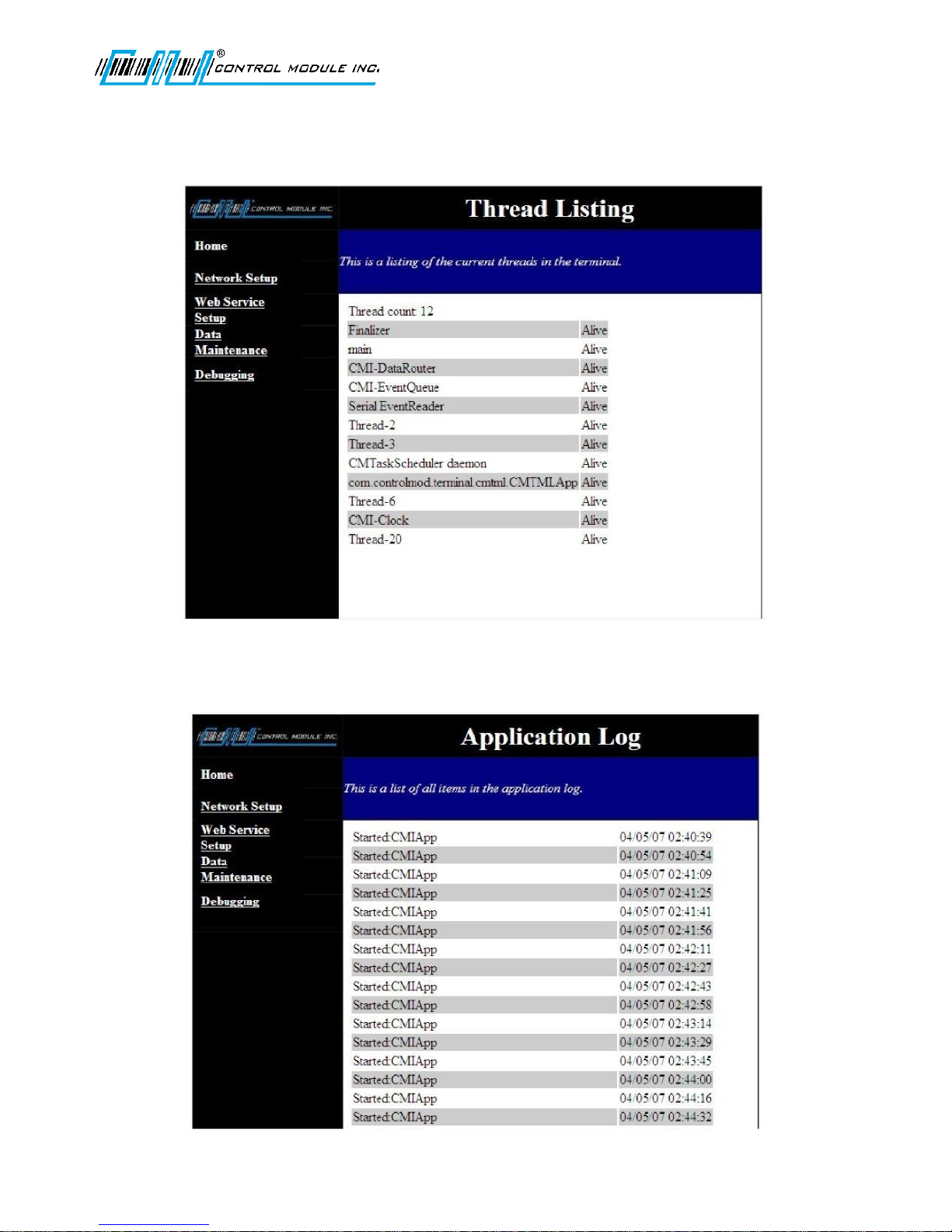
Thread Listing
The Thread Listing will display all active threads in the Terminal that are currently running. This is a sample
screen your display of active threads may differ.
Application Log
The Application Log will display any application starting messages and critical system messages.
Revision C November 2016 45
Page 46
Genus G1 MARK II User Manual
UM3010-2
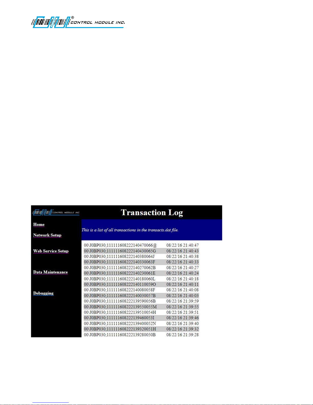
Examples:
Message: Started:(application universalresource name‘urn’)mm/dd/yy hh:mm:ss
Description: Date and time the application identified by a simple name, or urn, for example:
com.controlmod.demo.App
Message: PS00354D000@x mm/dd/yy hh:mm:ss
Description: A terminal power on event. PS is the internal ‘P’rom’S’et number of the firmware.
x = 1 ( hardware reboot when power is applied to the terminal )
x = 0 ( software reboot due to reloading a system or application file, or reboot from the setup
web pages)
Message: WebReboot NetworkSave mm/dd/yy hh:mm:ss
Description: A software reboot of the terminal due to changes in the network configuration executed through
the setup web pages.
Message: WebReboot ServiceReset mm/dd/yy hh:mm:ss
Description: Logged when a host invokes the Reset() command of the terminal’s web service functions.
Transaction Log
The Transaction Log will display the type, name, date and timestamp for each transaction that occurs and are
currently stored in the data queue. Up to 50 transactions can be displayed per page.
Revision C November 2016 46
Page 47
Genus G1 MARK II User Manual
UM3010-2
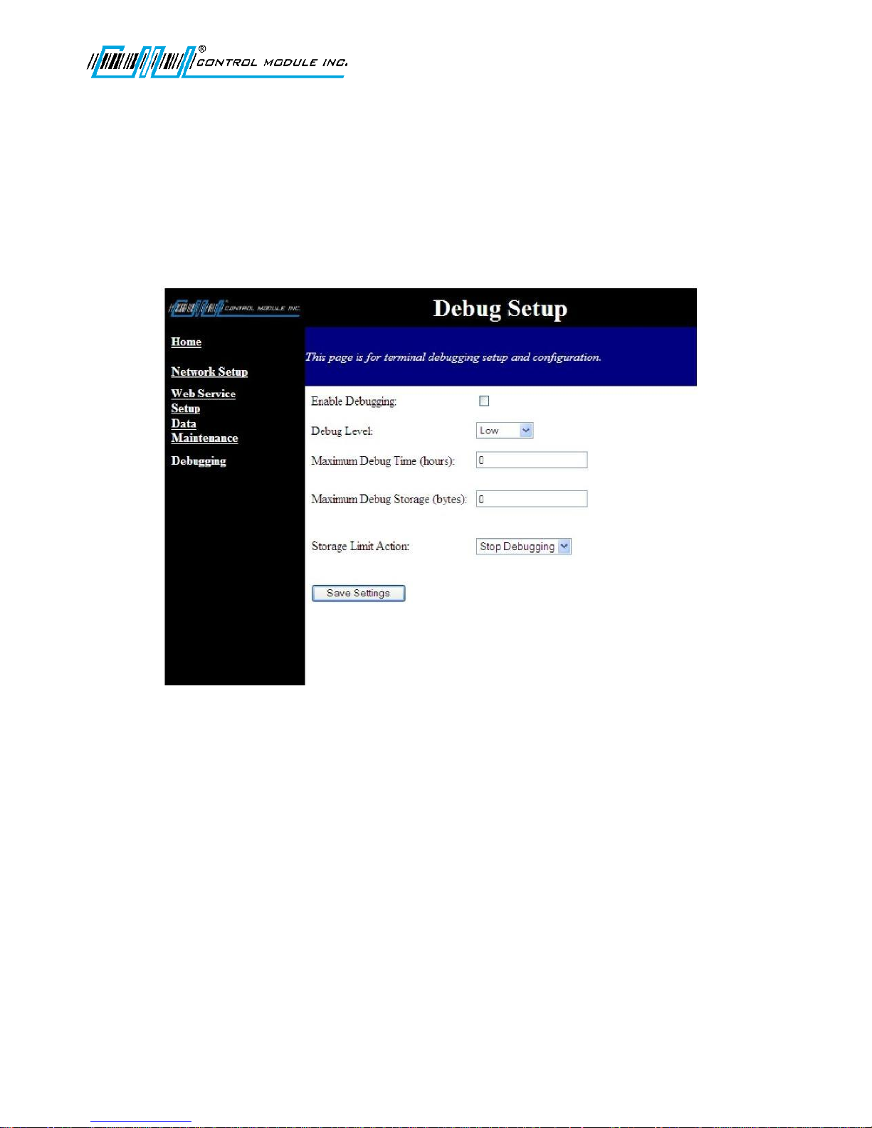
Debugging
The Debug Setup page allows an administrator to enable application and system debugging. Configurable
options:
Enable/disable debugging • Max Debug Storage (bytes)
Debug Level • Storage Limit Action
Max Debug Time (hours)
Note: The default location for the debug file is \ramdisk\errors.txt
Debug Level
This setting defines the minimum level of messages that will be logged. This only affects terminal applications
that utilize the debug levels. Debug messages without levels are always stored. The debug priority levels
include (Low, Medium, High, Severe) to write to the file.
Maximum Debug Time
This Sets up the maximum amount of time in hours (x number of hours) to allow debugging to run. When the
time is reached debugging is stopped. If set to zero (0 = infinite). If the Terminal is rebooted at any time the
debugging will stop.
Revision C November 2016 47
Page 48

Genus G1 MARK II User Manual
UM3010-2
Maximum Debug Storage
Specify the max size of the debug file in bytes at which point the action taken is determined by Storage Limit
Action. If set to zero it will continue to write until the ‘\ramdisk’ of the Terminal is full.
Storage Limit Action
Determines whether to Overwrite or to Stop Debugging when the Maximum Storage Bytes value has been
reached.
Overwrite is the preferred setting as it will let error logging run continuously while still limiting the space used to
the size of Maximum Debug Storage by overwriting the oldest messages with new information.
Errors.txt - The errors.txt file is a general repository for informational, warning, and critical messages useful for
troubleshooting the operation of the terminal, or the transfer of data from the terminal to the host.
The Genus 1 terminal logs informational messages on startup to the errors.txt file. Some messages
are dependent on the optional hardware provided with the terminal.
Sample startup messages:
********************************************************
Fri Nov 17 13:46:42 CST 2017
Genus file version:341-001 V4.04.33
Toolkit API(classes.jar):F299-1.0.161
DEBUG_LEVEL:0 DEBUG_SIZE:50000 LIMIT_ACTION:true
********************************************************
[13:46:43:350]CMInit:initSystem()
[13:46:43:420]CMInit:initSystem():CMEventLog.getInstance()
[13:46:44:175]CMInit:initSystem():TAdminConfig.getInstance()
[13:46:45:175]WEBSERVER_PORT:80
[13:46:45:85]NanoHTTPD: Starting HTTP Web Server Listener on Port 80...
[13:46:46:500]NanoHTTPD: HTTP Web Server Listener Started on Port 80!
[13:46:48:405]CMTaskScheduler::addTask(clearSessions) - scheduled:Fri Nov 17
23:59:00 CST 2017 Thread:main
[13:46:48:485]Initializing MaxSocketRecvTm - 30000
[13:46:48:550]CMInit:run()
[13:46:48:640]About to query H8
[13:46:48:760]NTSD value from user file: NTSD=0
[13:46:48:850][1]h0PS00354D@1000
[13:46:49:300]CMInit:run():recalled OEM Config
[13:46:49:350]INIT System status event:PS00354D
[13:46:50:140]CMInit:run():AppName:com.controlmod.demo.App
[13:46:50:595]CMStatus Event: prog PS00354D
[13:46:50:660]CMStatus Event: diagnostic 0
[13:46:50:725]CMStatus Event: config 0
[13:46:51:200]CMStatus Event: run 0
[13:46:51:265]CMStatus Event: opt1 @
[13:46:51:330]CMStatus Event: opt2 1
[13:46:51:395]H8 Revision: D
[13:46:51:460]OK to enable Suprema auto reset command
[13:46:52:50]enableH8AutoReset(true)
[13:46:59:325]Application version: DemoApp 0.2.3 2017-10-09
[13:46:59:395]App Starting
Revision C November 2016 48
Page 49
Troubleshooting Terminal Issues
Terminal Issue
Possible Causes
Resolution
Terminal does not power on
No Power to the terminal.
Verify power cable is connected to
terminal. If a UPS is included verify
power is connected to the UPS and
the power cable from the UPS is
connected to the Terminal.
Contact your service technician or
electrical contractor.
Loader screen does not display;
only the copyright screen then it
goes blank.
Loader is missing or has become
corrupt.
Refer to the Service and Technical
Support section in this document.
Default loads all the time after
Loader
Genus executable has become
corrupt or needs to be
programmed.
Reload Genus to the terminal.
Refer to Steps to Re-Program
Genus Firmware section in this
document.
Terminal stops at
Initializing Network
Terminal is searching for DHCP
and/or Network connection is not
available.
Wait at least three minutes. Make
sure your network cable and
switch are connected and working
properly.
Terminal displays Serial
Loader Mode
Terminal does not have a usable
copy of Genus or Default.
Refer to the Service and Technical
Support section in this document.
Terminal displays Error
Initializing RTC
The Real Time Clock is not
functioning.
Refer to the Service and Technical
Support section in this document.
Terminal displays Error
Opening Classes.jar
Terminal does not have the Classes
(or API) loaded.
Reload Classes to the terminal.
Refer to Steps to Re-Program
Genus Firmware section in this
document.
Terminal displays Error
Opening App.jar
Terminal does not have the App.jar
application loaded.
Load App.jar to the terminal. Refer
to Loading a Customer-Defined
Java Application section in this
document.
Terminal displays Error
Initializing RAM File
System
The SRAM on the memory board is
failing.
Refer to the Service and Technical
Support section in this document.
Genus G1 MARK II User Manual
UM3010-2
Revision C November 2016 49
Page 50

Troubleshooting Genus WiFi
Issue
Resolution
The WiFi Module cannot find
the Access Point.
The AP (Access Point) cannot
find the WiFi Module.
The WiFi Module cannot
associate with an Access
Point.
The Genus terminal cannot
access the WiFi Module for
setup purposes
The Genus terminal still
cannot access the WiFi
Module after “fallback” has
occurred.
Troubleshooting Suggestions Table
Verify that the Link LED is solid green. If it isn’t, refer to “LED
Troubleshooting” table.
Click the Refresh button in your Access Point’s configuration application.
If the problem remains, check the WiFi Module’s physical connections.
Then power-down the WiFi Module, power it up, and check the LED
status. The “WiFi LED Description” table defines the various LED status
indications. Make sure that there is not another AP in the area that may
be interfering with your AP.
If the problem remains, contact CMI.
Change the location of the WiFi Module to improve reception. If that
does not help, go into the WiFi configuration and be sure the SSID
matches that of the Access Point (remember the SSID is case sensitive).
Also verify that the security settings such as WEP keys or WPA
PASSPHRASE match the AP exactly.
Genus G1 MARK II User Manual
UM3010-2
Most likely the Terminal does not know the IP address of the WiFi
Module. This will happen if the Module is set for DHCP and the Module
obtains an IP from the server. The Terminal will be able to access the
Module by using the WiFi Module’s fallback IP address. The WiFi
Module will revert back to the fallback Ethernet settings after 60
seconds if it is moved out of range of the AP or if the AP is powered
down. Fallback mode is indicated when the Power LED changes from
amber to green and the Link LED is blinking red.
Default Fallback Ethernet Settings
IP address: 192.168.0.68
Subnet Mask: 255.255.255.0
Gateway IP: 0.0.0.0
DHCP must be turned off in the Genus terminal and fixed address
settings entered that match the above values. The first three octets of
the Terminal must match the address above. The last octet must be
something other than 68.
The fallback Ethernet settings have been changed to something other
than the default values. The default values can be restored to the WiFi
Module by turning the Module on while holding the reset button
momentarily. All user changed values will be defaulted.
Revision C November 2016 50
Page 51

Genus G1 MARK II User Manual
If the...
Perform These Tasks...
Link LED continues to Blink Red.
WiFi Module has not found an Access Point with which to associate. Be
sure the Access Point you want to use is turned on and has WEP disabled
(you can enable WEP after the WiFi Module has been configured).
If this does not help, be sure there are no nearby devices causing
interference. If there are, either turn off or move the device causing the
interference or move the WiFi Module and Access Point to another
location.
Comm LED is Red and Link LED is
Green but you are unable to pass
data.
Check the Ethernet settings of the Genus terminal. Except for the last octet
of the IP address, all settings should match those of the WiFi Module. If the
Terminal is set for DHCP, your network must have a DHCP server available
when the Genus Terminal is powered-up.
UM3010-2
Indicator LED Troubleshooting Table
Power LED does not turn
On.
Power LED turns Red. Remove power and re-apply. If the Power LED remains Red, contact CMI.
Power LED is Amber. WiFi Module has not established an IP address either through
DHCP or Static methods.
Enable your DHCP server and re-start the Module.
Check power connector is properly inserted. Contact your service
technician.
If DHCP is enabled, your network must have a DHCP server available when
the WiFi Module is powered-up. Most AP/Routers have a DHCP server
built-in.
Comm LED is Off or Amber. Be sure the Genus terminal is connected to the WiFi Module and that the
device is turned on.
Revision C November 2016 51
Page 52
Genus G1 MARK II User Manual
LED
LED
Color
Function
Comm
Off
No power, or no WiFi configuration session is established and
no Ethernet physical connection is detected.
Red
No WiFi configuration session is established; an Ethernet
physical connection is detected.
Blinking Red
An Ethernet physical connection was detected and there is
Ethernet traffic present on that connection, but no WiFi
Amber
A WiFi configuration session is established but no physical
Ethernet connection is detected (i.e., no Ethernet cable is
Blinking
Amber
A WiFi configuration session is established, a physical Ethernet
connection is detected, and the Module is transmitting or
receiving data across the wired Ethernet port.
Green
A WiFi configuration session is established, a physical Ethernet
connection is detected, but there is no active data movement
Link
Off
Module is not receiving power.
Blinking Red
Module is searching for an Access Point.
Green
Wireless network and MAC have associated with an Access
Point.
Power
Off
Module is not receiving power.
Red
Module failed its Power On Self Test (POST) and is not
configured for wireless communication.
Amber
Module passed its POST but is not configured for wireless
communication.
Green
Module passed its POST and is configured for wireless
communication.
UM3010-2
WiFi LED Description
Revision C November 2016 52
Page 53

Genus G1 MARK II User Manual
UM3010-2
Reference
Note: All command in this chapter are case-sensitive.
Steps to Re-Program Genus Firmware:
In the event an update becomes available for the Genus terminal, the firmware can be updated in the field.
The following items are required to (re-)program Genus firmware:
Data terminal to be programmed, connected to the network
The IP address of the Genus terminal
The computer / laptop connected to the network and able to PING the data terminal
Genus firmware
Genus (“System”) file update:
The Genus terminal application makes use of CMI Java classes and interfaces in the CMI Genus API.
tftp –i <ip address> PUT Genus \flashdisk\Genus
Note: Genus file name may be versioned (e.g. g2_3_3_12)
Classes (API) update:
The classes file is specific to your terminal type (G1 or G2). Check the release notes or other documentation
provided with the updated files to confirm the name of Classes.jar (may be GI.jar or GII.jar).
tftp –i <ip address> PUT Classes.jar \flashdisk\Classes.jar
Note: The terminal will reboot after replacing the Genus or Classes files Wait until the terminal reboots before
sending additional files.
Confirming Updates:
To confirm that the Genus and/or Classes update(s) took place, follow the steps below:
1. Place the terminal in Offline mode
2. Locate the “Terminal Information” screen
3. Check “API:” to find Classes version.
4. Scroll to “Program Version:” to locate Genus Version.
Revision C November 2016 53
Page 54
Genus G1 MARK II User Manual
Loader G1
Control Module Inc.
Program: xxx-xxx
VX.XX.XX
Loader Setup
Press E to Continue
other key to Exit
Enter IP ADDRESS:
192.168.000.064
Enter SUBNET MASK:
255.255.255.000
Enter GATEWAY:
000.000.000.000
SETTINGS SAVED
Force Default?
<F1=Yes><C=No>
Loading Default
Default
Control Module Inc.
Program: xxx-xxx
VX.XX.XX
UM3010-2
Loading A Customer Defined Java Application
This application runs on the terminal and handles both a user interface and any backend processing or
communication. This is created by the user of the terminal, a value added Reseller, or CMI.
tftp -i <ip address> PUT <myapp.jar> \flashdisk\App.jar
where <myapp.jar> is the local name of the user created Java application.
Note: The terminal will reboot after sending the file above.
See the Genus Software Development Kit (SDK) for more information on creating terminal applications.
Loader Mode
This application is available as of version V2.02.04 of the Genus Terminal firmware and provides access to
terminal network settings when communication to the Terminal has been compromised.
To access the Loader Mode put the Terminal into offline mode by using the on line/off line setup switch on the
back of the terminal.
Press E to quickly to enter the Loader Mode when the Loader Setup screen appears.
The Terminal retains the IP address that was stored and will display this in Loader Mode. If DHCP had been set
the IP address would advance and return between octets. Pressing C will zero out the octets. User 0-9 or the right
and left arrow keys to display as all zeros in the octets.
Press E to advance to the next network setting. Enter the subnet mask and gateway settings. Press E to save all
the settings.
Press F1 to force the default to load.
If the server cannot be found, the terminal will display the Server Not Found message, followed by the
prompt to enter a new TFTP server IP.
Revision C November 2016 54
Page 55

Genus G1 MARK II User Manual
UM3010-2
Calculating Number of Transactions That Can Be Stored
The number of transactions that can be stored is determined by the size of the transaction. Each transaction
minimally has 45 bytes as header data and has up to 4KB of transaction data.
A transaction looks as follows:
[45 Bytes – Header] [Up to 4KB Data]
To calculate the number of transactions that can be stored, you can use the following calculation:
1,048,576 / (45 + <data length> )
For example, if you were simply using 10-digit badges, the calculation would appear as follows:
1,048,576 / (45 + 10) = 19065
Revision C November 2016 55
Page 56
Genus G1 MARK II User Manual
UM3010-2
Telnet Session
A Telnet session can be established with the Genus Terminals. Once established the general network parameters
are available to update. Be sure to use Port 9999. For example: 192.168.1.5.9999
Selection 2 below: The Change Application Status, applies to the user-generated application program running on
the Genus Terminal.
Selection 6 below: The Maintenance option requires a password. Contact CMI Technical Support before choosing
this option.
Options 7-9 are straight forward as listed in the Telnet menu selections.
Revision C November 2016 56
Page 57

Genus G1 MARK II User Manual
UM3010-2
Programming Table (Code 39)
This table provides Code 39 barcode access to special characters that are not available on the Genus terminal
keypad. By using a digital barcode wand, these individual characters can be entered into the network setup
parameters prompted by the Terminal. The barcodes are identified on the next page.
*0* *1* *2* *3* *4*
*5* *6* *7* *8* *9*
*A* *B* *C* *D* *E*
*F* *G* *H* *I* *J*
*K* *L* *M* *N* *O*
*P* *Q* *R* *S* *T*
*U* *V* *W* *X* *Y*
* Z *
*a* *b* *y* *ö* *e*
*f* *g* *h* *i* *j*
*k* *l* *m* *n* *o*
*p* *q* *p* *s* *t*
*u* *v* *w* *x* *y*
*z*
Revision C November 2016 57
Page 58

Genus G1 MARK II User Manual
UM3010-2
*0* *1* *2* *3* *4*
*5* *6* *7* *8* *9*
*A* *B* *C* *D* *E*
*F* *G* *H* *I* *J*
*K* *L* *M* *N* *O*
*P* *Q* *R* *S* *T*
*U* *V* *W* *X* *Y*
* Z *
*a* *b* *y* *ö* *e*
*f* *g* *h* *i* *j*
*k* *l* *m* *n* *o*
*p* *q* *p* *s* *t*
*u* *v* *w* *x* *y*
* z *
Revision C November 2016 58
Page 59

*! * *" * *#* *$ * *% *
*−*
*@
*[* *\* *]*
*¢* *{* *|*
~
_
*
−
*
*@
*[* *\* *]*
*¢* *{* *|*
~
_
*& * * ' * *( * * ) * *¥ *
*+* *,* *.* */* *:*
*;* *<* *=* *>* *?*
*}* *£*
Space
Genus G1 MARK II User Manual
UM3010-2
K e y t o a b o v e b a r c o d e s :
*!* *"* *#* *$* *%*
*& * *'* *( * *) * *¥*
*+* *,* *.* */* *:*
*;* *<* *=* *>* *?*
`
*}* *£*
Space
Revision C November 2016 59
Page 60

Genus G1 MARK II User Manual
UM3010-2
Service & Technical Support
RMA Policy
Return Material Authorization (RMA) Procedure: The CMI Service Center assigns an RMA number for all products
returned for service. If you have a product that requires service, please contact the CMI Service Center at 1-800527-4998 or 860-253-4218.
The CMI Service Center provides various service options:
Maintenance – Annual (five day in-house turnaround)
Time & Material – Three options (two, five and 10 day turnaround)
The following information is required to process the return:
Model and serial number of product
Brief description of problem
Name and telephone number of technical contact
Customer’s return address
Customer’s billing address
After an RMA# is issued, please return the product to the address below in a shock-proof package to the CMI
Service Center. Please ensure the RMA# is clearly marked on the outside of the package and ship to:
CMI Service Center
89 Phoenix Avenue
Enfield, CT 06082
Attn: RMA# _____________
Returned products cannot be processed without an RMA number.
Technical Support
CMI’s Technical Support Number: 888-753-8222 can be reached during the following hours of operation:
M-F, 8:00 A.M. – 4:30 P.M. EST, excluding holidays.
Standard Terms and Conditions of Sale
For Standard Terms and Conditions, and Warranty information:
http://controlmod.com/technical-support/order-terms/
Revision C November 2016 60
 Loading...