

Page 1
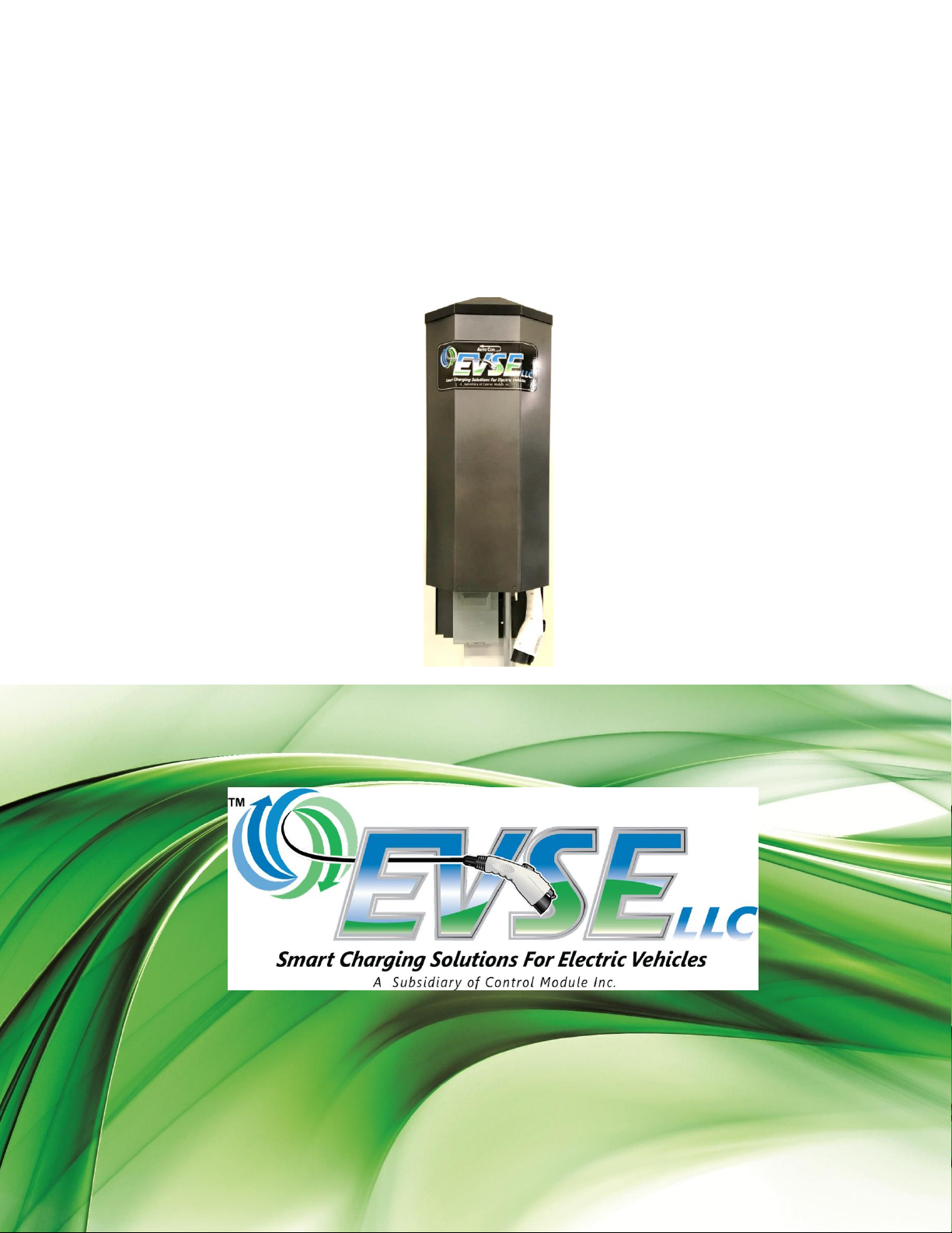
Installation and User Manual
Model 3704
Electric Vehicle Supply Equipment (EVSE)
Patents Pending
3704-IG-A04xx Rev 1.0
February 2019
Electric Vehicle Supply Equipment (EVSE)
Model 3704 Family
For Utility Pole-Mounted Installations
Control Module Inc., EVSE LLC
State of the Art EVSE
3704-IG-A04xx Installation and User Manual May 20, 2019 Page I
Page 2

Table of Contents
IMPORTANT NOTES ....................................................................................................................................................................... III
SAFETY AND COMPLIANCE ......................................................................................................................................................................... III
LIMITATION OF LIABILITY ........................................................................................................................................................................... III
FCC COMPLIANCE STATEMENT ................................................................................................................................................................... III
IMPORTANT ............................................................................................................................................................................................ III
EXPOSURE TO RADIO FREQUENCY ENERGY .................................................................................................................................................... III
NO ACCURACY GUARANTEE ....................................................................................................................................................................... III
U.S. PATENT NUMBERS: ........................................................................................................................................................................... III
COPYRIGHT AND TRADEMARKS: .................................................................................................................................................................. IV
INSTRUCTIONS PERTAINING TO RISK OF FIRE OR ELECTRICAL SHOCK ............................................................................................. V
IMPORTANT SAFETY INSTRUCTIONS .............................................................................................................................................................. V
INSTRUCTIONS DE SECURITE IMPORTANTES ................................................................................................................................................... VI
INTRODUCTION TO MODEL 3704-A00XX EVSE UNIT ........................................................................................................................ 1
SAFETY FEATURES ..................................................................................................................................................................................... 1
COMMUNICATION OPTIONS ........................................................................................................................................................................ 1
ADDITIONAL OPTIONS ................................................................................................................................................................................ 2
SPECIFICATIONS ........................................................................................................................................................................................ 3
SITE PREPARATION .......................................................................................................................................................................... 4
DIMENSIONS ............................................................................................................................................................................................ 4
2010 ADA STANDARDS FOR ACCESSIBLE DESIGN ........................................................................................................................................... 5
ELECTRICAL SERVICE CONNECTIONS .............................................................................................................................................................. 7
MOUNTING THE MODEL 3704 ......................................................................................................................................................... 9
REMOVING THE COVER .............................................................................................................................................................................. 9
HANGING THE 3704 EVSE ........................................................................................................................................................................ 9
WIRING THE EVSE FOR POWER ...................................................................................................................................................... 10
CONFIGURING J1772 CABLE OPERATION ....................................................................................................................................... 11
TESTING BASIC CABLE OPERATION ............................................................................................................................................................. 11
SETTING THE CABLE LOWERING HEIGHT FOR ADA ......................................................................................................................................... 12
REPLACING THE COVER .................................................................................................................................................................. 13
INSTALLATION NOTES .................................................................................................................................................................... 14
DIP SWITCH SETTINGS ................................................................................................................................................................... 15
OPERATION ................................................................................................................................................................................... 16
TESTING AND FAULT MODES ......................................................................................................................................................... 17
STATUS INDICATOR CHART ........................................................................................................................................................................ 18
USER MAINTENANCE ..................................................................................................................................................................... 19
MOVING, TRANSPORTING, AND STORAGE .................................................................................................................................................... 19
CUSTOMER SUPPORT .................................................................................................................................................................... 20
WARRANTY.................................................................................................................................................................................... 21
3704-IG-A04xx Installation and User Manual Page II
Page 3

Important Notes
Safety and Compliance
This document provides instructions for installing the Charging Station Model 3704 Series. Before installation of the Charging
Station by licensed professionals, you should review this manual carefully and consult with a licensed contractor, licensed
electrician and trained installation personnel to ensure compliance with local building practices, climate conditions, safety
standards, and state and local codes.
The Charging Station should be inspected by a qualified installer prior to the initial use. Under no circumstances will
compliance with the information in this manual relieve the user of responsibility to comply with all applicable codes or safety
standards. This document describes the most commonly-used installation and mounting scenarios. If situations arise in which
it is not possible to perform an installation following the procedures provided in this document, contact Control Module Inc.,
EVSE LLC. Control Module Inc., EVSE LLC, is not responsible for any damages that may occur resulting from custom
installations that are not described in this document.
Limitation of Liability
In no event shall Control Module Inc., EVSE LLC, or its authorized distributors be liable for any indirect, incidental, special,
punitive, or consequential damages, including without limitation, lost profits, lost data, loss of use, cost of cover, or loss or
damage to the Watt Point Charging Station, arising out of or relating to the use or inability to use this manual, even if Control
Module Inc., EVSE LLC, or its authorized distributors have been advised of the possibility of such damages.
FCC Compliance Statement
This equipment has been tested and found to comply with the limits for a Class A digital device, pursuant to part 15 of the
FCC Rules. These limits are designed to provide reasonable protection against harmful interference when the equipment is
operated in a commercial environment. This equipment generates, uses, and can radiate radio frequency energy and, if not
installed and used in accordance with the instruction manual, may cause harmful interference to radio communications.
Operation of this equipment in a residential area is likely to cause harmful interference in which case the user will be
required to correct the interference at their own expense.
Important
Changes or modifications to this product not authorized by Control Module, Inc., EVSE LLC, could affect the EMC compliance
and revoke your authority to operate this product.
Exposure to Radio Frequency Energy
The radiated power output of the ZigBee® radio (optional) in this device is below the FCC radio frequency exposure limits for
uncontrolled equipment. This device should be operated with a minimum distance of at least 7.8 inches (20 cm) between the
ZigBee antenna and a person’s body, and must not be co-located with any other antenna or transmitter by the manufacturer,
subject to the conditions of the FCC Grant.
No Accuracy Guarantee
Reasonable effort was made to ensure that the specifications and other information contained in this manual are accurate
and complete at the time of publication. The specifications and other information in this manual, however, are subject to
change at any time and without prior notice.
U.S. Patent Numbers:
Patents Pending
3704-IG-A04xx Installation and User Manual Page III
Page 4

Copyright and Trademarks:
Copyright 2014-2019 Control Module Inc., EVSE LLC. All rights reserved. This material is protected by the copyright laws of
the United States and other countries. It may not be modified, reproduced or distributed without the prior, express written
consent of Control Module Inc., EVSE LLC.
The EVSE LLC logo is the trademark of Control Module Industries, Inc.
ZigBee is a registered trademark of the ZigBee Alliance.
3704-IG-A04xx Installation and User Manual Page IV
Page 5
Instructions Pertaining To Risk of Fire or Electrical Shock
The following is a summary of safety concerns relevant to the installation and use of the Model 3704 EVSE Unit. Failure to
follow these safety instructions may lead to serious injury, death and/or damage to the equipment.
WARNING: is used to provide a warning of hazardous voltage and possibility of electric shock.
CAUTION: is used to provide awareness of important safety information in these instructions.
Important Safety Instructions
WARNING: Only qualified personnel should perform the installation. This installation must be performed in
accordance with all local electrical/building codes and ordinances. Follow lockout/tagout
procedures.
Improper connection of the equipment grounding conductor may result in a risk of electric shock.
Reference National Electrical Code, ANSI/NFPA 70 for proper sizing of the ground conductor.
Do not use this product if the flexible power code or EV cable are frayed, have broken insulation, or
show any signs of damage.
CAUTION: This device is intended to be used to charge vehicles that do not require ventilation during charging.
To reduce the risk of fire, connect only to a dedicated circuit with 40A maximum branch circuit over–
current protection in accordance with the National Electrical Code, ANSI/NFPA 70.
(For Zigbee equipped units)
To satisfy FCC RF exposure requirements for mobile transmitting devices, a separation distance of 7.8
inches (20 cm) or more should be maintained between the antenna of this device and persons during
device operation. To ensure compliance, operations at closer than this distance is not
recommended. The antenna used for this transmitter must not be co-located in conjunction with
any other antenna or transmitter.
Additional considerations which will contribute to safe operation of this unit include the following:
DO:
Read all instructions before using this product.
The device should be supervised when used around children.
In case of a problem, contact your installer or CMI Customer Support.
DON’T:
Put fingers into the electric vehicle connector.
Use this product if the enclosure or the EV connectors are broken, cracked, open or show any other indication
of damage.
Attempt to repair or service the unit yourself.
SAVE THESE INSTRUCTIONS
3704-IG-A04xx Installation and User Manual Page V
Page 6
Instructions De Sécurité Importantes
AVERTISSEMENT: sert à fournir une alerte de tensions dangereuses et possibilité de choc électrique.
ATTENTION : est utilisé pour fournir la sensibilisation des renseignements importants dans ces instructions.
INSTRUCTIONS DE SÉCURITÉ IMPORTANTES
AVERTISSEMENT: Seul le personnel qualifié doit effectuer l'installation. Cette installation doit être effectuée
conformément à tous les codes électrique/bâtiment locaux et ordonnances. Suivre les
procédures de verrouillage/verrouillage.
Connexion inadéquate de l'équipement échouement du chef d'orchestre peut entraîner un
risque de choc électrique. Code National de l'électricité, ANSI/NFPA 70 pour le
dimensionnement bon chef d'orchestre au sol de référence.
Ne pas utiliser ce produit si le code de la puissance souple ou l'EV sont effiloché de câble, ont
brisé isolant ou présentent pas de signes de dommages.
ATTENTION: Ce dispositif est destiné à être utilisé pour charger les véhicules qui ne nécessitent pas de ventilation
pendant la recharge.
Afin de réduire le risque d'incendie, se connecter uniquement à un circuit dédié avec 40 a maximum
des branches circuit over–current protection conformément aux dispositions du Code électrique
National, ANSI/NFPA 70.
(Pour les unités de Zigbee équipé)
Pour satisfaire les exigences de l'exposition du FCC RF pour des périphériques mobiles de
transmission, une distance de séparation de 20 cm ou plus devrait être maintenue entre l'antenne de
ce dispositif et de personnes au cours de l'opération de l'appareil. Afin d'assurer la conformité des
opérations au plus près que cette distance n'est pas recommandée. L'antenne utilisée pour cet
émetteur ne doit pas être colocalisé conjointement avec une autre antenne ou éme.
Voici d'autres considérations qui contribueront à la sécurité de fonctionnement de cette unité:
DO:
Lire toutes les instructions avant d'utiliser ce produit.
Le dispositif devrait être supervisé lorsqu'il est utilisé autour des enfants.
En cas de problème, contactez votre installateur ou soutien à la clientèle CMI.
NE PAS:
Mettre les doigts dans le connecteur de véhicule électrique.
Utiliser ce produit si l'enceinte ou les connecteurs EV sont cassées, fissuré, ouvrir ou afficher toute autre indication
de dommages.
Tenter de réparer ou d'un service de l'unité de vous-même.
ENREGISTREZ CES INSTRUCTIONS
3704-IG-A04xx Installation and User Manual Page VI
Page 7

Introduction to Model 3704-A04XX EVSE Unit
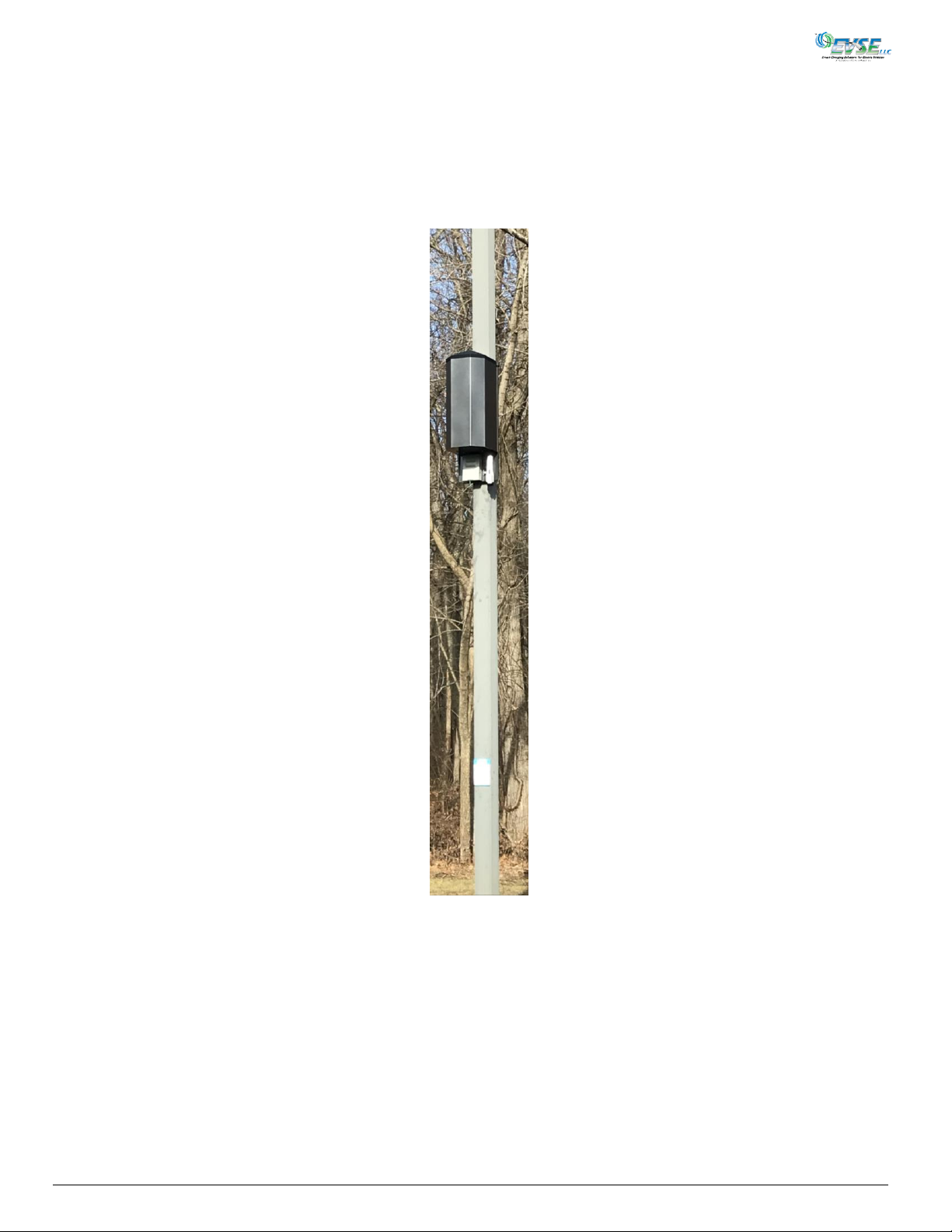
The Model 3704 Electric Vehicle Supply Equipment (EVSE) is a 7.2 KW pole-mounted EVSE with Auto CoilTM cable
management retraction, capable of providing up to 30A at 208-240VAC, single phase, 50 or 60 Hz. This unit complies with the
SAE J1772 specifications for supplying electrical power to a J1772-compatible Electric Vehicle (EV). The Model 3704
conveniently coils the 25-foot cable internally when not in use. The model 3704 is capable of being controlled remotely to
apply, reduce or disconnect power to the electric vehicle, and can, with an optional EUMD installed, measure both voltage
and current being supplied to the EV. The 3704 can be equipped with an optional internal Gateway Module with a cellularhost connection and an optional Zigbee Module. Five status lights clearly indicate the state of the charging operation.
Safety Features
Tamper Resistent - The J1772 power cord and connector are locked mechanically in the storage position.
Extension - The cable initially lowers to an ADA height, and by pressing the switch on the J1772 connector, the
cable to driven out to the desired length.
Jam Resistent - If you pull the charging cable while it is retracting or if the cable gets caught on anything, cable
retraction will stop. The cable will make one additional attempt to retract. Thereafter, pressing and
releasing the switch on the J1772 connector (Figure 18) will restart the cable retraction process.
Spark Resistent - Electrical power is not applied to the power connector until the J1772 connector is fully inserted into
the power inlet on the Electric Vehicle and communication between the vehicle and charger has been
established. When the switch is pressed on the J1772 connector, voltage is removed.
Shock Resistent - The Model 3704 EVSE is equipped with a Ground Fault Circuit Interrupter (GFCI) which will disconnect
the electrical voltage from the power cord and connector, should current leakage to ground exceed
20 mA. The GFCI circuit is automatically tested at the start of each charge sequence. The GFCI will
attempt three re-closures to see the ground fault cleared before reporting a problem.
Over Current - The Model 3704 EVSE, when in use, continuously monitors the current being delivered to the EV.
Should the current exceed 32A for 15 seconds, the Model 3704 EVSE will disconnect the power to the
EV before the breaker trips. After disconnecting, the 3704 will auto-reset.
Low-Line - The source voltage to the Model 3704 EVSE is continuously monitored while in use. Should the voltage
drop below 180 VAC, the EVSE will disconnect the voltage to the EV to prevent damage to the EV’s
electronic circuits. When the voltage returns to above 200 VAC, the power will be restored to the EV.
Cold Load Start – If power fails while the Model 3704 EVSE is connected and charging an EV, charging will automatically
resume when power is restored. No user intervention is required. The charging will however, be
randomly delayed from 2 to 5 minutes to prevent the power grid from incurring a large power surge.
Plug-Out Detection - The model 3704 EVSE is equipped with a Plug Out Detection circuit that identifies when the connector
is attached to the electric vehicle. This allows the EVSE to immediately remove electric power from the
electric vehicle before the connector is totally removed from the vehicle inlet.
Disconnect Switch - The 5068-050 Mounting Frame, used to mount the 3704, is equipped with a disconnect switch for
locally shutting off power in the event the unit needs to be serviced or inspected.
Communication Options
An optional Gateway Module with a cellular-host connection is installed internally to facilitate two-way communication with
the host network. The 3704 communicates to the internal Gateway directly, or multiple chargers can use Zigbee to talk to
one charger/Gateway. ZigBee networks are secured by 128-bit symmetric encryption keys, so security is assured.
3704-IG-A04xx Installation and User Manual May 20, 2019 Page 1
Page 8
The Gateway Module then connects to an external network via a Cellular modem. The Cellular modem securely transmits
encrypted payment data to and receives authorizations from external PCI-compliant processors. Communication can also link
the EVSE network with third-party network management providers for reporting and call center support.
Additional Options
The Data Router (Figure 8) in the charger can be used in conjunction with a 3790-005 remote RFID reader, and can
accommodate a Fob or club-type card. Operation can also be initiated with an optional QR Code application on a cellphone.
3704-IG-A04xx Installation and User Manual Page 2
Page 9

Specifications
Product Code
Product Code
3704-A04XX
Electrical*
Voltage
Current (Rated)
Current (Simulated Level 1)
208-240 VAC
30A/16A Switchable by Dip Settings
7A@208-240 VAC (On Command)
Connections
Line 1 and 2, Ground
Stand By Power
Power Output
Less than 10W typical
7.2kW
Safety Features
Over Current Disconnect
32A/18A Switchable by Dip Settings
Surge Protection
6KV @ 3000A
Ground Fault
Internal 20 mA CCID with auto re-closure (three attempts)
Compliance
Safety
IEC/UL/CSA C22.2 61010-1, UL2594, UL2231-1, UL2231-2, NEC Article 625, SAE J1772
EMC
FCC Part 15 Class A, Canadian ICES-003
ZigBee (Charger to Charger)
Cellular (Host)
FCC ID: MCQ-PS2CTH, IC: 1846A-PS2CTH
FCC ID: RI7LE910NAV2, IC: 5131A-LE910NAV2
Environmental
Operating Temperature
-22° to 122° F (-30° C to 50° C) ambient
Operating Humidity
Up to 95% non-condensing
NEMA Rating
NEMA 3R
General
Dimensions
28.50 in (h) x 12.64 in (w) x 12.25 in (d)
Weight
Mounting
33 lbs.
Use 5068-050 Mounting Frame
*Observe all required Lockout/Tagout procedures while making any electrical connections or servicing the unit.
3704-IG-A04xx Installation and User Manual Page 3
Page 10
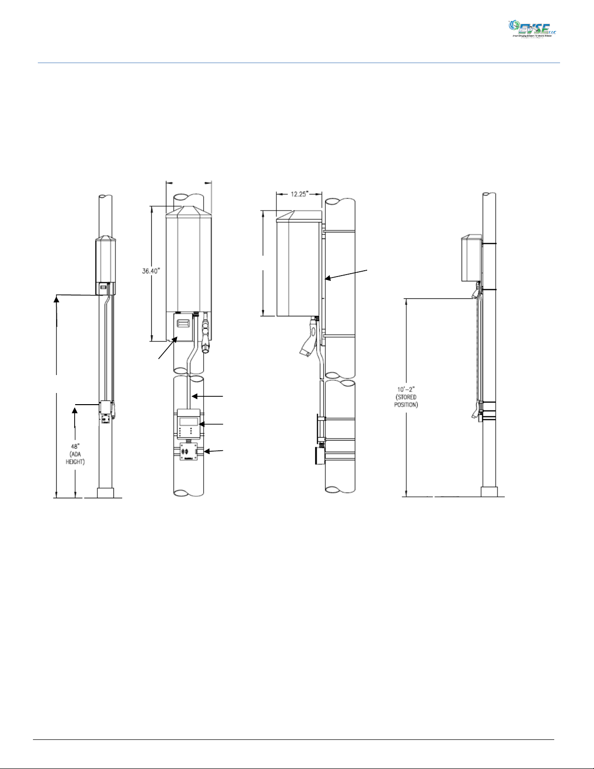
Power
Disconnect
Box Height
5068-050
Mounting
Frame
QR Code
Placard
(Optional)
RFID Card
Reader
(Optional)
Power
Disconnect
Box
RFID Cable
Conduit
12.64”
28.50”
10’2”
Site Preparation
The 5068-050 Mounting Frame must first be installed on the utility pole. Power from the utility pole is wired into the Power
Disconnect Box. Existing wires from the 5068-050 are then connected to the EVSE via the nipple on the top of the Power
Disconnect Box. If the 3704 charger will not be installed right away, the top nipple should be sealed to prevent water
(rain/snow) from entering the Disconnect Box. If an optional RFID Reader is being installed, conduit needs to be run from the
Reader to the Reader Access Tab on the bottom of the 5068-050.
Dimensions
3704-IG-A04xx Installation and User Manual Page 4
Figure 1
Page 11
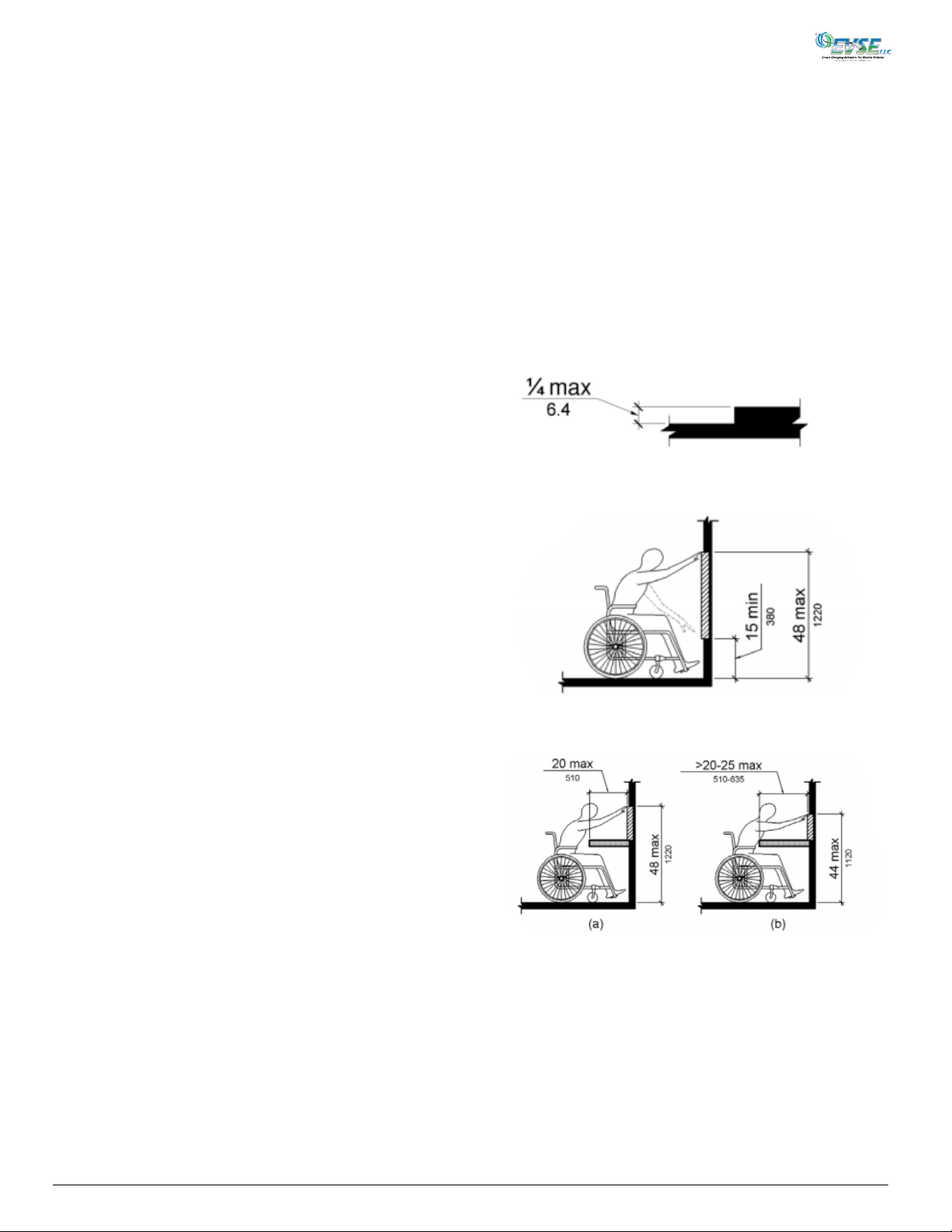
303.2 Changes in Level – Vertical
Changes in level of ¼ inch (6.4 mm) high maximum shall be
permitted to the vertical.
Figure 2A
308.2.1 Forward Reach – Unobstructed
Where a forward reach is unobstructed, the high forward
reach shall be 48 inches (1220 mm) maximum and low
forward reach shall be 15 inches (380 mm) minimum above
the finish floor or ground.
Figure 2B
308.2.2 Forward Reach – Obstructed High Reach
Where a high forward reach is over an obstruction, the
clear floor space shall extend beneath the element for a
distance not less than the required reach depth over the
obstruction. The high forward reach shall be 48 inches
(1220 mm) maximum where the reach depth is 20 inches
(510 mm). Where the reach depth exceeds 20 inches (510
mm), the high forward reach shall be 44 inches (1120 mm)
maximum and the reach depth shall be 25 inches (635 mm)
maximum.
Figure 2C
2010 ADA Standards for Accessible Design
According to the 2010 Americans With Disabilities Standards for Accessible Design, “Each facility or part of a facility
constructed by, on behalf of, or for the use of a public entity shall be designed and constructed in such manner that the
facility or part of the facility is readily accessible to and usable by individuals with disabilities, if the construction was
commenced after January 26, 1992.”
While installers should be knowledgeable about all aspects of the requirement, several critical paragraphs and illustrative
figures (Fig. 2A-2E) are referenced below to assist with locating the EVSE to meet reach and obstruction requirements of the
Act. When properly located relative to the curb, the Model 3704 is compliant with all aspects of the following ADA
paragraphs.
3704-IG-A04xx Installation and User Manual Page 5
Page 12
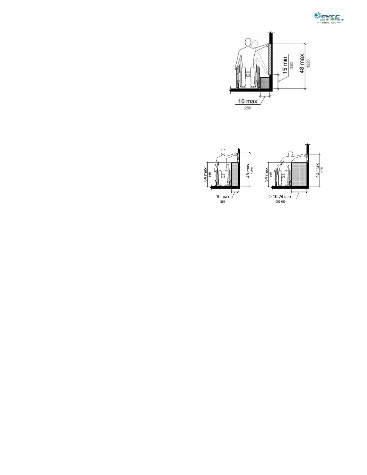
308.3.1 Side Reach – Unobstructed
Where a clear floor or ground space allows a parallel
approach to an element and the side reach is
unobstructed, the high side reach shall be 48 inches (1220
mm) maximum and the low side reach shall be 15 inches
(380 mm) minimum above the finish floor or ground.
Figure 2D
308.3.2 Side Reach – Obstructed High Reach
Where a clear floor or ground space allows a parallel
approach to an element and the high side reach is over an
obstruction, the height of the obstruction shall be 34
inches (865 mm) maximum and the depth of the
obstruction shall be 24 inches (610 mm) maximum. The
high side reach shall be 48 inches (1220 mm) maximum for
a reach depth of 10 inches (255 mm) maximum. Where
the reach depth exceeds 10 inches (255 mm), the high side
reach shall be 46 inches (1170 mm) maximum for a reach
depth of 24 inches (610 mm) maximum.
Figure 2E
309 Operable Parts
309.1 General – Operable parts shall comply with 309.
309.2 Clear Floor Space – A clear floor space or ground
space complying with 305 shall be provided.
309.3 Height – Operable parts shall be placed within one or
more of the reach ranges specified in 308.
309.4 Operation – Operable parts shall be operable with
one hand and shall not require tight grasping, pinching, or
twisting of the wrist. The force required to activate
operable parts shall be 5 pounds maximum.
NOTE: In order to remain ADA-compliant, from the user’s perspective, the 3704’s QR Code on the QR Code Reader Placard
or the Proximity Reader MUST be no more than 48 inches from the ground when mounted to the pole (Figure 1).
3704-IG-A04xx Installation and User Manual Page 6
Page 13
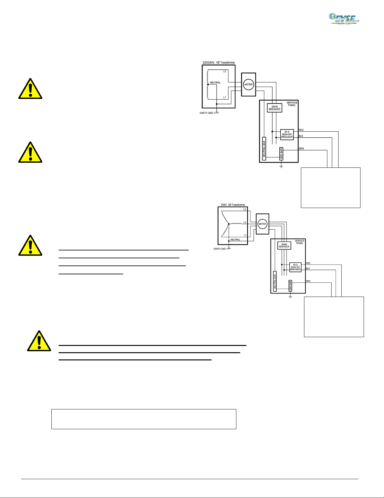
Caution:
The two phases used must
each measure 120V to
Neutral. Earth Ground must
be connected to Neutral at
only one point, usually at the
Service Entry Breaker Panel.
Caution:
This EVSE is a single-phase device. Do not
connect all 3 phases of a 3-phase feed!!!
You may use any two phases of a 3-phase,
Wye-connected feed ! The center-point of the
3 phases (usually used as Neutral) must be
grounded somewhere in the system. A currentcarrying Neutral is not needed by the EVSE.
The two phases used must each measure 120V
to Neutral.
1) 220/240 VAC, Single Phase Transformer:
2) 208 VAC 3-Phase Wye Transformer:
Note: A 40 Amp. Non-GFCI breaker is required for the EVSE.
Model 3722-001
Figure 3A
(See Fig.10)
Attention:
Les deux phases utilisés doivent
chaque 120V mesure au Neutre.
Motif de la terre doit être
connecté au Neutre à un seul
point, habituellement à l'entrée de
Service Breaker Panel.
Attention:
Cette EVSE est un appareil monophasé. Ne pas connecter tous
les 3 phases d'un flux de phase 3!!! Vous pouvez utiliser tout
deux phases d'une phase 3, Wye connecté nourrir ! Le point
central des 3 phases (généralement utilisé comme Neutre) doit
reposer quelque part dans le système. Il n'est pas nécessaire de
Neutre porteurs de courant par le EVSE. Les deux phases utilisés
doivent chaque 120V mesure au Neutre.
Figure 3B
5068-050
Power Disconnect
Box
5068-050
Power Disconnect
Box
Electrical Service Connections
(Observe all required Lockout/Tagout procedures while making any electrical connections, or servicing the Model 3704)
3704-IG-A04xx Installation and User Manual Page 7
Page 14
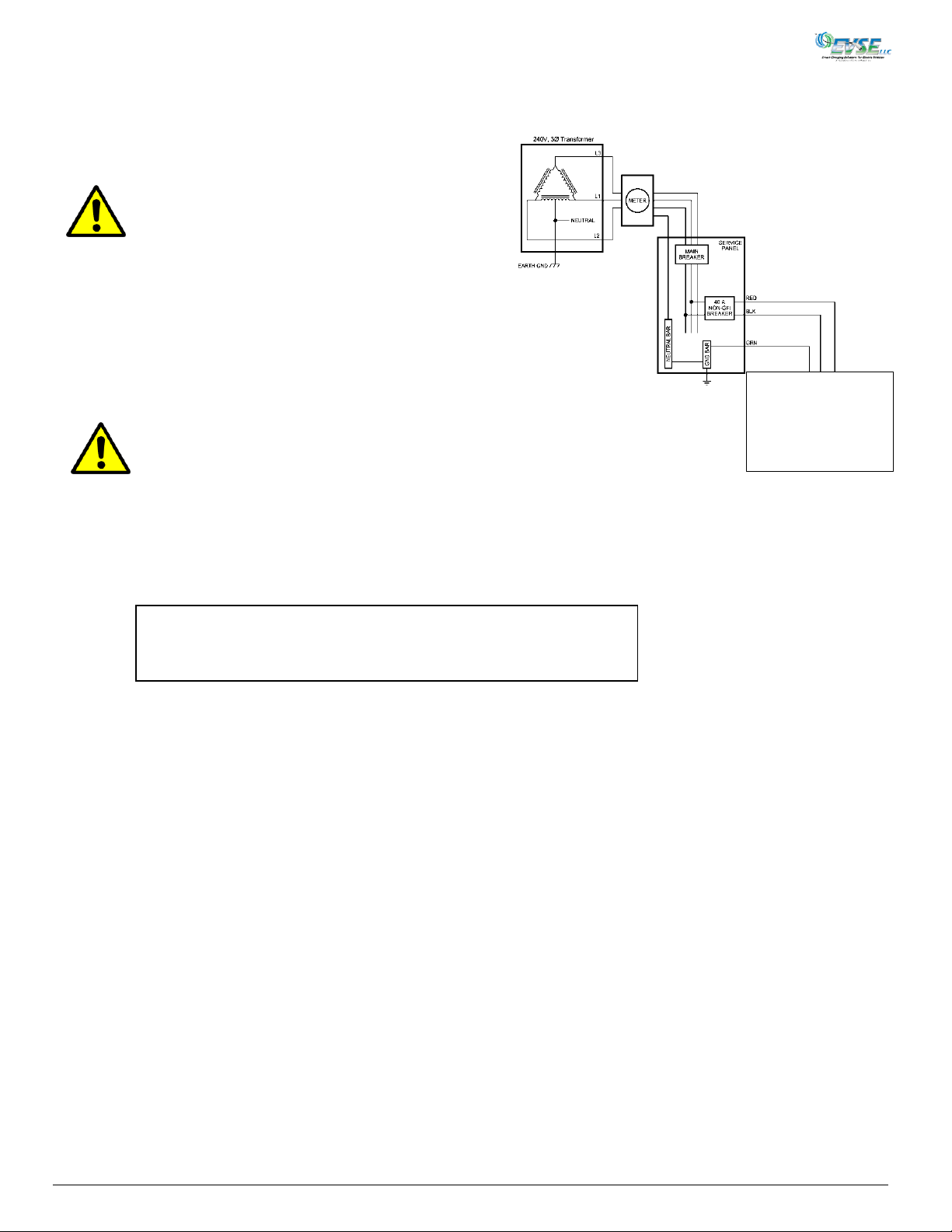
3) 240V Delta Transformer:
Caution:
When using a delta-style power source for
the EVSE, there must be a center tap. Only
the two phases on either side of the center
tap (L1 and L2) can be used and each must
measure 120V to Neutral. If this is not done,
the ground-fault protection will not function
properly. Also, the center tap must be
connected to ground.
Note: A 40 Amp. Non-GFCI breaker is required for the EVSE.
Figure 3C
Attention:
Lorsque vous utilisez une source d'alimentation de
delta-style pour la EVSE, il doit y avoir un robinet
center. Seuls les deux phases de chaque côté de
l'eau du robinet center (L1 et L2) peuvent être utilisés
et chacun doit mesurer 120 v au neutre. Si cela n'est
pas fait, la protection du sol-faute ne fonctionnera
pas correctement. Aussi, le robinet du Centre doit
être connecté au sol.
5068-050
Power Disconnect
Box
3704-IG-A04xx Installation and User Manual Page 8
Page 15
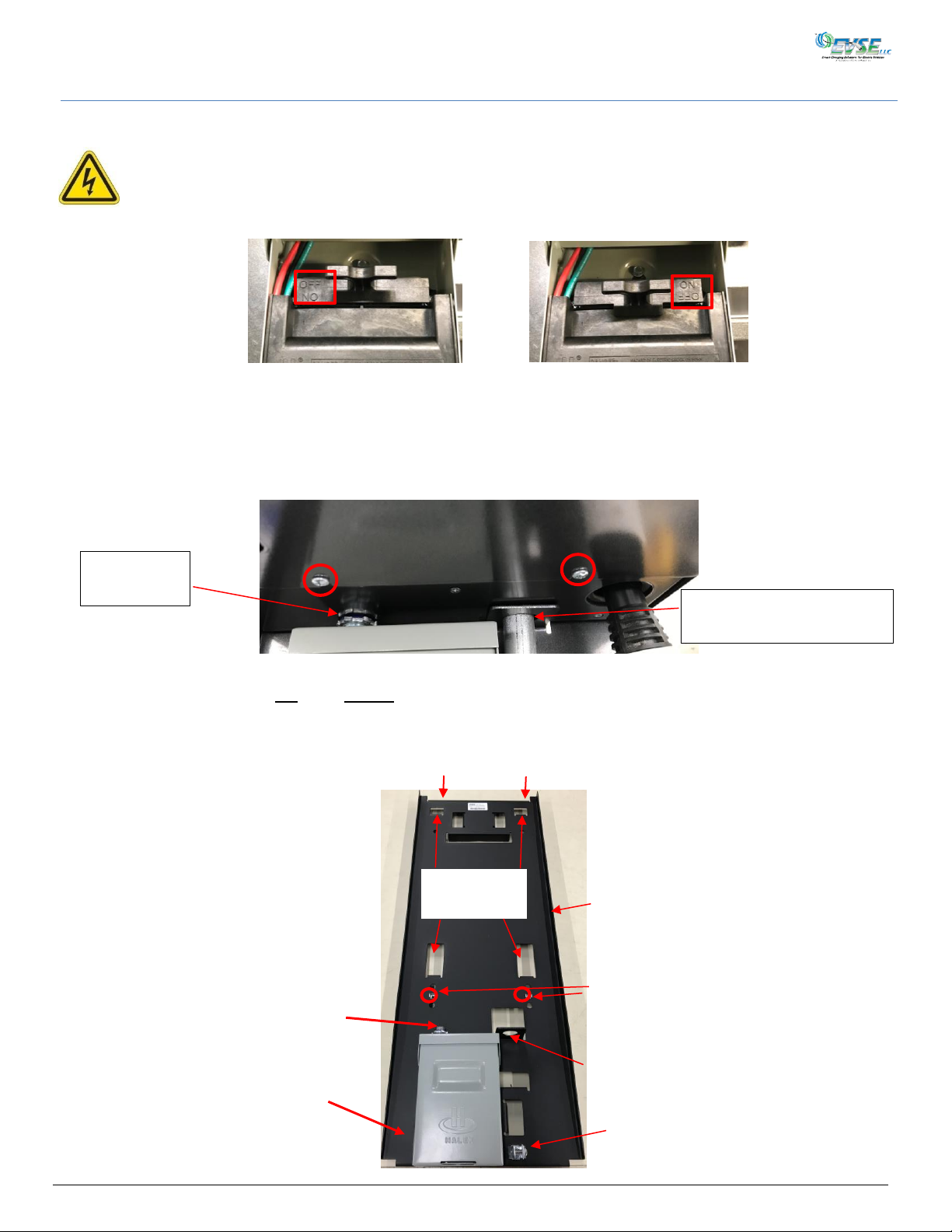
Figure 5
Nipple for
AC Access
Conduit RFID Reader/Serial
Connection
Power Disconnect
Box
Insert 3704
Hooks Here
Insert AC Wiring
Into 3704
Secure 3704
Screws Here
Conduit
Access Hole
Figure 6
Temporarily hang the 3704 on the top of the frame
5068-050
Mounting Frame
(OFF Position)
(ON Position)
Conduit
Clamp
Mounting the Model 3704
Note: It is assumed that the 5068-050 Mounting Frame has already been mounted to the utility pole. See the 5068-IN-050
Installation Sheet for more information.
WARNING: Make sure the Power Disconnect Handle inside the Power Disconnect Box (Figure 6) is in the OFF
position, with the words on the left. This position turns off the flow of electricity to the EVSE. (Figure
4).
Figure 4
Removing the Front Cover
The 3704 EVSE is shipped with the front cover on. Begin by removing the EVSE cover.
1. Using a T25 pin-in Torx screwdriver, loosen the two screws in the bottom of the cover (Figure 5).
2. Pull the cover slightly out at the bottom of the EVSE and slide down until it clears the ABS plastic cover at the top.
3. Carefully place the cover in a safe location until needed later.
Hanging The 3704 EVSE
3704-IG-A04xx Installation and User Manual Page 9
Page 16
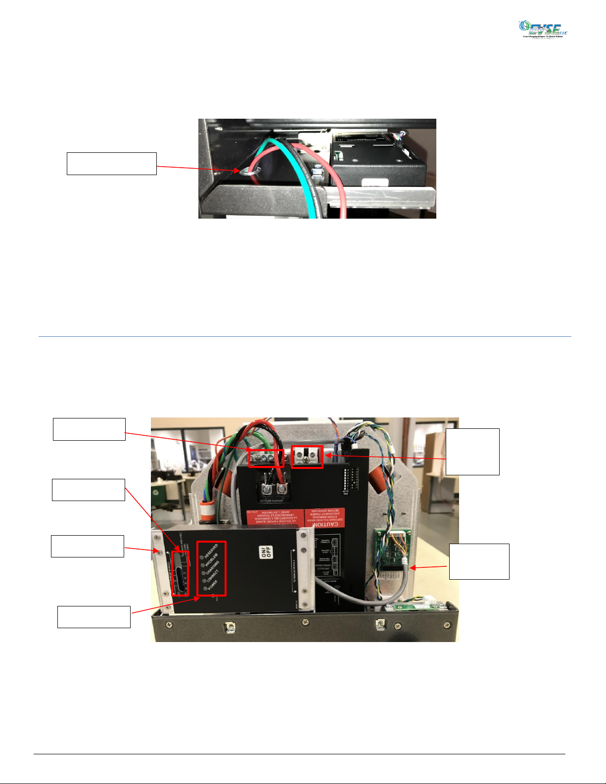
Dip Switches
Status LEDs
Figure 8
Connect
Power to
GFCI
Ground Bar
Data Router
AC Access Hole
RFID
Connector
1. With the mounting frame secured to the utility pole and the front cover removed from the EVSE, temporarily
hook/hang the EVSE on top of the mounting frame (Figure 6).
2. Pass the wiring coming up from the Power Disconnect Box (Figure 6) through the AC access hole into the EVSE
(Figure 7).
Figure 7
3. While making sure no wires are pinched, lift the EVSE up and insert its four hanging hooks into the mating slots in
the frame (Figure 6).
4. Secure the EVSE to the Mounting Frame with the two supplied ¼-20 x 5/8 screws (Figure 6).
5. Raise the top sealing nut on the top nipple on the Disconnect Box (Figure 5) so it contacts the bottom of the 3704
charger.
Wiring the EVSE for Power
1. Make sure the Power Disconnect Handle is in the OFF position, with the words on the left (Figure 4). This position turns
off the flow of electricity to the EVSE.).
2. Connect the corresponding power wires from the Disconnect Box to L1 (Red) and L2 (Black) to the GFCI (Figure 8). Attach
the incoming ground wire from the Disconnect Box to the GFCI’s Ground Bar (Figure 8).
3. Torque the power wires to 18.5 in-lb. For ground wire, to 20 in-lb.
3704-IG-A04xx Installation and User Manual Page 10
Page 17
Configuring J1772 Cable Operation
You now need to test cable operation, and then set it to lower the J1772 connector to the ADA height of 48 inches from the
ground each time a charging session is initiated.
Testing Basic Cable Operation
In order to initiate a charging session to lower the cable, you will need to use either a Fob or cellphone with a QR Code app,
or an ID card for an RFID Card Reader. It is assumed these options have already been installed.
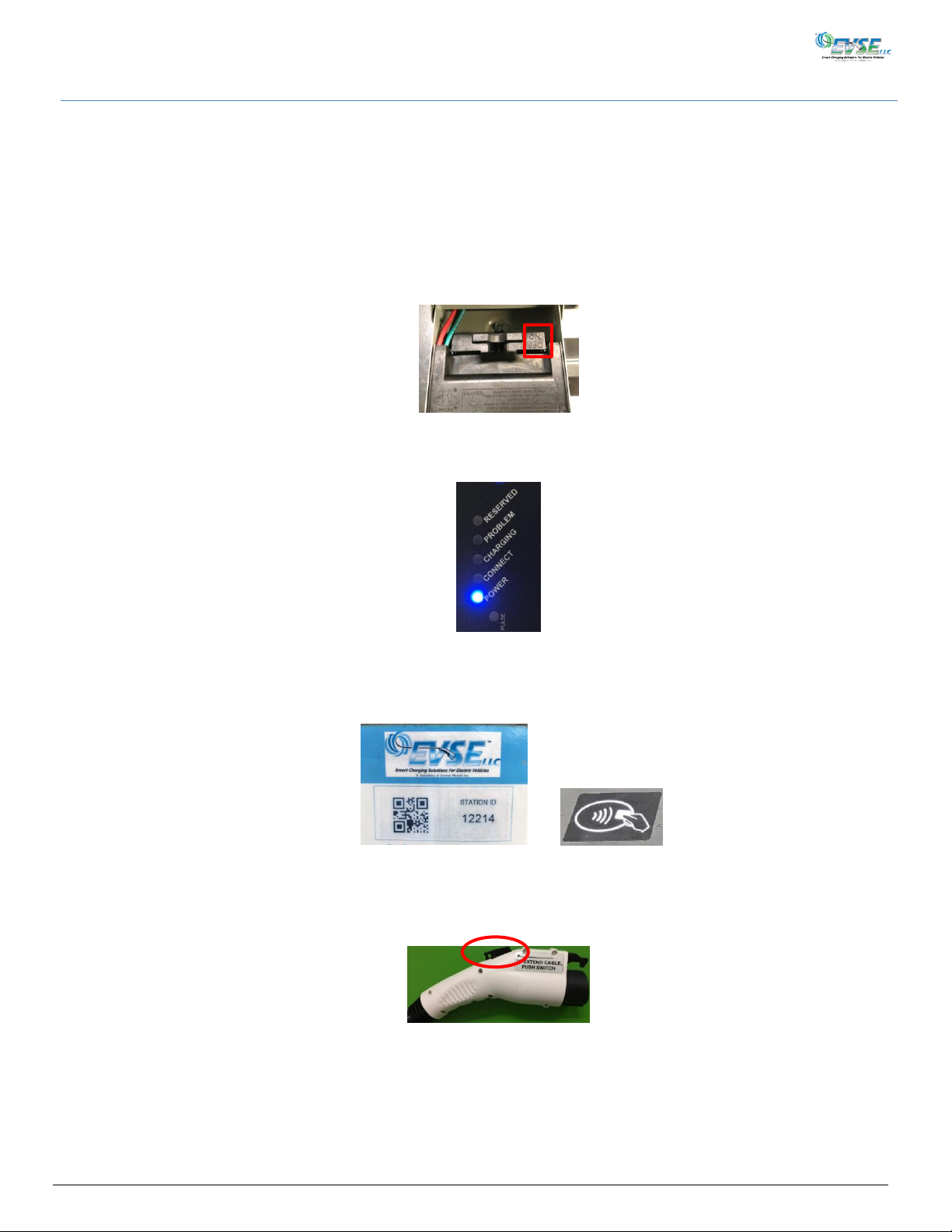
1. Open the Power Disconnect Box and place the Power Disconnect Handle in the ON (Figure 9) position, text on the
right. Close and lock the disconnect cover.
Figure 9
2. Observe the Data Router on the bottom of the EVSE (Figure 10). After it goes through its initial power-up cycle,
you should observe that only the blue Power LED is lit.
Figure 10
3. Use the Fob or cellphone QR Code app to initiate a charging session by placing it over the placard QR code (Figure
11), or use a badge over the RFID Reader. After verification, the yellow Connected LED starts blinking.
(QR Code) (RFID)
Figure 11
4. Press and hold the switch on the J1772 connector (Figure 12), lower the charging cable to its fullest length. Release
the switch.
Figure 12
5. After one minute, the cable will retract automatically.
3704-IG-A04xx Installation and User Manual Page 11
Page 18
OFF
ON
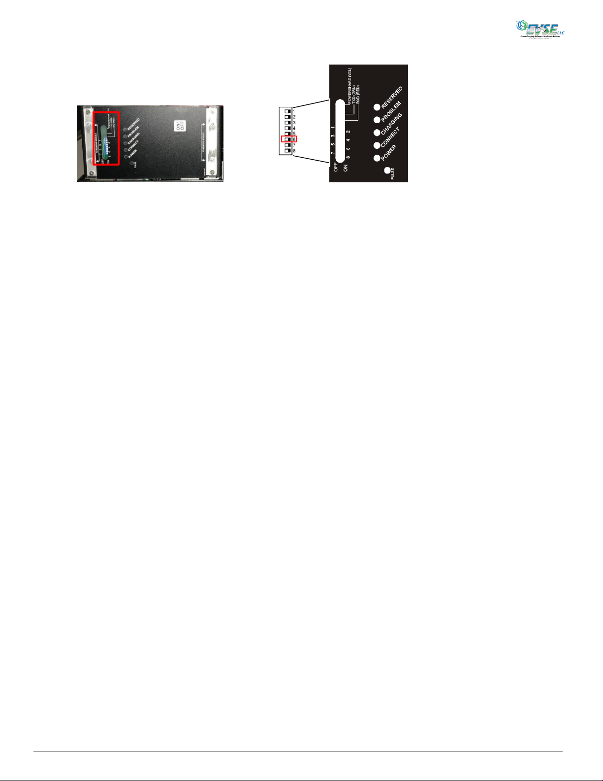
Setting the Cable Lowering Height for ADA
Figure 13
1. Set Switch 6 on the left side of the Data Router to OFF (Figure 13). The cable drops slightly and the blue and yellow
LEDs on the front of the Data Router start flashing.
2. Press and hold the switch on the J1772 connector (Figure 12) until the charging cable lowers to a height of 48 inches
from the ground (ADA height).
3. Set Switch 6 to ON. The cable automatically retracts, the yellow LED turns off and the blue LED stays solid.
4. To test, initiate a charging session, and ensure the cable drops to 48 inches from the ground.
3704-IG-A04xx Installation and User Manual Page 12
Page 19
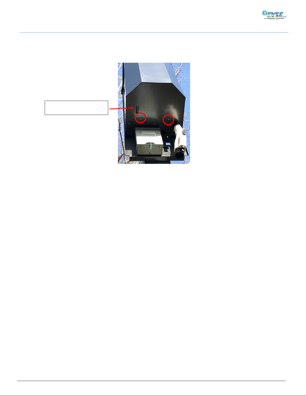
Replacing the Cover
Figure 14
Data Router Status LEDs
Replacing the cover involves the same steps, in opposite order, as removing the cover.
1. Slide the cover up into the top of the charger, making sure both sides of the cover are between the 5068-050
Mounting Frame and the charger, and lower the front into the cover’s screws (Figure 14).
2. Tighten the screws. Do not overtighten with power tools.
3704-IG-A04xx Installation and User Manual Page 13
Page 20

Installation Notes
It is important to fill out the following information for your records for each charging location.
Circuit ___________________________________________________
Panel Location _____________________________________________
Breaker Number ____________________________________________
Breaker Rating _____________________________________________
EVSE Station 1 Installer ID ____________________________________
Location ______________ Company _________________________
Number ______________ Name ____________________________
Tel. No. ___________________________
Date installed M D YR
Circuit ___________________________________________________
Panel Location _____________________________________________
Breaker Number ____________________________________________
Breaker Rating _____________________________________________
EVSE Station 2 Installer ID ____________________________________
Location ______________ Company _________________________
Number ______________ Name ____________________________
Tel. No. ___________________________
Date installed M D YR
Circuit ___________________________________________________
Panel Location _____________________________________________
Breaker Number ____________________________________________
Breaker Rating _____________________________________________
EVSE Station 3 Installer ID ____________________________________
Location ______________ Company _________________________
Number ______________ Name ____________________________
Tel. No. ___________________________
Date installed M D YR
Circuit ___________________________________________________
Panel Location _____________________________________________
Breaker Number ____________________________________________
Breaker Rating _____________________________________________
EVSE Station 4 Installer ID ____________________________________
Location ______________ Company _________________________
Number ______________ Name ____________________________
Tel. No. ___________________________
Date installed M D YR
3704-IG-A04xx Installation and User Manual Page 14
Page 21
SW1
OFF Selects standard retract pull-in force of ~15lbs
*ON Selects a higher retract pull-in force of ~25lbs
SW3
*OFF Not in Test Mode
ON Test Mode for adding to ZigBee Network
SW4 DO Time
*OFF DO (Door Open) On for Full Length of Charge Cycle
ON DO (Door Open) is Pulsed Like a Door Status Switch
(Pulsed for 3 Seconds)
SW6
*OFF Not in ADA Learning Mode
ON In ADA Learning Mode
SW7
*OFF Inactivity Timer Enabled, 1 Min
Also EVSE Activated by Local “On” Key (No Payment Module)
ON Inactivity Timer Enabled, 15 Min
Also EVSE Activated by Payment Module
SW8
*OFF 40A Breaker
ON 50A Breaker
SW 2, 5
For Future Use
*DEFAULT SETTINGS
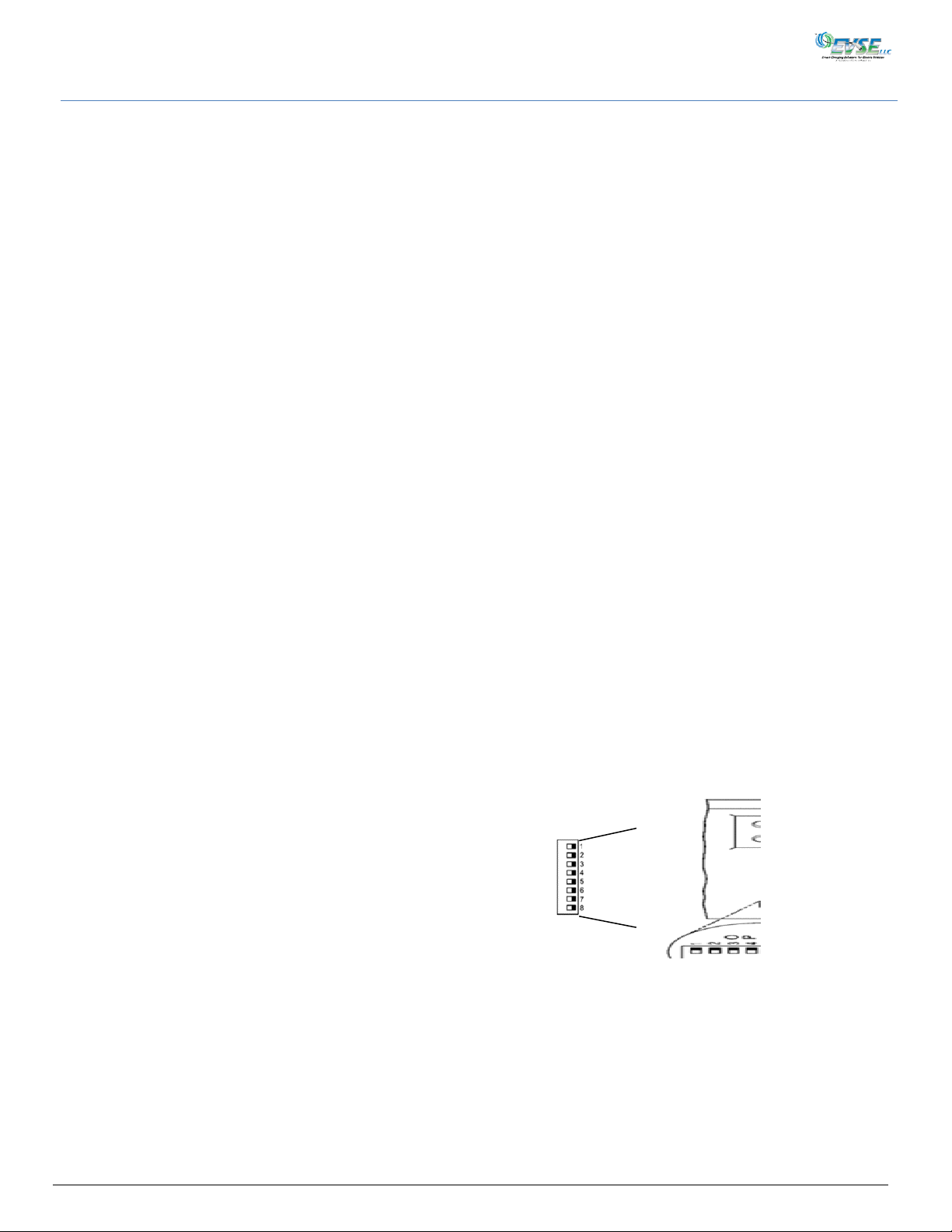
Figure 15
Dip Switch Settings
The Model 3704 is equipped with an 8-position dip switch on the Data Router (Figure 15), to personalize each installation.
Switch 1 allows selectable pull-in force: SW1 OFF = ~15lbs., SW1 ON (Default) = ~25lbs.
Switch 2 is not currently used and is reserved for future applications.
Switch 3 puts the EVSE into Test Mode for connecting to a Payment Module via a ZigBee network. See the 3725-UG-002
Payment Module User Guide for information about adding the 3704 to the network. OFF = Not in Test Mode; ON = In Test
Mode
Switch 4 provides an interface for Control Access Security Systems (CASS).
Switch 5 is not currently used and is reserved for future applications.
Switch 6 puts the 3704 into learning mode to determine the initial lowering height of the J1772 cable for ADA compliance (48
inches). When ON, press the switch on the J1772 to extend the cable to the proper height, then set the switch back to OFF.
The initial lowered height is locked into the 3704.
Switch 7 sets the amount of time the user has to engage the J1772 connector after authorization. In the case where a
payment module is not used and the 3704 ON button is the actuation mechanism, the default OFF setting of this switch
allows the user one minute to engage the J1772 connector in the vehicle. In the situation where authorization via a payment
module is required prior to the initiation of charging, the ON position for Switch 7 allows a 15 minutes timeout for the
authorization. In other words, if the J1772 plug is not engaged in 15 minutes, a new authorization must be obtained. This
allows the user time to walk from the payment module, which might located some distance from the 3704, to the vehicle to
plug in the connector.
Switch 8 is used to select the breaker size when two 3704s share a circuit breaker. When the switch is OFF to select an
installed 40A breaker, the maximum current delivered to each vehicle is limited to 16A. If only one vehicle is connected, it
can draw up to the full 30A. When the switch is ON to select an installed 50A breaker, the maximum current delivered to
each vehicle is limited to 20A. Again, if only one vehicle is charging, it can draw up to the full 30A.
3704-IG-A04xx Installation and User Manual Page 15
Page 22
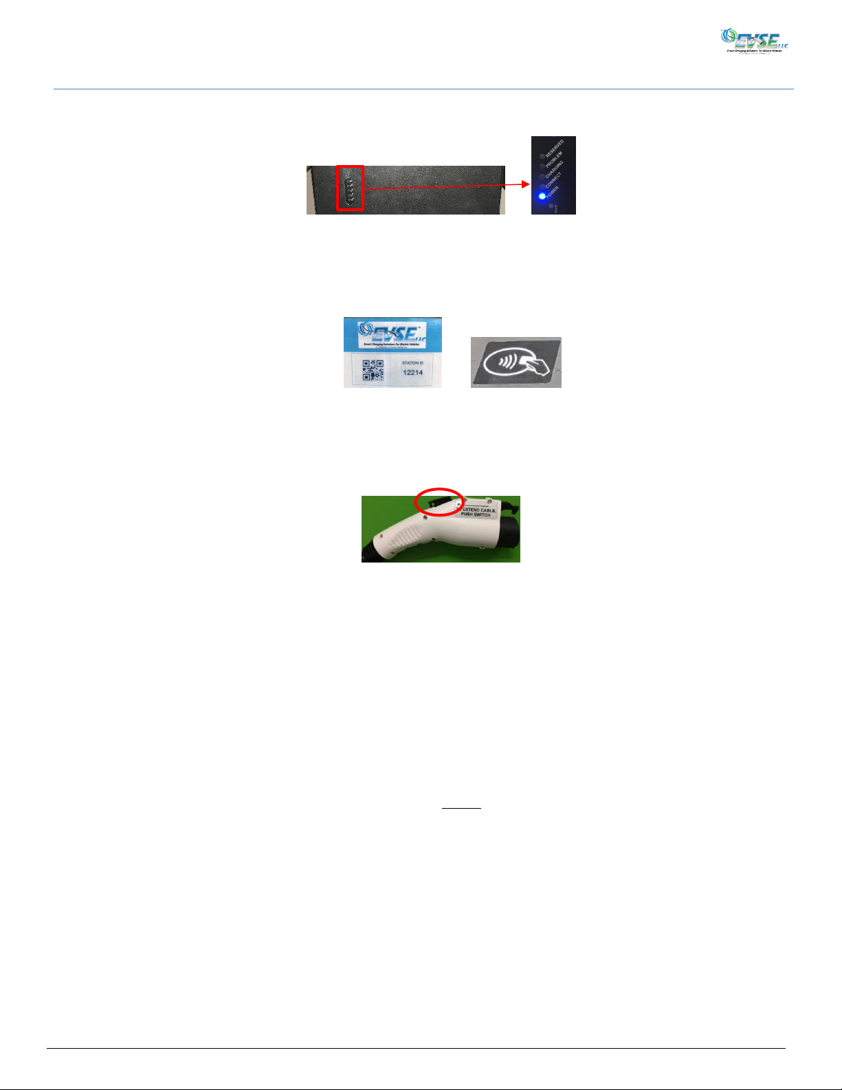
Figure 12
Figure 18
Operation
1. Open the lid to your electric vehicle’s (EV) charging receptacle.
2. Look up and observe the Data Router on the bottom of the EVSE (Figure 16). The blue Power LED is on.
Figure 16
3. Click your Fob, or if you are using the QR Reader, place the QR Code on your cellphone over the QR code on the
placard (Figure 17) on the utility pole. If you are using the RFID Reader, place your card/badge over the symbol on
the RFID Reader. The yellow Connect LED will start blinking and the cable will lower to the 48-inch ADA height.
(QR Code) (RFID)
Figure 17
4. Press and hold the switch on the J1772 connector (Figure 18), walk the charging cable to your EV, and plug the
J1772 connector into the charging receptacle. The yellow Connected LED turns off and the green Charging LED
begins flashing. Your EV’s battery is now charging.
5. The green Charging LED turns solid when the EV’s battery is fully charged. When charging is complete, disconnect
the J1772 connector from the EV’s charging receptacle by pressing the switch on top of the charging connector and
pulling it out. The green Charging LED turns off. The yellow Connect LED blinks until the cable is fully retracted and
then turns off. Only the blue Power LED remains on.
6. The cable will retract automatically when removed from the EV’s charging receptacle. If you pull the charging cable
while it is retracting or if the cable gets caught on anything, cable retraction will stop for safety reasons. The cable
will make one additional attempt to retract. Thereafter, pressing and releasing the switch on the J1772 connector
(Figure 18) will restart the cable retraction process. If this is the one hundredth time the cable has been extended
for charging, the built-in Cable Maintenance Program will automatically extend the cable to its full 25-foot length
and then fully retract it back up into the EVSE when the cable is unplugged from the EV.
NOTE: If you remove the charging cable from the EV’s receptacle before the battery is fully charged, the charging process
terminates, and the cable begins to retract. (Power is removed from the connector prior to its full removal from the
receptacle as a safety precaution.) Let the cable fully retract and restart the process. Retraction will take up to 20
seconds.
Built-in Safety: When power is applied to the EV, the EVSE monitors the current being drawn. Should the current exceed the
3704-IG-A04xx Installation and User Manual Page 16
maximum levels set by the breaker switches, the EVSE will disconnect the power from the EV and the red
Problem LED will turn on. If there was a ground fault, the EVSE will attempt three closures after a short
delay. There is no re-closure with an over-current trip.
Page 23
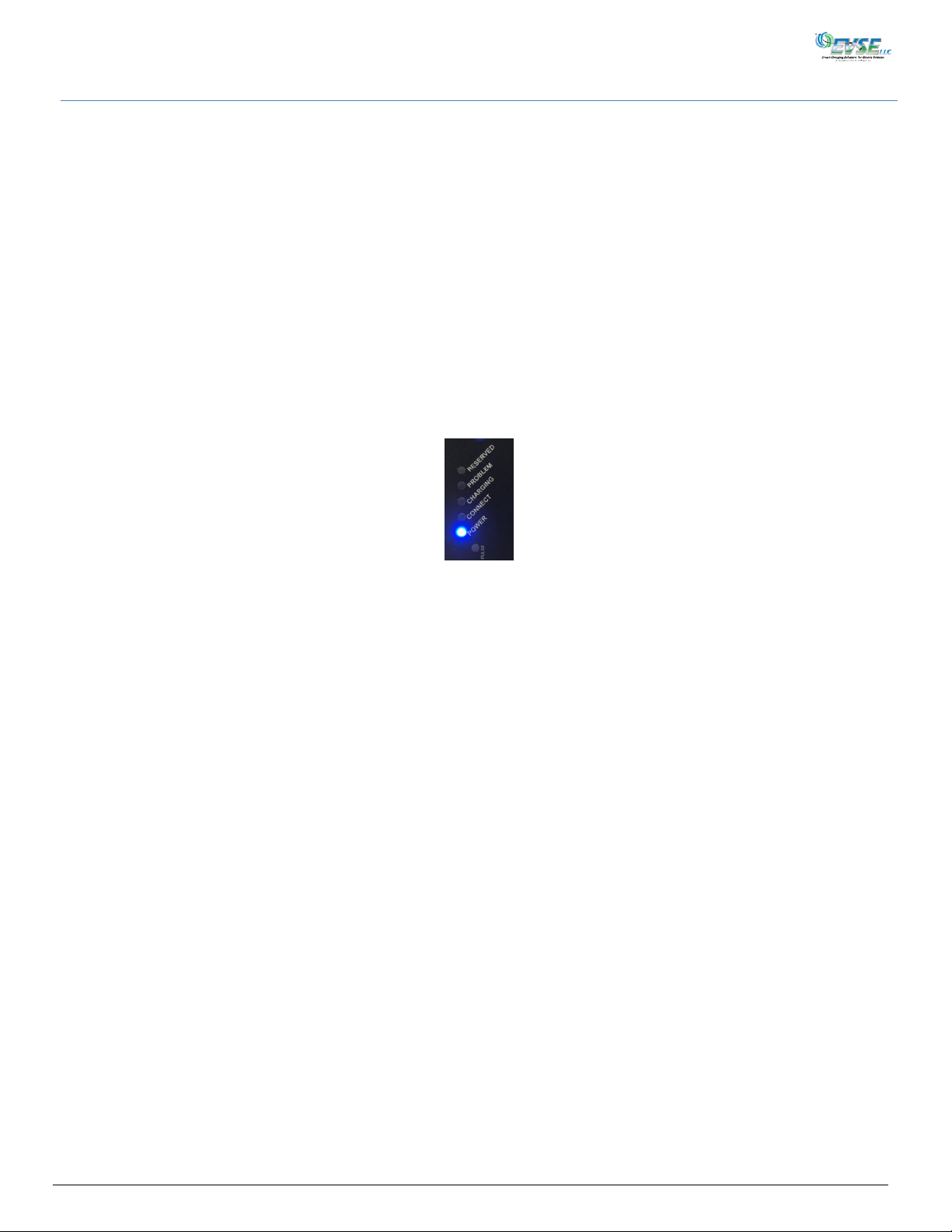
Figure 19
Testing and Fault Modes
With the communications required between the EVSE and the electric vehicle, it is recommended that the installer use a
Control Module Inc. Model 3840-001 hand-held tester. This will thoroughly check out the EVSE, before using an Electric
Vehicle.
The primary function of the Data Router (Figure 19) is to display its operational status. The unit is equipped with five status
LEDs:
Blue (Power): Indicates primary power is applied.
Yellow (Connect): When EVSE is ready to charge the car, it starts blinking, indicating the cable is ready to be connected.
Once plugged into the car, it shuts off.
Green (Charging): After plugging the J1772 connector into the car it starts blinking, indicating the car is charging. Once
the car is fully charged, it turns on solid.
Red (Problem): Indicates a problem has occurred. (Refer to the Status Indicator Chart, on page 18).
Orange (Reserved): When lit, the EVSE has been reserved for use by another vehicle.
See the Status Indicator chart on the following page for complete status details.
3704-IG-A04xx Installation and User Manual Page 17
Page 24

NORMAL USE MODES:
BLUE
YELLOW
GREEN
RED 1 Line Voltage On
F/2
F/2
F/2
F/2
2
Self-Diagnostics Pass
Line Voltage is between 208-240VAC
Ground Connection Present
ON X X
X
3
Waiting to connect to EV
ON
SF X X
4
Cable is connected
ON
ON X X
5
Random start time activated – Charging
begins in 2-5 minutes
ON X SF X 6
Vehicle in charge mode (Level 2)
ON X FF X 7
Vehicle charged
ON X ON X 8
Cable is connected/standby mode (ext. contact) (Level 1
charge)
ON
SF
SF X 9
Cable is connected/off mode (ext. contact)
ON
FF
FF
X
FAULT MODES:
1
Ground wire is NOT connected
FF
X
X
ON
2
Line Voltage Is less than 208VAC
SF
X
X
SF
3
Clutch/Cable Motor Failure
X
SF
X
ON
4
GFCI Trip (reclosure in process)
SF
SF
X
SF
5
GFCI Trip
SF
SF
X
ON
6
GFCI Circuit Failure
SF
X
X
ON
7
Over Current Trip
FF
FF
X
ON
8
Stall Trip (reclosure in process)
ON
SF
X
SF
9
Stall Trip
ON
SF
X
ON
10
Pilot Problem
ON
ON
X
SF
11
Ventilation Required
ON
X
X
SF
12
Display Offline (comm. problem with sequencer)
FF
X
X
X
13
Load/No Load Voltage Differential Problem
X
X
X
FF
PROGRAM MODES:
1
In Program Mode
SF
<--
SF
<--
SF
<--
SF
<--
2
Program Completed/program connector attached
ON
ON
ON
ON
Legend
F/2 = Flash once for 2 sec. X = Led is off
SF = Slow flash (1/sec) <-- = In Sequence
FF = Fast flash (3/sec)
Status Indicator Chart (Power) (Connected) (Charging) (Problem)
3704-IG-A04xx Installation and User Manual Page 18
Page 25
User Maintenance
WARNING:
Ensure electrical power has been shut-off at the source before starting any electrical work.
Follow state and local codes.
AVERTISSEMENT:
Assurer l'alimentation électrique a été fermeture à la source avant de commencer les travaux
d'électricité.
Perform the following preventative maintenance at least monthly:
The J1772 connector should be checked for foreign matter; cleaned and dried with a mild detergent (safe for
plastics), and then allowed to dry.
The power cord and power connector should be inspected for wear and tear or cuts exposing wires.
Report mechanical damage.
Moving, Transporting, and Storage
Should the 3704 EVSE have to be relocated, remove the unit in the reverse order that it was installed.
Do not lift or carry the unit using the EV cable.
Ensure all wiring is stored inside the housing.
Bag all attaching hardware and secure on/in the unit.
Store the unit in a dry, low humidity area.
Protect the unit using appropriate packaging.
3704-IG-A04xx Installation and User Manual Page 19
Page 26

Customer Support
Should questions about installation, operation, optional features, maintenance or service arise, please call Technical
Support at 1-888-753-8222 between the hours of 8:30 am to 5:00 pm EST, Monday to Friday.
Letter
Service Department
Attn: Jack Batalha, Director Product Support
Control Module Inc.
89 Phoenix Avenue
Enfield, CT 06082
Fax
1-860-741-6064
E-mail
3704-IG-A04xx Installation and User Manual Page 20
Page 27

Warranty
For Standard Terms and Conditions, and Warranty information:
http://controlmod.com/technical-support/order-terms/
3704-IG-A04xx Installation and User Manual Page 21
Page 28

EVSE LLC
A Division of Control Module, Inc.
89 Phoenix Ave., Enfield, CT 06082
Local Phone: 860.745.2433
Toll Free Phone: 800.722.6654
evse.controlmod.com
SAVINGS, LOSS OF EARNINGS, GOODWILL, COSTS OF COVER, IN EACH CASE RELATING TO THIS WARRANTY OR TO THE EQUIPMENT, EVEN IF
SUCH DAMAGES WERE FORESEEABLE AND EVEN IF THIS WARRANTY FAILS OF ITS ESSENTIAL PURPOSE.
3704-IG-A04xx Installation and User Manual Page 22
 Loading...