

Page 1

5910 Ethernet Gateway
Hardware Manual
CONTROL
MICROSYSTEMS
SCADA products... for the distance
48 Steacie Drive Telephone: 613-591-1943
Kanata, Ontario Facsimile: 613-591-1022
K2K 2A9 Technical Support: 888-226-6876
Canada 888-2CONTROL
Page 2

1
5910 Ethernet Gateway Hardware Manual
©2000 - 2006 Control Microsystems Inc.
All rights reserved.
Printed in Canada.
Trademarks
TeleSAFE, TelePACE, SmartWIRE, SCADAPack, TeleSAFE Micro16 and
TeleBUS are registered trademarks of Control Microsystems Inc.
All other product names are copyright and registered trademarks or trade names
of their respective owners.
Material used in the User and Reference manual section titled SCADAServer
OLE Automation Reference is distributed under license from the OPC
Foundation.
5910 Ethernet Gateway Hardware Manual
October 19, 2007
Page 3

2
Table of Contents
1 OVERVIEW .................................................................................................... 3
2 IMPORTANT SAFETY INFORMATION ......................................................... 4
3 INSTALLATION ............................................................................................. 5
3.1 Field Wiring .................................................................................................... 5
3.2 Ethernet Connection ...................................................................................... 6
3.3 Power Connections ........................................................................................ 6
3.4 I/O Bus Connection ........................................................................................ 6
3.5 External Power Connection using an AC adapter .......................................... 6
3.6 External Power Connection using an external power source ......................... 7
3.7 Configuration Jumpers ................................................................................... 7
3.8 LED Indicators ............................................................................................... 7
4 OPERATION .................................................................................................. 9
5 MAINTENANCE ........................................................................................... 10
5.1 Troubleshooting ........................................................................................... 10
6 SPECIFICATIONS ....................................................................................... 11
7 APPROVALS AND CERTIFICATIONS ....................................................... 12
Index of Figures
Figure1: 5910 Module Layout .............................................................................................. 5
Figure 2: 5905 Ethernet RJ-45 Connection ......................................................................... 6
5910 Ethernet Gateway Hardware Manual
October 19, 2007
Page 4

3
1 Overview
The Model 5910 Ethernet Switch is a five port unmanaged switch used to route Ethernet
messages. It is easy to install and operate as no configuration is necessary. Once the Ethernet
connections are made and the unit is powered up, the 5910 will begin to operate.
The 5910 mounts on a DIN rail and is powered from the 5V available in SCADAPack
controllers and other 5000 series systems. The 5910 can also be powered from 11-30Vdc
sources such as 12Vdc batteries, 24Vdc power supplies or AC adapters. The 5910 is
available with a desktop mounting option.
Applications include in-plant I/O and connectivity between SCADAPacks and operator
workstations, other PLC devices and SCADA systems communications that uses 10BaseT
(10 Mbps) or 100BaseT (100 Mbps) in an industrial environment.
5910 Ethernet Gateway Hardware Manual
October 19, 2007
Page 5
4
2 Important Safety Information
WARNING !
EXPLOSION HAZARD - SUBSTITUTION OF COMPONENTS MAY
IMPAIR SUITABILITY FOR CLASS 1, DIVISION 2.
WARNING !
EXPLOSION HAZARD – WHEN IN HAZARDOUS LOCATIONS, TURN
OFF POWER BEFORE REPLACING OR WIRING MODULES.
WARNING !
EXPLOSION HAZARD - DO NOT DISCONNECT EQUIPMENT
UNLESS POWER HAS BEEN SWITCHED OFF OR THE AREA IS
KNOWN TO BE NONHAZARDOUS.
Power, input and output (i/o) wiring must be in accordance with Class I, Division 2 wiring
methods Article 501-4 (b) of the National Electrical Code, NFPA 70 for installations in the
U.S., or as specified in Section 18-1J2 of the Canadian Electrical Code for installations
within Canada and in accordance with the authority having jurisdiction.
5910 Ethernet Gateway Hardware Manual
October 19, 2007
Page 6
5
3 Installation
Link/Act
Speed
Port1 Port2 Port3 Port4 Port5
Power
External Power
11-30Vdc
Bus Power 5V
P8
Port1 Port2 Port3 Port4 Port5
J1P2P1
P7
P3
11-30Vdc
+ -Power Input
4 3 2 1
The 5910 Ethernet Switch is available in two standard versions, the model 5910 and the
model 5910SA. The model 59105 is a standard 5000 Series module that connects to the
system I/O Bus as an integrated part of a Control Microsystems system. The model 5910SA
is a stand-alone version of the 5910 and is used with other devices such as personal
computers. Both versions of the modem are identical in every respect except that the
5910SA has rubber feet for desktop mounting.
3.1 Field Wiring
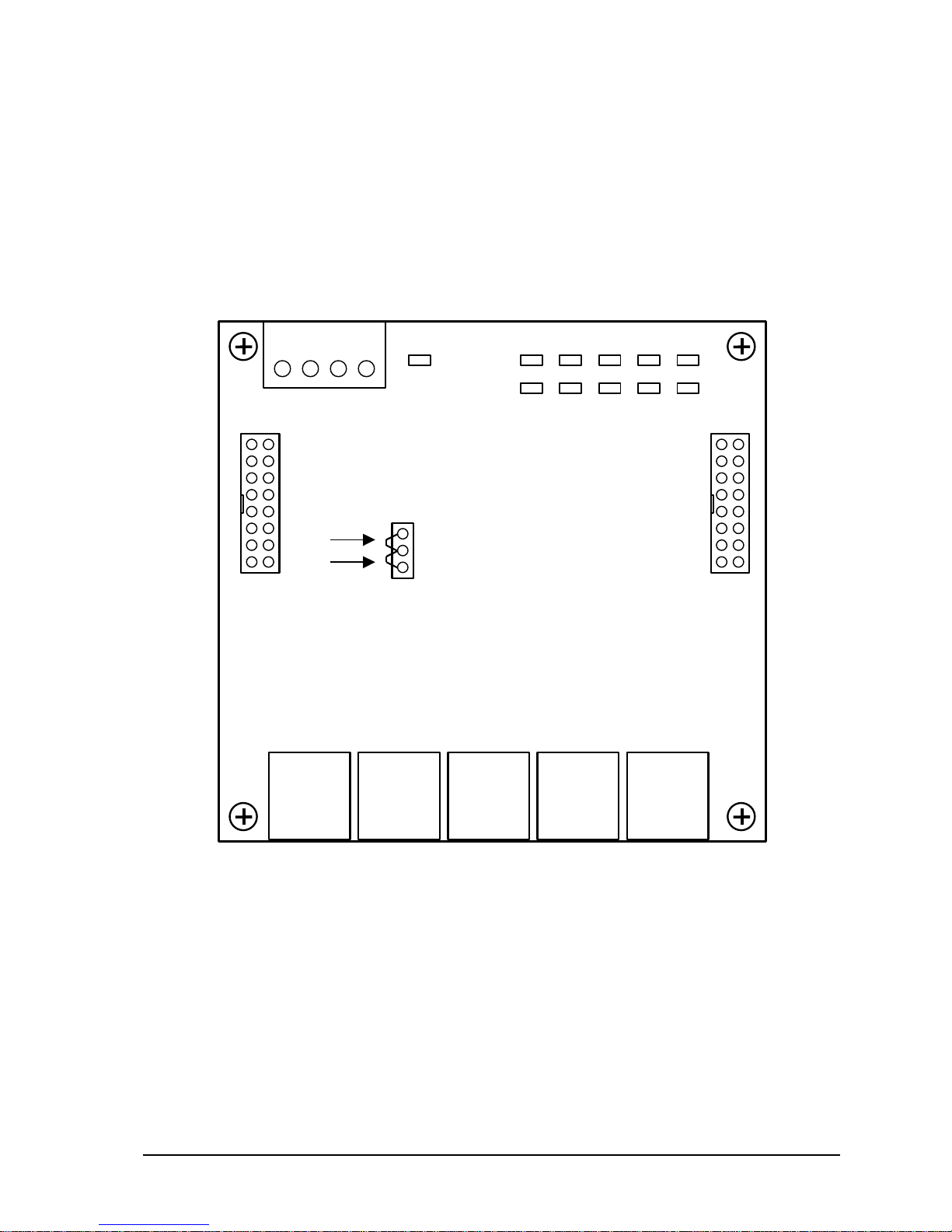
The 5910 module has six connectors for field wiring. Refer to Figure1: 5910 Module
Layout for the location of these connectors.
The five Ethernet connections are terminated at the RJ-45 modular jacks labeled Ports1 through
5. The RJ-45 modular jack pin-out is compatible with straight-through Ethernet cables and
cross-over Ethernet cables. See the Ethernet Connection section for more information.
External power in the range of 11 to 30Vdc in maybe connected to pins 1 and 2 of P8. External
power may come from any DC power source such as a 12V battery, 12Vdc AC adapter or
5910 Ethernet Gateway Hardware Manual
October 19, 2007
Figure1: 5910 Module Layout
Page 7

6
24Vdc power supply. See the Configuration Jumpers section for setting J1 and the
RJ-45
1: TD/RD+
2: TD/RD3: RD/TD+
4: nc
5: nc
6: RD/TD7: nc
8: nc
3 4 5 2 6 7 8 1
Specifications for the current requirements.
Note: An AC adapter cannot be used in Hazardous Locations.
3.2 Ethernet Connection
The Ethernet network connects to the RJ-45 modular jacks labeled Port1 through Port5. The
RJ-45 jack mates with 8-pin connector and cable assemblies common to Ethernet 100Base-T
applications. Use data quality twisted pair cable. For best performance use shielded cable.
Pins 1,2,3 and 6 are used. Pins 4,5,7, and 8 are not used. See Figure 2: 5905 Ethernet RJ-45
Connection for pin connections. The Ethernet RJ-45 ports are MDI/MDIX Auto crossover
compatible. The allows the use of straight-through or cross-over cables.
Figure 2: 5905 Ethernet RJ-45 Connection
3.3 Power Connections
The 5905 module may be powered in any one of the following ways:
5Vdc applied to the 5910 from the I/O Bus.
11-30Vdc applied to the 5910 on P8.
NOTE: The 5905 module is for use with Class 2 output power supplies only.
3.4 I/O Bus Connection
The 5910 module is normally powered through the connection to the system I/O Bus. The
5910 module is connected to the system I/O Bus using a cable connected to P1 or P2. Refer
to the System Configuration Guide, at the beginning of this manual, for complete
information on the system I/O Bus cabling. A jumper link must be installed in the bottom or
“Bus power 5V” position on J1.
3.5 External Power Connection using an AC adapter
The 5910 Ethernet Switch can be powered using a 12Vdc AC adapter (Control
Microsystems part number: 210056). The AC adapter plugs into a 120Vac supply and
provides 12Vdc to the 5910. A jumper link must be installed in the upper or “External
Power 11-30V” position on J1.
5910 Ethernet Gateway Hardware Manual
October 19, 2007
Page 8

7
Ensure the AC adapter is not connected to the 120Vac supply.
Jumper
Description
Position
J1
Input power source is from
an AC adapter or external
power source.
Upper or “External Power 11-30V”
J1
Input is 5V from the Bus
on P1 or P2.
Bottom or “Bus power 5V”
LED
Function
Power
On when power is applied to the module. Power source can
be Bus or External.
Link/Activity
One LED for each port. On when a link (proper Ethernet
Locate connector P8 on the 5910 module. Refer to Figure1: 5910 Module Layout for the
location of P8.
The output cable end should be factory installed on a four position removable terminal block.
The negative output connects to pin 1 and the positive output connects to pin 2. Pins 3 and 4 are
not used.
Insert the terminal block into onto connector P8.
Plug the AC adapter into a 120Vac supply.
Note: The 12Vdc adapter connection cannot be used in Hazardous Locations.
3.6 External Power Connection using an external power source
The 5910 Ethernet Switch can be powered using 11-30Vdc power source such as a 24Vdc
power supply. A jumper link must be installed in the upper or “External Power 11-30V”
position on J1.
Note: A Class 2 power source must be connected to the External Power 11-30Vdc input on
P8.
Ensure the power source is off.
Locate connector P8 on the 5910 module. Refer to Figure1: 5910 Module Layout for the
location of P8.
Connect the power source outputs to the terminal block. The negative output connects to pin 1
and the positive output connects to pin 2. Pins 3 and 4 are not used.
Insert the terminal block into onto connector P8.
Turn the power source on.
3.7 Configuration Jumpers
The 5910 Ethernet Switch uses a single configuration jumper link for selecting the input
power source.
3.8 LED Indicators
The 5910 module has 11 LEDs to indicate module operation and status. The SCADAPack
controllers cannot disable the power to these LEDs.
5910 Ethernet Gateway Hardware Manual
October 19, 2007
Page 9

5910 Ethernet Gateway Hardware Manual
8
LED
Function
connection) has been established. Flickers when data is
being transmitted or received.
Speed
Off for 10 Mbps operation. On for 100 Mbps operation.
October 19, 2007
Page 10

9
4 Operation
The 5910 is a layer 2, five port unmanaged switch. No programming or configuration is
required to use the 5910. Once the Ethernet connections are made and the 5910 is powered it
will begin to operate. Unlike an Ethernet hub that broadcasts all messages to all ports, the
5910 Ethernet Switch will route messages only out of the appropriate port. Both 10BaseT
(10 Mbps) and 100BaseTx (100 Mbps) can be used on any of the ports. These ports will
auto0sense the speed and accommodate cross-over or straight-through cables.
5910 Ethernet Gateway Hardware Manual
October 19, 2007
Page 11

10
5 Maintenance
Problem
Solutions
Power LED is not on.
Check power source. If the input is 5V from the
Bus on P1 or P2 then the J1 jumper should be
in the bottom or “Bus power 5V” position. If the
input is 11-30Vdc from P8 then the J1 jumper
should be in the upper or “External Power 1130V” position.
This module requires no routine maintenance. If the module is not functioning correctly,
contact Control Microsystems Technical Support for more information and instructions for
returning the module for repair.
5.1 Troubleshooting
5910 Ethernet Gateway Hardware Manual
October 19, 2007
Page 12

11
6 Specifications
Ethernet switch
type
5 ports, unmanaged, store & forward, 10/100BaseT
Ethernet
Terminations
RJ45 ports (shielded)
Protocols
IEEE 802.3, IEEE 802.3u (TBC), IEEE802.3x
Speed and
connection
Auto-detecting 10/100 Mbps operation
MDI/MDIX Auto crossover (no need for cross-wired cables)
Broadcast storm
protection
Yes. 1% of bandwidth.
Memory
bandwidth
1.4 Gbps
Full or half
duplex operation
Full duplex IEEE802.3x and half duplex back pressure flow
control
MAC addresses
supported
Dedicated lookup engine with 1K MAC addresses. Learning,
aging and migration.
Ethernet
isolation
1500Vrms
Visual Indicators
Each port - ACT/LINK and 10/100 (Speed).
Power
Input Power
External Power: 11-30Vdc
1.8W at 12Vdc
2.2W at 30Vdc
Bus Power: 5V at 375mA
Input Power
Terminations
4 pole terminal strip and removable terminal block
12 to 22 AWG
Dimensions
4.25 inch (144 mm) wide
4.625 inch (118 mm) high
2.00 inch (51 mm) deep
Mounting
desktop, rubber feet or 7.5 x 35 DIN rail
Packaging
corrosion resistant zinc plated steel with black enamel paint
Environment
5% RH to 95% RH, non-condensing
–40oC to 70oC
–40oF to 158oF
Disclaimer: Control Microsystems reserves the right to change product specifications without
notice. For more information visit www.controlmicrosystems.com .
5910 Ethernet Gateway Hardware Manual
October 19, 2007
Page 13

12
7 Approvals and Certifications
Safety
Non-Incendive Electrical Equipment for Use in Class I, Division
2 Groups A, B, C and D Hazardous Locations.
Digital
Emissions
FCC Part 15, Subpart B, Class A Verification
EN61000-6-4: 2001 Electromagnetic Compatibility Generic
Emission Standard Part2: Industrial Environment
C-Tick compliance. Registration number N15744.
Immunity
EN61000-6-2: 2001 Electromagnetic Compatibility Generic
Standards Immunity for Industrial Environments
Declaration
This product conforms to the above Emissions and Immunity
Standards and therefore conforms with the requirements of
Council Directive 89/336/EEC (as amended) relating to
electromagnetic compatibility.
The Low Voltage Directive is not applicable to this product.
5910 Ethernet Gateway Hardware Manual
October 19, 2007
 Loading...