

Page 1

5604 Input/Output (I/O) Module
Hardware Manual
CONTROL
MICROSYSTEMS
SCADA products... for the distance
48 Steacie Drive Telephone: 613-591-1943
Kanata, Ontario Facsimile: 613-591-1022
K2K 2A9 Technical Support: 888-226-6876
Canada 888-2CONTROL
Page 2

1
5604 Input/Output (I/O) Module - Hardware Manual
©2000 - 2005 Control Microsystems Inc.
All rights reserved.
Printed in Canada.
Trademarks
TeleSAFE, TelePACE, SmartWIRE, SCADAPack, TeleSAFE Micro16 and
TeleBUS are registered trademarks of Control Microsystems Inc.
All other product names are copyright and registered trademarks or trade names
of their respective owners.
Material used in the User and Reference manual section titled SCADAServer
OLE Automation Reference is distributed under license from the OPC
Foundation.
5604 Input/Output (I/O) Module - Hardware Manual
October 19, 2007
Page 3

2
Table of Contents
1 OVERVIEW .................................................................................................... 5
2 IMPORTANT SAFETY INFORMATION ......................................................... 6
3 FIELD WIRING CONNECTORS .................................................................... 7
4 POWER SUPPLY .......................................................................................... 8
4.1 Overview and Requirements..................................................................... 8
4.2 Power Supply Input Connections .............................................................. 8
4.2.1 Recommended AC Power Supply Configuration ................................. 9
4.2.2 Recommended 24V Power Supply Configuration ............................. 10
4.2.3 Recommended Battery Configuration ............................................... 11
4.2.4 Recommended 5103 Power Supply Configuration............................ 12
4.3 System Grounding .................................................................................. 13
4.4 Power Management Features ................................................................ 13
4.4.1 DC/DC Converter Control .................................................................. 13
4.4.2 VLoop Power Control ........................................................................ 14
4.4.3 VLoop Over-Current Protection ......................................................... 14
5 ANALOG INPUTS ........................................................................................ 15
5.1 Current or Voltage Mode ........................................................................ 15
5.2 Range and Resolution ............................................................................ 16
5.3 Wiring ..................................................................................................... 17
5.3.1 Wiring Examples ............................................................................... 17
5.4 Filtering and Response Timing ............................................................... 18
6 ANALOG OUTPUTS .................................................................................... 19
6.1 Current Outputs ...................................................................................... 19
6.2 Voltage Outputs ...................................................................................... 20
6.3 Range and Resolution ............................................................................ 20
7 DIGITAL I/O ................................................................................................. 21
7.1 Digital Inputs ........................................................................................... 21
5604 Input/Output (I/O) Module - Hardware Manual
October 19, 2007
Page 4

3
7.2 Digital Outputs ........................................................................................ 21
7.3 Internal DIO ............................................................................................ 21
7.4 Wiring Examples ..................................................................................... 23
8 SERIAL COMMUNICATION ........................................................................ 24
8.1 COM3 RS-232 Serial Port ...................................................................... 24
8.2 RJ-45 Modular Connector for RS-232 .................................................... 24
8.3 RS-232 Wiring Examples ....................................................................... 25
8.4 RS-232 Cables ....................................................................................... 25
8.4.1 RJ-45 to DE-9S DTE ......................................................................... 25
8.4.2 RJ-45 to DE-9P DCE ......................................................................... 27
9 OPERATION ................................................................................................ 28
9.1 LED Indicators ........................................................................................ 28
10 SPECIFICATIONS ....................................................................................... 29
10.1 General ................................................................ ................................... 29
10.2 Communications ..................................................................................... 29
10.3 Visual Indicators ..................................................................................... 30
10.4 Power Supply .......................................................................................... 30
10.5 Analog Inputs .......................................................................................... 30
10.5.1 Inputs 0-7 .......................................................................................... 30
10.5.2 Input 8 ............................................................................................... 31
10.6 Analog Outputs ....................................................................................... 31
10.7 Digital Inputs ........................................................................................... 32
10.8 Digital Outputs ........................................................................................ 33
11 APPROVALS AND CERTIFICATIONS ....................................................... 34
Index of Figures
Figure 1: 5604 I/O Module Layout ...................................................................................... 7
Figure 2: Recommended AC Power Supply Configuration ................................................. 9
Figure 3: Recommended 24V Power Supply Configuration...............................................10
Figure 4: Recommended Battery Configuration ................................................................11
Figure 5: Recommended 5103 Power Supply Configuration .............................................12
Figure 6: Power Management ...........................................................................................13
5604 Input/Output (I/O) Module - Hardware Manual
October 19, 2007
Page 5

4
Figure 7: Analog Input Mode Settings ...............................................................................16
Figure 8: Analog Input Wiring ...........................................................................................18
Figure 9: Analog Output Wiring .........................................................................................19
Figure 10: Digital Input/ Output Wiring ................................ ..............................................23
Figure 11: Front View of an RJ-45 Connector ...................................................................25
5604 Input/Output (I/O) Module - Hardware Manual
October 19, 2007
Page 6

5
1 Overview
The 5604 I/O module is an integrated component of a SCADAPack Series controller and not
available as a standalone unit. The following controllers support the 5604 I/O module:
SCADAPack P1A - A 520x controller board with an integrated 5604 I/O Module.
SCADAPack P4A - A 5232 controller board with an integrated 5604 I/O module.
The 5604 I/O module increases the I/O and communication capacity of a SCADAPack controller by
providing 9 single ended analog inputs, 32 digital inputs/outputs, two analog outputs (optional) and
one RS-232 serial communication port. This I/O module also has a 12V to 24V boost converter
power supply capable of generating 24V at 0.25A for up to twelve 20mA transmitters or loads.
Note that this I/O module is not available as a standalone unit.
The analog inputs can be configured for current or voltage mode with a measurement ranges of 020mA or 0-10V respectively. Analog inputs can also be configured with a 20% offset in the
measuring range. In current mode, a 250 current sense resistor appears across each analog input
channel. The 250 resistor produces a voltage drop of 5V for a 20mA of current flow. All analog
input channels are transient protected, optically isolated from the main logic supply and share a
common return (COM) that is connected to the chassis.
This I/O module uses a 16-bit successive approximation A/D converter and provides 15 bit
resolution over the range of the analog input. Analog Input 8 is a 0 to 32.768-volt input that
measures with 10-bit resolution and can be used to monitor a power supply or battery voltage.
There is one internal analog input that is used in application programs to monitor the DC/DC
converter voltage used for VLOOP.
The 5604 I/O module can be equipped with an optional 5305 Analog Output Module that provides
two 20mA outputs through a 12-bit D/A converter. The analog outputs are transient and over
voltage protected. The output channels share a common return (GND) and with the analog input
channels.
32 universal digital inputs/outputs are provided onboard this I/O module. Each digital I/O point can
be used as an input or an output only. The inputs can be used to monitor the status of that output. In
addition to the 32 universal digital input/outputs there are 3 internal digital inputs and 2 internal
digital outputs that are used to monitor and control a DC/DC converter or VLOOP power supply as
well as to monitor digital output mismatch status.
The inputs are intended for use with dry contacts such as switches, open collector transistors and
relay contacts. Wetting current for the contacts is provided. All GND terminals on the I/O module
are connected internally to the SCADAPack chassis.
Outputs are open-collector/open drain type for use with sustained DC loads of up to 1 ampere.
Loads with high in-rush currents may exceed the 1A rating. The output circuit will tolerate these
higher peak currents. Inductive load transient suppression is built into each digital output point. It is
not necessary to add additional inductive load transient suppression unless highly inductive loads
(greater than 1H) are operated continuously at greater than 0.5Hz.
Note: This manual covers the powering, wiring and configuration of a 5604 I/O module only. It is
meant to be used with the hardware manual of the respective controller board to which the
I/O module is attached.
5604 Input/Output (I/O) Module - Hardware Manual
October 19, 2007
Page 7
6
2 Important Safety Information
WARNING !
EXPLOSION HAZARD - SUBSTITUTION OF COMPONENTS MAY
IMPAIR SUITABILITY FOR CLASS 1, DIVISION 2.
WARNING !
EXPLOSION HAZARD – WHEN IN HAZARDOUS LOCATIONS, TURN
OFF POWER BEFORE REPLACING OR WIRING MODULES.
WARNING !
EXPLOSION HAZARD - DO NOT DISCONNECT EQUIPMENT
UNLESS POWER HAS BEEN SWITCHED OFF OR THE AREA IS
KNOWN TO BE NONHAZARDOUS.
Power, input and output (i/o) wiring must be in accordance with Class I, Division 2 wiring methods
Article 501-4 (b) of the National Electrical Code, NFPA 70 for installations in the U.S., or as
specified in Section 18-1J2 of the Canadian Electrical Code for installations within Canada and in
accordance with the authority having jurisdiction.
5604 Input/Output (I/O) Module - Hardware Manual
October 19, 2007
Page 8
7
3 Field Wiring Connectors
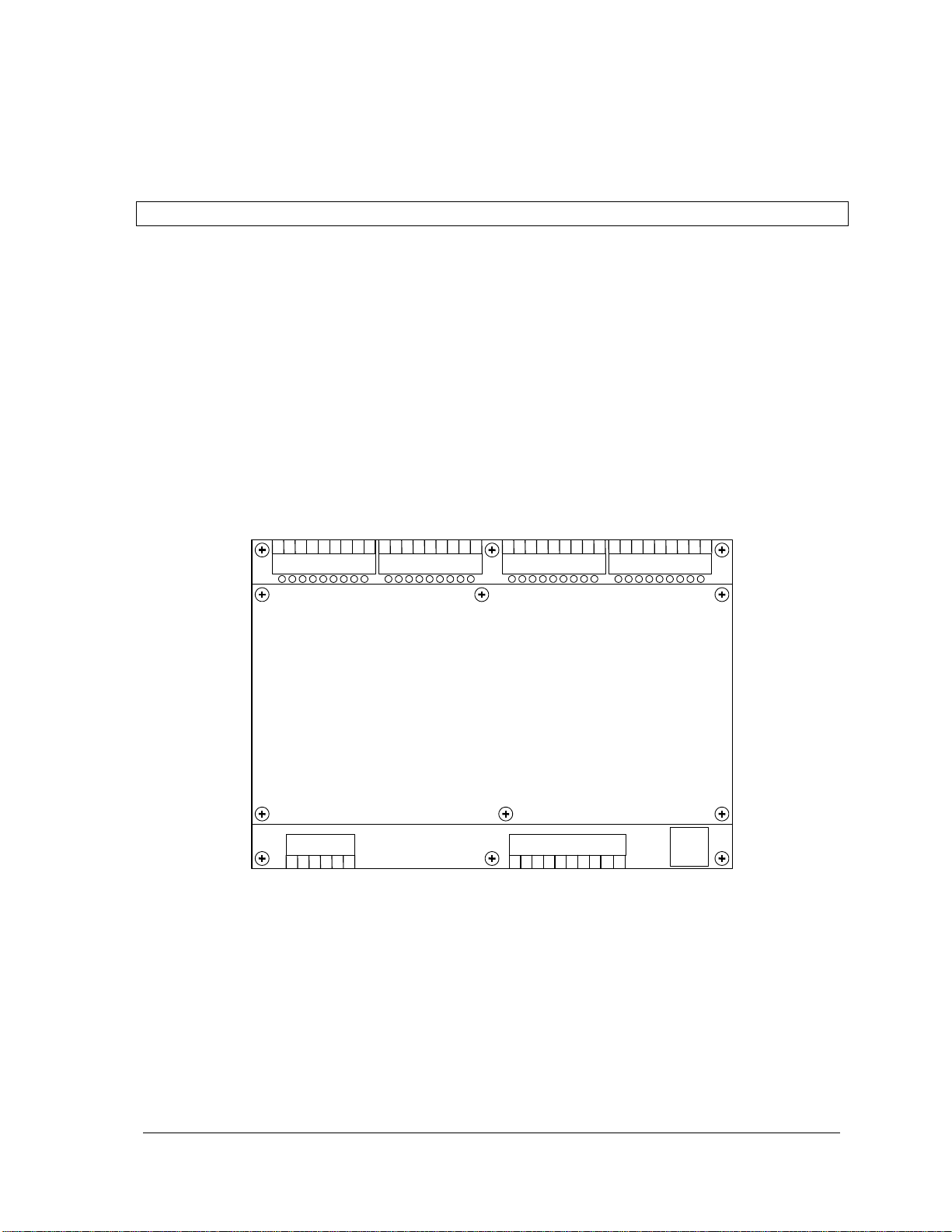
Digital I/O 24-31
Connector (P6)
Digital I/O 16-23
Connector (P7)
Digital I/O 8-15
Connector (P8)
Digital I/O 0-7
Connector (P9)
Power – Analog Out
Connector (P3)
Analog Inputs
Connector (P4)
RS-232 COM3
Connector (P5)
The 5604 I/O modules use screw termination style connectors for termination of field wiring. These
connectors accommodate solid or stranded wires from 12 to 22 AWG.
CAUTION: Remove power before servicing unit.
The 5604 I/O module has seven connectors for field wiring. Refer to Figure 1: 5604 I/O Module
Layout for connector locations.
Primary power input connections, VLOOP output power connection and optional analog output
connections are wired to a six-pole connector labeled P3. Refer to section 4-Power Supply for
details on wiring the power supply.
The nine analog inputs are wired to a ten-pole connector labeled P4. Refer to section 5-Analog
Inputs for details on wiring analog input signals.
The digital inputs and outputs are wired to four ten-pole connectors labeled P6, P7, P8 and P9.
Refer to section 7-Digital I/O for details on wiring digital input/output signals.
The 5604 I/O Module has one RS-232 serial communication port that is wired to a black 8 pin
modular RJ-45 connector labeled P5. Refer to section 8-Serial Communication for details.
Figure 1: 5604 I/O Module Layout
5604 Input/Output (I/O) Module - Hardware Manual
October 19, 2007
Page 9

8
4 Power Supply
4.1 Overview and Requirements
The 5604 I/O module requires 11-24Vdc applied to the AC/DC PWR IN terminals on connector P3
of the I/O board to power the analog input and optional analog output circuitry.
The current requirement of the analog portion (input and optional output circuitry) on the 5604 I/O
board can vary from a minimum of 10mA for basic operation of the analog circuitry to a maximum
of 550mA if all analog inputs, optional analog outputs and the 24V boost converter requires full
power to provide 6W (250mA @24V) of power.
The user has three options to supply 11-24V to the I/O board as outlined below but should
thoroughly examine the application and supply the 5604 I/O Module with a suitable power source.
Note: Voltage referred to as Vrms (or VAC on some products) indicates AC power. Voltage
referred to as V indicates DC power.
4.2 Power Supply Input Connections
Power to DC PWR on the I/O board can be provided in several ways:
With a 16Vac source supplying power to the controller board, 24V is available on the DC PWR
terminals on connector P5 of the controller board which can be used to power the lower I/O
model. See the section 4.2.1-Recommended AC Power Supply Configuration for details.
A 24Vdc source connected to the DC PWR terminals on the controller board and on the 5604
I/O module in a parallel configuration. See section 4.2.2-Recommended 24V Power Supply
Configuration for details.
With a 12Vdc source connected to the DC PWR terminals on the controller board and on the
5604 I/O module in a parallel configuration. See section 4.2.3-Recommended Battery
Configuration for a wiring example.
A 5103 UPS Power Supply supplies 5Vdc to the controller board through the IMC cable and
supplies 24Vdc to the 5604 I/O module through the 24Vdc output. See section 4.2.4Recommended 5103 Power Supply Configuration for an example of using the 5103 UPS Power
Supply.
CAUTION: Power can be applied to either the AC/DC power input OR the DC power input.
DO NOT apply power to both inputs. Damage to the power supply may result.
5604 Input/Output (I/O) Module - Hardware Manual
October 19, 2007
Page 10
9
4.2.1 Recommended AC Power Supply Configuration
120
Vrms
16
Vrms
Class 2
Transformer
AC/DC
PWR IN
DC PWR
+ –
1 2 3 4 5
6
P5
Controller Board
P3
5604 I/O Module
DC PWR
+ –
1 2 3 4 5
6
AOUT
0 1 COM
Vloop
+
Controller DC output
boosted to 24V
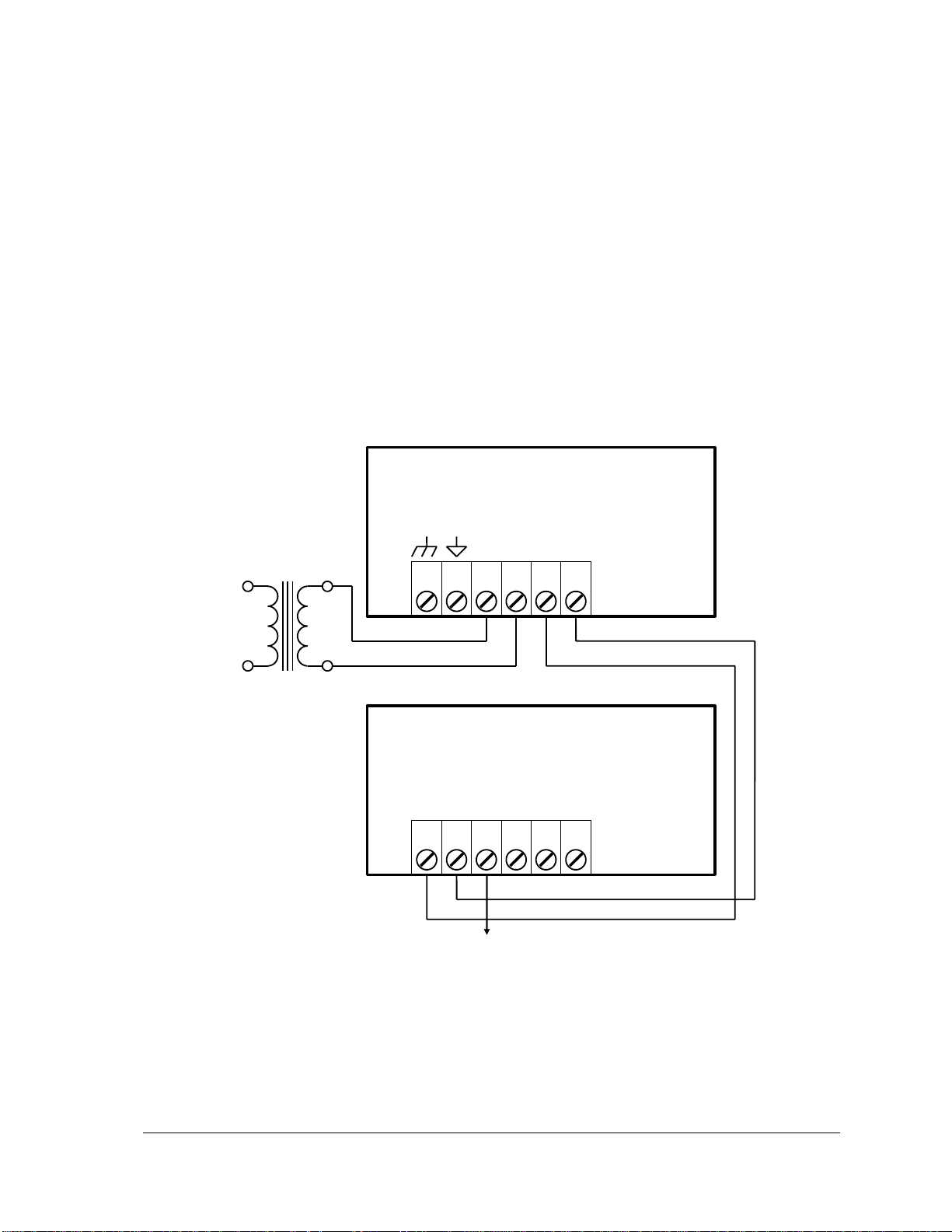
This configuration uses a single Class 2 16vac transformer to power the controller board and the
5604 I/O Module. 24V is available on the controller module connector P3. This is used to power the
analog circuitry for the analog input and output circuits on the 5604 I/O module.
Notes on this configuration:
The 24V-boosted output (VLOOP) can be switched on and off under the control of the
application program to save power to any loads connected to VLOOP.
The DC output of the controller board is unregulated and can be boosted to a stable 24Vdc on
the 5604 I/O Module under the control of the application program.
Only a limited amount of power is available from the controller. This configuration is not
recommended when a large amount of current is required at 24V.
The Controller Board DC Power terminal must be connected to the same power supply as the
5604 I/O Module DC Power terminals.
Figure 2: Recommended AC Power Supply Configuration
5604 Input/Output (I/O) Module - Hardware Manual
October 19, 2007
Page 11
10
4.2.2 Recommended 24V Power Supply Configuration
+
24Vdc Power
Supply
–
P3
5604 I/O Module
DC PWR
+ –
1 2 3 4 5
6
AOUT
0 1 COM
Vloop
+
AC/DC
PWR IN
DC PWR
+ –
1 2 3 4 5
6
P5
Controller Board
24V switched
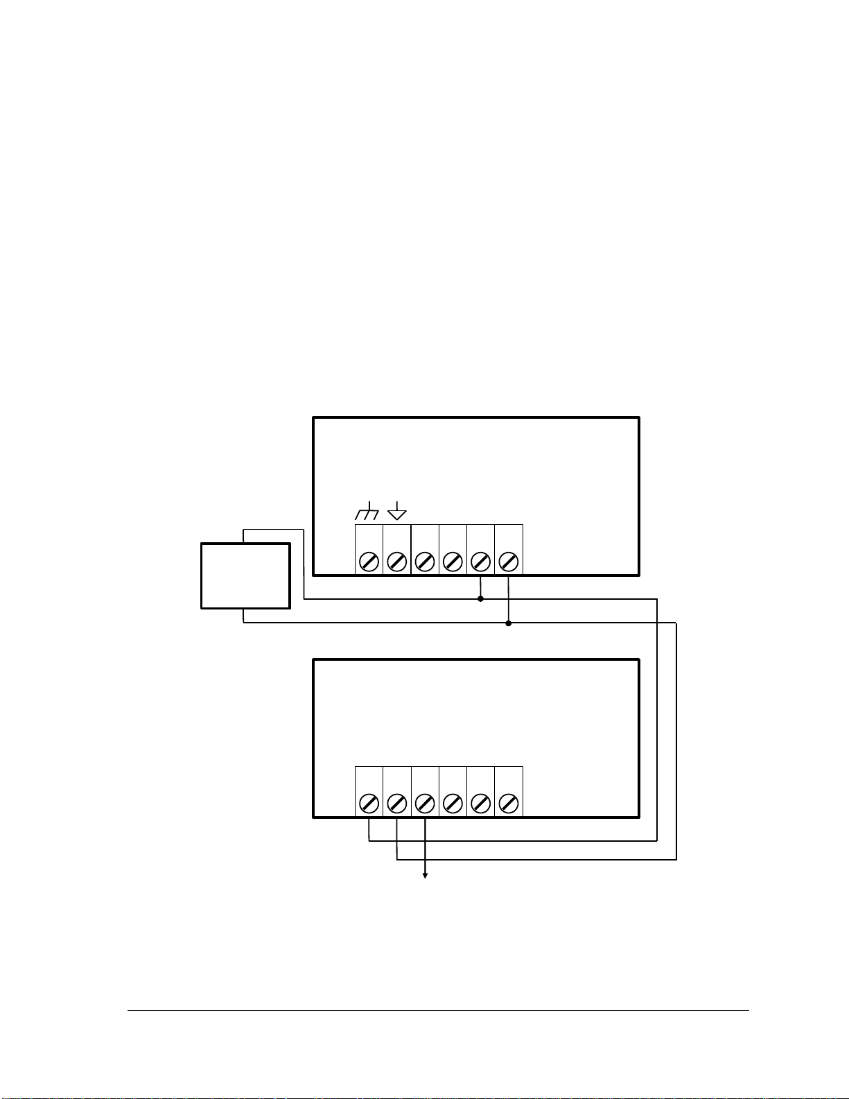
This configuration uses a 24V power supply to power the controller board and the 5604 I/O module.
This 24V is used to power the analog circuitry for the analog inputs and output circuits on the 5604
I/O module.
Notes on this configuration:
The 24V output (VLOOP) can be switched on and off under the control of the application
program to save power to any loads connected to VLOOP.
It is unnecessary to boost the 24V power in the 5604 I/O Module. The 24V output (VLOOP) on
the 5604 I/O Module can be switched under control of the application program.
This configuration is recommended when a large amount of current is required at 24V. Refer to
section 10-Specifications and the section outlining sample power calculations in the manual of
your respective controller board to determine the power required from the 24V power supply.
The Controller Board DC Power terminal must be connected to the same power supply as the
5604 I/O Module DC Power terminals.
Figure 3: Recommended 24V Power Supply Configuration
5604 Input/Output (I/O) Module - Hardware Manual
October 19, 2007
Page 12
11
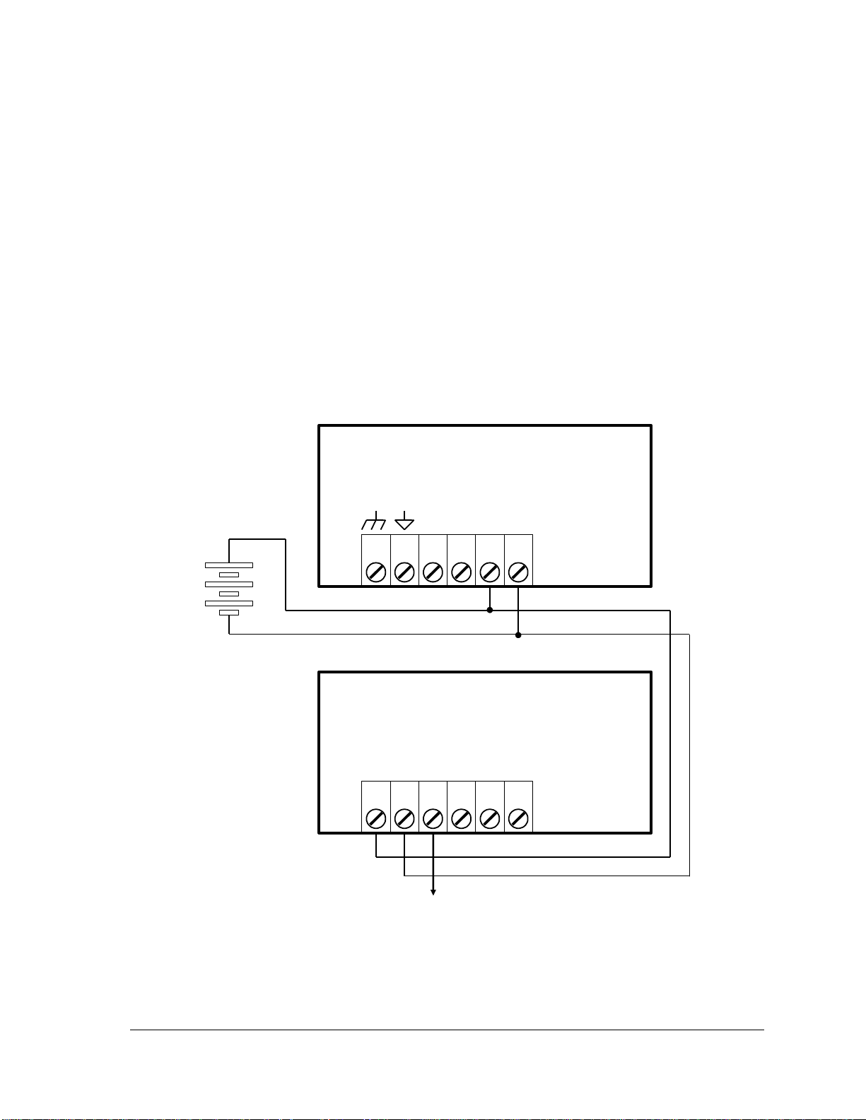
4.2.3 Recommended Battery Configuration
12V battery
P3
5604 I/O Module
DC PWR
+ –
1 2 3 4 5
6
AOUT
0 1 COM
Vloop
+
AC/DC
PWR IN
DC PWR
+ –
1 2 3 4 5
6
P5
Controller Board
12V boosted to 24V
This configuration uses a 12V battery to power the controller board and the 5604 I/O Module. This
12V is used to power the analog circuitry for the analog inputs and output circuits on the 5604 I/O
Module.
Notes on this configuration:
The 24V-boosted output (VLOOP) can be switched on and off under the control of the
application program to save power to any loads connected to VLOOP.
The DC input (battery voltage) to the 5604 I/O Module can be boosted to 24Vdc on the 5604 I/O
Module under the control of the application program.
This configuration is recommended when a large amount of current is required at 24V. Refer to
the specifications and the sample calculations to determine the power required from the 12V
battery.
The 5232 Controller Board DC Power terminal must be connected to the same power supply as
the 5604 I/O Module DC Power terminals.
Figure 4: Recommended Battery Configuration
5604 Input/Output (I/O) Module - Hardware Manual
October 19, 2007
Page 13
12
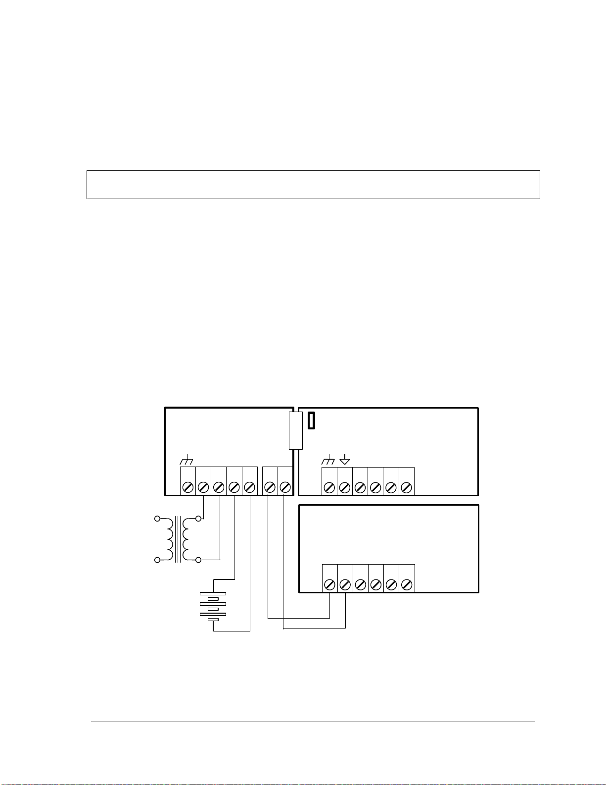
4.2.4 Recommended 5103 Power Supply Configuration
AC/DC
PWR IN
DC PWR
+ –
1 2 3 4 5
6
P5
Controller Board
1 2 3 4 5
9
10
P3
J5
5103 Power Supply
120
Vrm
24
Vrms
Class 2
Transformer
AC/DC
+ BATT
+ 24V
Optional 12 Volt
Gel Cel Battery
P3
5604 I/O Module
DC PWR
+ –
1 2 3 4 5
6
AOUT
0 1 COM
Vloop
+
When additional power is required by the system, 5000 Series 5103 power supplies can be used in
combination with the SCADAPack controllers. Refer to the System Configuration Guide for more
information.
The 5103 power supplies can be connected anywhere downstream (to the right) of the controller.
They will supply power to the modules downstream of them.
Note: The Sleep Mode feature of the controller applies only to those modules powered by the
controller.
The 5103 power supply may also be connected upstream (to the left) of any SCADAPack
Controller, but only if the following conditions are observed:
No power is applied to the power inputs of the controller board.
A jumper is installed at position J5 (see the user manual of your respective controller board for
details.
The sleep mode feature is not used.
This configuration uses a 5103 Power Supply module to power a SCADAPack controller. The
24VDC output from the 5103 powers the 5604 I/O module. The 5103 power supply provides a 5V
output to power the 5604 I/O module, the controller board and 5000 Series modules through the
IMC cables.
Note that no connection is made to the AC/DC PWR IN or DC PWR terminals on the controller
board.
Figure 5: Recommended 5103 Power Supply Configuration
5604 Input/Output (I/O) Module - Hardware Manual
October 19, 2007
Page 14
13
4.3 System Grounding
12V to 24V boost
ON/OFF
Dout 32
Dout 33
5305 Analog
Output Module
P3
+ –
DC PWR
1 2 3 4 5
6
0 1 COM
AOUT
+
Vloop
In most applications, it is desirable to ground the system by connecting the system power supply
common, to the chassis or panel ground.
On the 5604 I/O module, “-“ terminal of the 24V supply(DC PWR “-“) is already connected to the
enclosure by the printed circuit board traces.
4.4 Power Management Features
The 5604 I/O board provides a number of special features to reduce power consumption. These
power management features include:
VLoop power control.
12V to 24V DC/DC Converter Control.
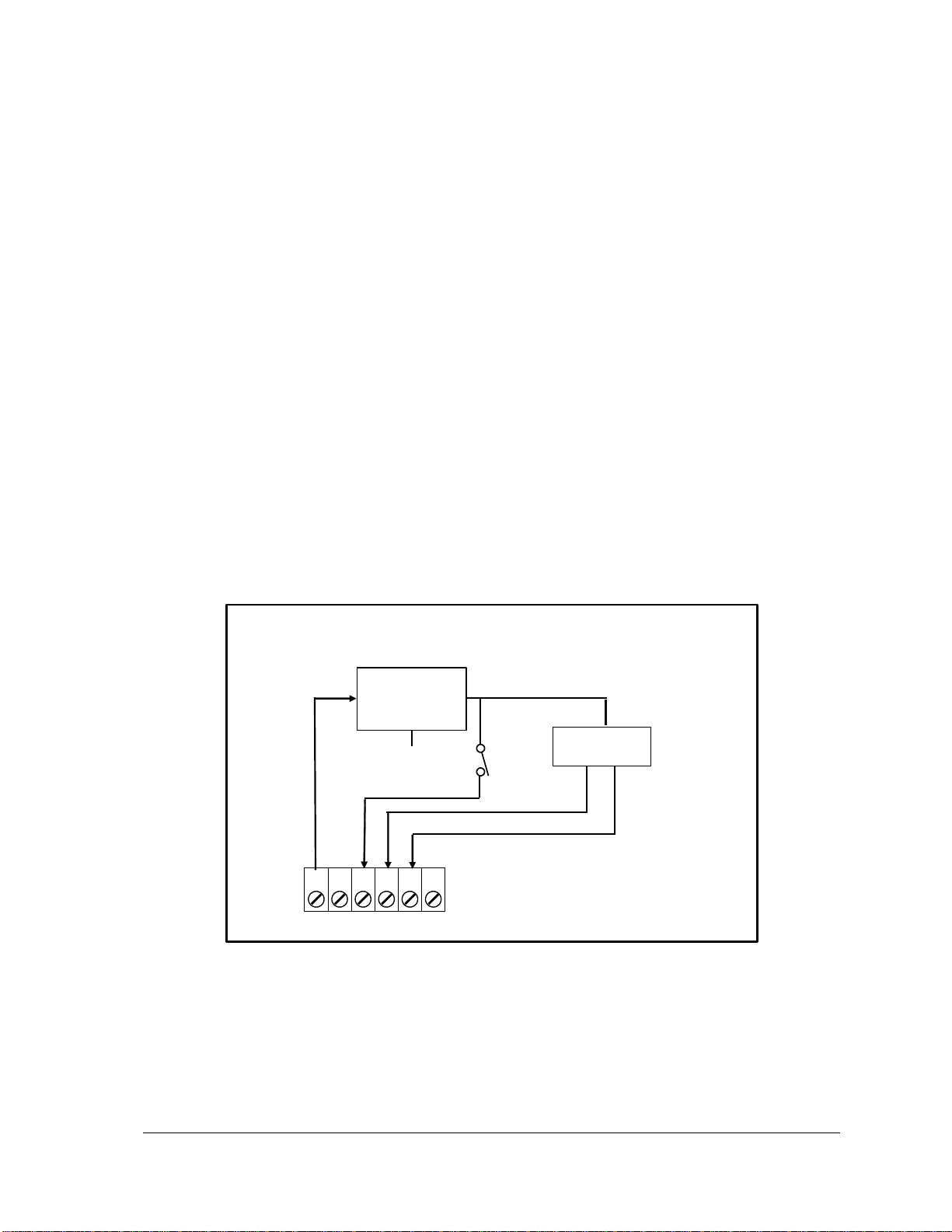
The 5604 I/O module provides two internal digital outputs that can be operated by the user
application to manage the power saving features. Internal digital outputs 32 and 33 and the power
management functions they control are described in the following sections.
Refer to Figure 6: Power Management for an overview of the power management features. Refer
to the appropriate software manual for information on using and controlling the internal Digital
Outputs. For TelePACE applications refer to the Register Assignment for the SCADAPack 5604 I/O
module and for ISaGRAF applications refer to the I/O Complex Equipment for SCADAPack 5604
I/O module.
Figure 6: Power Management
4.4.1 DC/DC Converter Control
The 12V to 24V DC/DC converter is used to provide 24 VDC for VLoop power and for the Analog
Output module. The converter should be turned on if the 5604 I/O Module is equipped with analog
5604 Input/Output (I/O) Module - Hardware Manual
October 19, 2007
Page 15

14
outputs for which 24V-drive capability is required. Otherwise, the DC/DC converter can be turned
off to conserve power.
Turn on Digital Output 32 to turn ON the 12V to 24V DC/DC converter. When the converter is
turned on 24Vdc is provided to the VLoop power and to the Analog Output module.
Turn off Digital Output 32 to turn OFF the 12V to 24V DC/DC converter. When the converter
is turned off VLoop power and the Analog Output module use is the applied input power.
Internal Digital Input 32 indicates the status of the 12V to 24V DC/DC converter. Digital Input 11
is set when the 12V to 24V DC/DC converter is on and is cleared when the 12V to 24V DC/DC
converter is off.
The 12V to 24V DC/DC converter is turned on when the LED power is enabled. This feature is
provided for service and diagnostics. Refer to the LED Power Control section in the hardware
manual of your respective controller board for further information on this feature
4.4.2 VLoop Power Control
The DC/DC converter output can be used to power analog input current loops or other
instrumentation. This output, VLoop, is controlled for intermittent or continuous operation. Turning
the VLoop output off when it is not required can save considerable electrical power.
The switched VLoop power source is the output of the DC-DC 12/24V converter if it is turned on.
See the DC/DC Converter Control section for converter information. The VLoop power source is
the applied input power if the DC-DC converter is turned off.
Turn on Digital Output 33 to turn ON the VLoop output.
Turn off Digital Output 33 to turn OFF the VLoop output.
Note: When VLoop is first turned on, the user application program must wait at least one second
for input readings to stabilize. This time may be increased depending on field sensors and
transmitters. Documentation for these devices should be consulted.
The VLoop output is turned on when the LED power is enabled. This feature is provided for service
and diagnostics. Refer to the LED Power Control section in the hardware manual of your respective
controller board for further information.
4.4.3 VLoop Over-Current Protection
When VLoop output is turned on, it is monitored for excessive current consumption caused by field
wiring or instrumentation problems. If sustained over-current is detected (100 ms), VLoop is turned
off even though internal Digital Output 33 is turned on. This protection prevents unnecessary fuse
blowing, circuitry damage and rapid battery depletion.
When VLoop output is turned on, using internal Digital Output 33, and a short circuit is detected
VLoop will turn off. VLoop will turn on to try again 5 seconds after turning off. If the fault
condition still exits VLoop will again turn off and retry after a 5 second delay. While the fault
condition exists internal Digital Input 34 will be ON.
5604 Input/Output (I/O) Module - Hardware Manual
October 19, 2007
Page 16

15
5 Analog Inputs
The 5604 I/O module enhances the capacity of a SCADAPack controller by providing an additional
nine single ended analog inputs on connector P4, that can be configured for current or voltage mode.
Refer to Figure 1: 5604 I/O Module Layout for the location of this connector.
Analog Inputs 0-7 can be configured for current or voltage mode using jumper switches. Please refer
to section 5-Analog Inputs on how to select input modes.
In voltage mode, these analog inputs are single ended and the measurement range is 0-10V. The
range is selected via the configuration DIP switches. Refer to section 5.2- Range and
Resolution below for details.
In current mode, a 250 current sense resistor appears across each analog input channel.
Measurement range in current mode is 0-20mA or 4-20mA selectable via the configuration
switches. The 250 resistor produces a voltage drop (input reading) of 5V for a 20mA of
current flow.
All analog input channels are transient protected, optically isolated from the main logic supply and
share a common return (COM) that is connected to the chassis.
The controller uses a 16-bit successive approximation analog to digital (A/D) converter and provides
15 bit resolution over the range of the analog input.
Analog Input 8 is a 0 to 32.768-volt input that measures with 10-bit resolution and can be used to
monitor a power supply or battery voltage.
There is one internal analog input that is used in application programs to monitor the DC/DC
converter voltage used for VLOOP.
For TelePACE applications use the SCADAPack 5604 I/O Module register assignment to read
the nine external and the internal analog inputs.
For ISaGRAF applications use the sp5604 I/O connection to read the nine external and the
internal analog inputs.
Please refer to the respective TelePACE and ISaGRAF software manuals on how to assign the above
registers to read these input ports.
5.1 Current or Voltage Mode
Analog Inputs 0-7on connector P4 can be configured for either voltage or current mode using
jumper links. The jumper links reside on the lower I/O board itself. To access the jumper links, the
main cover and controller board will have to be taken off by removing the retaining screws.
Note: Analog Input channels 0-7 are configured for current mode by default.
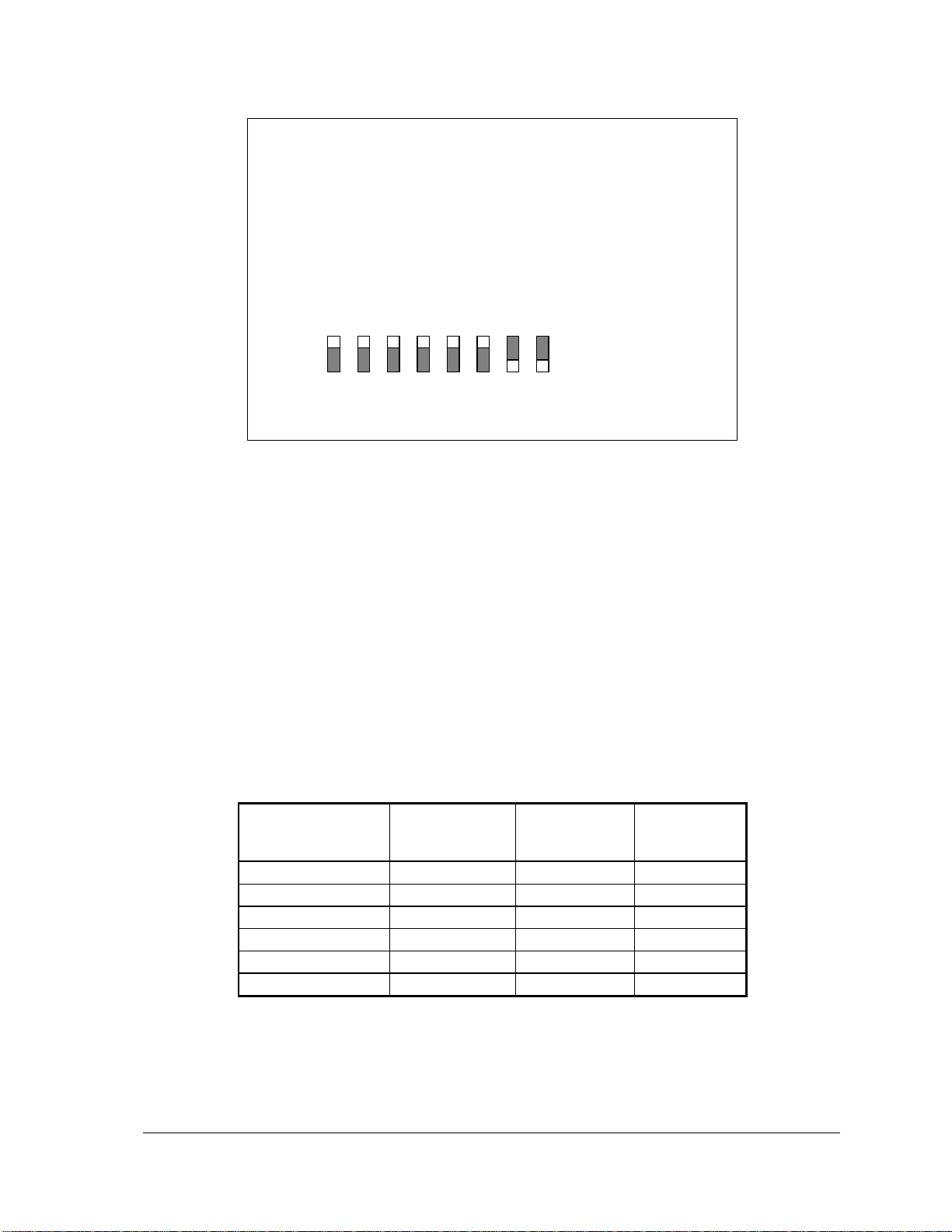
To select current mode, install the jumpers on the side labeled 20mA on the I/O board as shown in
the figure below for analog inputs 0-5. In current mode a 250 resistor appears across the input
channel.
5604 Input/Output (I/O) Module - Hardware Manual
October 19, 2007
Page 17
16
5V
AIN0
20mA
J10
AIN1
J11
AIN2
J12
AIN3
J13
AIN4
J14
AIN5
J15
AIN6
J16
AIN7
J17
Current (mA)
Channel 0-7
Voltage (V)
Channel 0-7
Voltage (V)
Channel 8
A/D Output
0
0V
0V 0 1.22mA
0.305mV
NA 1 4
1.0
3.277
3277
10
2.5
8.192
8192
20
5.0
16.38
16384
39.999
9.9997
32.767
32767
Figure 7: Analog Input Mode Settings
To select voltage mode, install the jumpers on the side labeled 5V. In the figure above, Analog
inputs 6 and 7 are configured for voltage mode.
5.2 Range and Resolution
Analog inputs channels 0 – 7 use a16-bit, unipolar, analog to digital (A/D) converter that measures
input voltages from 0 to 10V or currents from 0-20mA. In voltage mode, the input is represented by
a 15 bit unsigned real number. In current mode, the input is represented by a 14 bits unsigned real
number
Input resolution for channels 0-7 is:
0.305mV/count in voltage mode
1.22µA/count in current mode. There is 100% over range.
The following table shows the typical A/D output value for several input signals.
Analog input 8 is configured for voltage mode only. Voltage ranges of up to 32.768V are
measurable using a 10 bit A/D converter and represented with 15 bits of data. The input resolution
on this channel approximately 0.03V/count.
5604 Input/Output (I/O) Module - Hardware Manual
October 19, 2007
Page 18

17
5.3 Wiring
The analog inputs support loop powered and self powered transmitters. Loop powered transmitters
are two terminal devices that connect between a power supply and the analog input. The loop
current continues from the power supply, through the transmitter and to ground through a 250
resistor built into the 20mA input circuit. Self-powered transmitters have three terminals called
power in, signal out and common. Self-powered transmitters can have a current or voltage output.
The signal out connects to the Analog Input Channel, the common connects to GND and the power
in connects to a power supply.
There are three options for the user when selecting the power source. In all cases it is important for
the user to ensure that the transmitter has enough voltage for proper operation. The transmitter
manufacturer supplies the minimum operating voltage specification of the transmitter. The analog
input requires a minimum of 5V.
The first option is to use the 5604 I/O Module VLOOP Supply that boosts the input voltage to 24V
with a 12V to 24V DC/DC converter. The stepped up voltage is available on connector P3 and is
labeled VLOOP. There is sufficient power available for the eight analog inputs and four analog
outputs all operating at 20mA. Significant power saving is possible by switching the VLOOP supply
off when measurements are not being made.
The second option is similar to the first except that the power supply is not boosted up to 24V. This
can be used with low voltage transmitters or when the input voltage is sufficiently high that further
boosting is not necessary. It is still possible to switch the supply off under program control. When
the step up is turned off, VLOOP is approximately 0.5V less that the power input voltage.
5.3.1 Wiring Examples
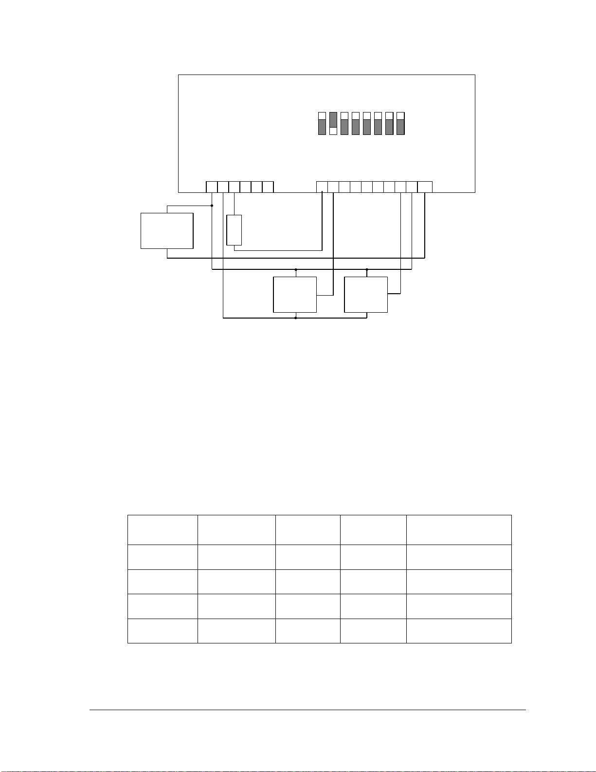
Several wiring examples for loop and self powered transmitters are illustrated in Figure 8: Analog
Input Wiring. The transmitters are wired as follows:
Channel 0 has a loop powered current transmitter connected to VLOOP.
Channel 1 has a self-powered voltage transmitter connected to the external power supply.
Channels 2 through 6 are unused.
Channel 7 has a self-powered current transmitter connected to the external power supply.
Channel 8 is used to monitor the external power supply.
If a 12V external power supply or battery is used the application can boost this voltage to 24V at
VLOOP using the internal DC/DC converter. If a 24V external power supply is used it is
unnecessary to boost this voltage.
5604 Input/Output (I/O) Module - Hardware Manual
October 19, 2007
Page 19
18
+
External 12 or
24Vdc Power
Supply
_
Voltage
8
+
_
+Vdc – Vloop 0 1 GND
7 6 5 4 3 2 1
0 1 2 3 4 5 6 7 8 GND
Current
P4 - Analog Inputs
PWR
Voltage O/P
COM
PWR
Current O/P
COM
J1 J2 J3 J4 J5 J6 J7 J8
9
10 6 5 4 3 2 1
P3 – Power and Analog Outputs
Filter
Setting
Response
Time
Digital
Output 35
Digital
Output 34
< 3 Hz
155ms at 60Hz
185ms at 50Hz
OFF
OFF
Maximum filter setting
6 Hz
85ms at 60Hz
85ms at 50Hz
OFF
ON
Medium filter setting
11 Hz
45ms at 60Hz
55ms at 50Hz
ON
OFF
Minimum filter setting
30 Hz
30ms at 60Hz
30ms at 50Hz
ON
ON
No filter
Figure 8: Analog Input Wiring
5.4 Filtering and Response Timing
The 5604 I/O Module also provides internal digital outputs to control the filtering and response
times of the analog to digital conversion. Theses digital outputs can be controlled by the user
application to either maximize the filtering in noisy environments or minimize the filtering in
applications that require the fastest response times.
The following chart shows the response timing for the selectable filter settings.
Internal digital outputs 34 and 35 control the filter setting.
The 5604 I/O module may select 50 or 60 Hz line frequency for digital and analog input processing.
The Controller board Option Switch 3 selects the line frequency option.
5604 Input/Output (I/O) Module - Hardware Manual
October 19, 2007
Page 20
19
6 Analog Outputs
+
External 12 or
24Vdc Power
Supply
_
L
O
A
D
+Vdc – Vloop 0 1 GND
6 5 4 3 2
1
P3 – Power and Analog Outputs
DC/DC
boost converter
24Vdc output
Aout0
Aout1
L
O
A
D
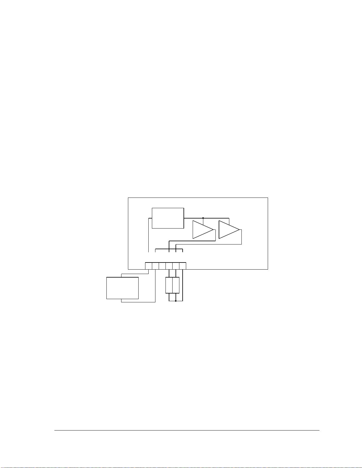
The 5604 I/O Module may include two channels of analog output if this option was requested at
time of purchase.
For TelePACE applications use the SCADAPack AOUT I/O Module register assignment to
write to the two analog outputs.
For ISaGRAF applications use the aout2pt I/O connection to write to the two analog outputs.
Please refer to the respective TelePACE and ISaGRAF software manuals on how to assign the above
registers to read these input ports.
6.1 Current Outputs
The 5604 I/O Module can be equipped with an optional 5305 Analog Output Module that provides
two 20mA analog outputs. Analog output resolution is 12 bits. The outputs are transient and over
voltage protected. The outputs share a common return (GND) with each other and the 5604 I/O
Module analog inputs.
The 12V to 24V DC/DC boost converter powers the analog outputs. The boost converter is used to
boost the DC input power to 24V. The application program may control the boost converter.
Figure 9: Analog Output Wiring
5604 Input/Output (I/O) Module - Hardware Manual
October 19, 2007
Page 21
20
6.2 Voltage Outputs
Resistance
Output Range
Voltage Range
250
0-20mA
0 to 5V
500
0-20mA
0 to 10V
Raw Count
Current
(0% offset)
Current
(20% offset)
0
0 mA
4 mA
8
4.88 µA
4 mA
1500
0.92 mA
4.73 mA
3200
1.95 mA
5.56mA
6552
4 mA
7.2 mA
7000
4.27 mA
7.42 mA
10000
6.11 mA
8.88 mA
16384
10 mA
12 mA
24576
15 mA
16 mA
32760
19.995 mA
19.995 mA
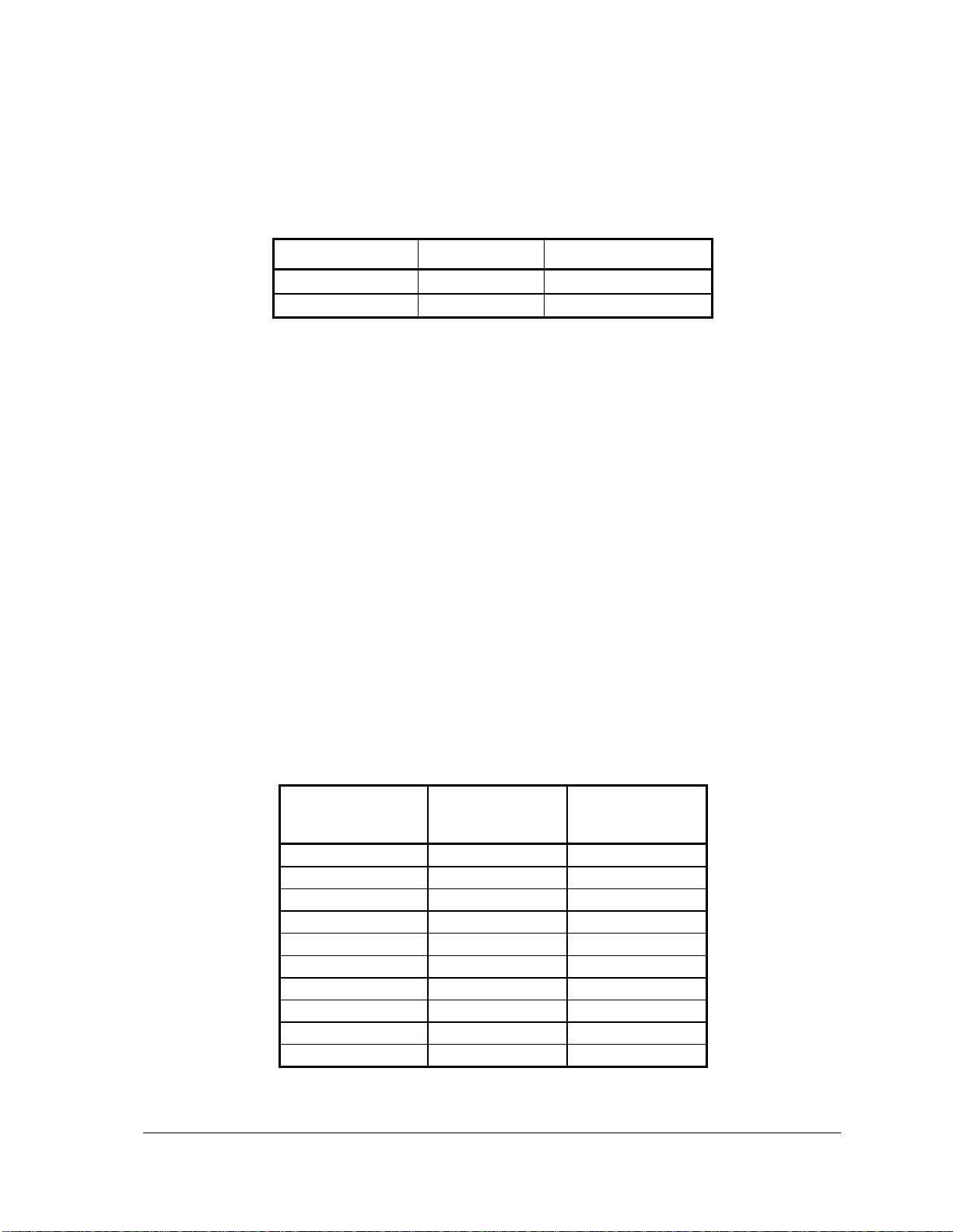
To obtain voltage outputs, connect a load resistor as shown in Figure 9: Analog Output Wiring
above. Connect the voltage device across the load resistor. The table below list resistance values and
output range settings for common voltage ranges. The resistance value listed is the parallel
resistance of the device and the load resistor.
6.3 Range and Resolution
The optional analog output module installed on the 5604 I/O Module has a 12-bit, unipolar, digital
to analog (D/A) converter. These analog outputs can be configured for a 0% (0-20mA) or 20% (420mA) range. There are 4096 D/A counts in the output signal range and one D/A count represents a
value of 8 raw counts. Raw counts are displayed or issued from the application program.
The 0-20mA output range resolution is 4.88µA/count, such that 8 raw counts represent 4.88 µA.
For a 0% offset, use the following relationship to determine the output current based on your raw
counts:
Output Current [mA] = (20 * Raw Count) / 32760
For a 20% offset, use the following relationship:
Output Current [mA] = ( (16 * Raw Count) / 32760 ) + 4
The table below shows the output current for several raw counts, when the analog output is
configured for a 0% and 20% offset.
5604 Input/Output (I/O) Module - Hardware Manual
October 19, 2007
Page 22

21
7 Digital I/O
The 5604 I/O module has 32 universal digital inputs/outputs. Each digital I/O point can be used as
an input or an output only. The inputs can be used to monitor the status of that output.
The 32 I/O points are organized into four groups of eight. Four connectors are used for wiring the
digital inputs/outputs. These connectors are identified as P6 through P9. Refer to figure_37Figure
1: 5604 I/O Module Layout for the location of these connectors.
In addition to the 32 universal digital input/outputs there are 3 internal digital inputs and 2 internal
digital outputs that are used to monitor and control the DC/DC converter or VLOOP power supply
as well as to monitor digital output mismatch status. Refer to section 7.3-Internal DIO for
information on these internal digital I/O.
For TelePACE applications use the SCADAPack 5604 I/O Module register assignment to read
the digital inputs and write the digital outputs.
For ISaGRAF applications use the sp5604 I/O connection to read digital inputs and write the
digital outputs.
Please refer to the respective TelePACE and ISaGRAF software manuals on how to assign the above
registers to read these input ports.
7.1 Digital Inputs
The inputs are intended for use with dry contacts such as switches, open collector transistors and
relay contacts. Wetting current for the contacts is provided. The input is connected from the I/O
terminal to the terminal labeled GND. All GND terminals are connected internally to the
SCADAPack chassis.
If LED power is enabled, there is a continuous 5mA wetting current for each input. Indicator LED’s
will be at their maximum brilliance if on. This facilitates field service and diagnostics.
If LED power is disabled then the wetting current is turned on only when the digital inputs are
scanned. Power consumption is reduced as the inputs are scanned only once every millisecond.
Indicator LED’s are dim in this condition. This is normal.
7.2 Digital Outputs
Outputs are open-collector/open drain type for use with sustained DC loads of up to 1 ampere.
Loads with high in-rush currents may exceed the 1A rating. The output circuit will tolerate these
higher peak currents. The load is connected between this output point and a +DC power source. The
negative side of the DC power source must be connected the terminal labeled GND. All GND
terminals are connected internally to the SCADAPack chassis. This is the return path from –DC to
the load.
Inductive load transient suppression is built into each digital output point. It is not necessary to add
additional inductive load transient suppression unless highly inductive loads (greater than 1H) are
operated continuously at greater than 0.5Hz.
7.3 Internal DIO
The 5604 I/O Module also provides internal digital outputs to enable the DC/DC boost converter, to
switch on/off the boost converter output and control the analog input filtering. Theses digital outputs
can be controlled by the user application to manage power savings and control the analog input
response.
5604 Input/Output (I/O) Module - Hardware Manual
October 19, 2007
Page 23

22
Digital input 32 returns the DC/DC converter status.
0 = DC/DC converter off
1 = DC/DC converter on
Digital input 33 returns the DC/DC converter over current status.
0 = Over current not detected
1 = Over current detected
Digital input 34 returns the digital output mismatch status.
0 = No mismatch
1 = One or more digital outputs mismatch
Digital Output 32 is used to control the DC/DC converter.
0 = DC/DC converter off
1 = DC/DC converter on
The 12V to 24V DC/DC converter is turned on when the
LED power is enabled. This feature is provided for service
and diagnostics.
Digital Output 33 is used to control the VLoop power supply.
0 = VLoop output off
1 = VLoop output on
The VLOOP output is turned on when the LED power is
enabled. This feature is provided for service and
diagnostics.
Digital Outputs 34 and 35 control the SCADAPack 5604 I/O Module Analog Input
filters.
Filter Setting Digital Output 35 Digital Output 34
< 3 Hz OFF OFF
6 Hz OFF ON
11 Hz ON OFF
30 Hz ON ON
5604 Input/Output (I/O) Module - Hardware Manual
October 19, 2007
Page 24
23
7.4 Wiring Examples
8 7 6 5 4 3 2
1
GND 7 6 5 4 3 2 1 0
P9 – Digital I/O 0-7
+ 24V Load –
P7 and P8 – Digital I/O 8-23 not shown.
9
+
12Vdc Power
Supply
_
+
24Vdc Power
Supply
_
+ 12V Load –
8 7 6 5 4 3 2
1
GND 31 30 29 28 27 26 25 24
P6 – Digital I/O 24-31
9
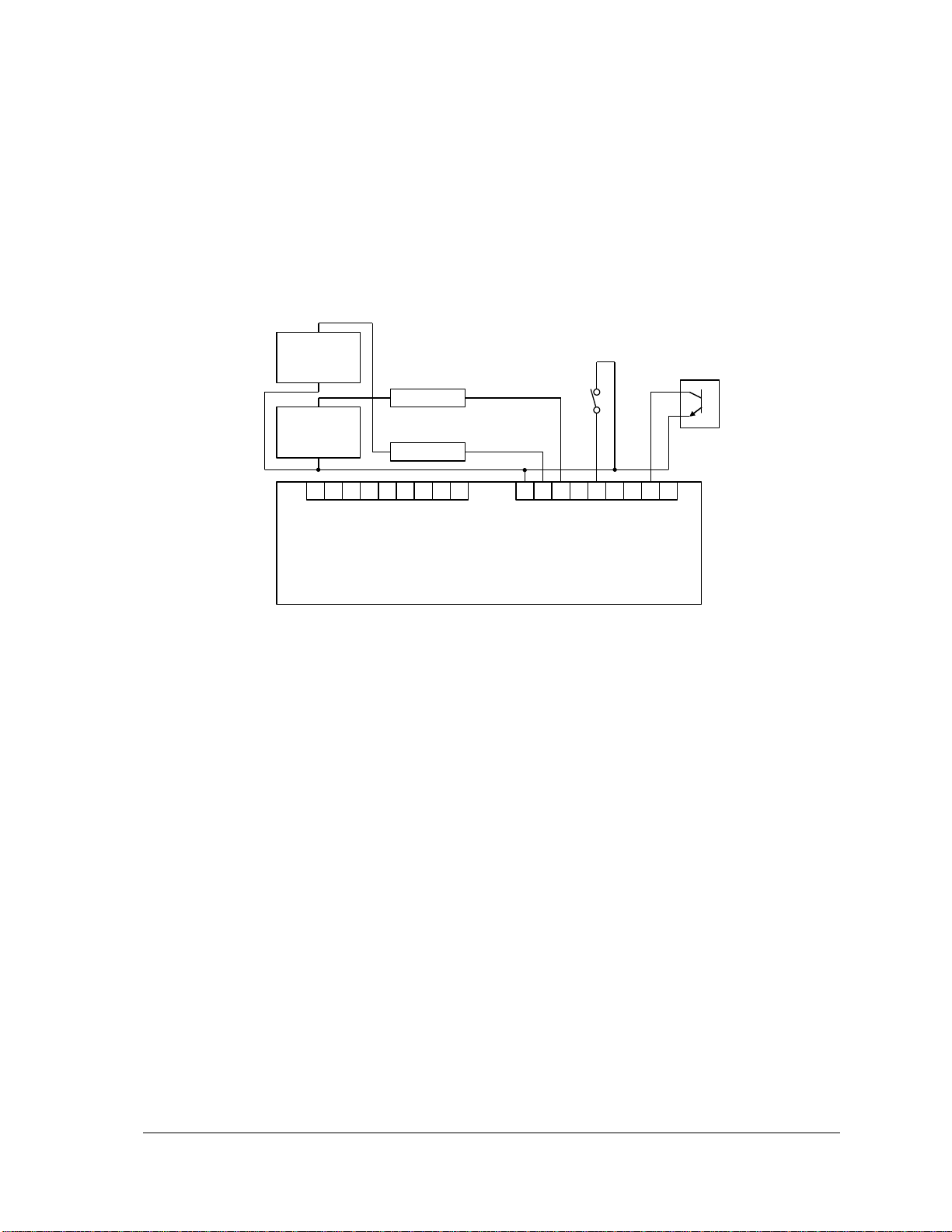
Various I/O point wiring examples are shown in Figure 10: Digital Input/ Output Wiring below.
Inputs and outputs can be used on any of the I/O points.
Digital I/O point 7 is shown connected to a 12V load and external 12V-power supply.
Digital I/O point 6 is shown connected to a 24V load and external 24V-power supply.
Digital I/O point 4 is shown monitoring a dry contact.
Digital I/O point 1 is shown monitoring an open collector contact.
Figure 10: Digital Input/ Output Wiring
5604 Input/Output (I/O) Module - Hardware Manual
October 19, 2007
Page 25
24
8 Serial Communication
Port
Type
Description
COM3
RS-232
RJ-45 connector designated P5 on the 5604 I/O Module.
Parameter
Supported Values
Baud Rate
1200, 2400, 4800, 9600, 19200, 38400, 57600 and
115200.
Default: 9600
Duplex
Half
Default: Half
Parity
Odd, None or Even
Default: None
Data Bits
7 or 8 Bits
Default: 8 Bits
Stop Bits
1 or 2 Bits
Default: 1 Bit
Receive Flow Control
ModbusRTU or None
Default: ModbusRTU
Transmit Flow Control
Ignore CTS or None
Default: None
Station
1 to 65534
Default: 1
Protocol
None, Modbus RTU, Modbus ASCII and optionally
DF1 Or DNP.
Default: Modbus RTU
Addressing Mode
Standard or Extended
Default: Standard
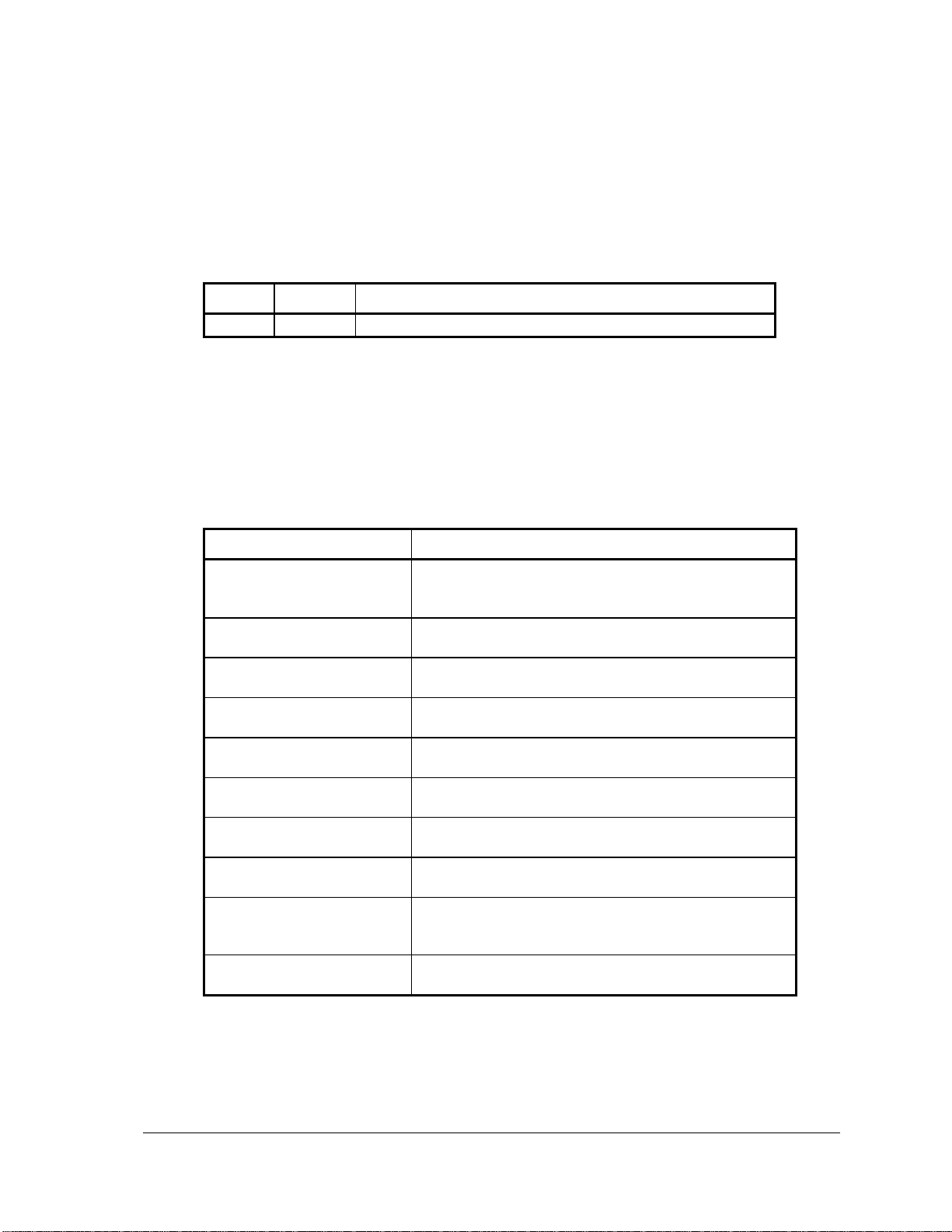
The 5604 I/O module enhances the serial communication ability of a SCADAPack controller by
providing an additional RS-232 serial port identified as COM3. The RS-232 port is an 8-pin female
RJ-45 connector configured as Data Terminal Equipment (DTE) and only supports a half-duplex
serial communication. The recommended specification for RS-232 cable length is a maximum of 50
feet or 15.2 meters. Shielded cable must be used and the shield should be connected to chassis
ground at one end.
8.1 COM3 RS-232 Serial Port
Connections to COM3 are made through a RJ-45. The wiring and pin connections for this connector
are described in the section 8.2- RJ-45 Modular Connector for RS-232.
The following table shows the serial and protocol communication parameters supported by COM1.
These parameters are set from TelePACE, ISaGRAF Workbench or from an application program
running in the controller. Default values are set when a Cold Boot or Service Boot is performed on
the controller.
8.2 RJ-45 Modular Connector for RS-232
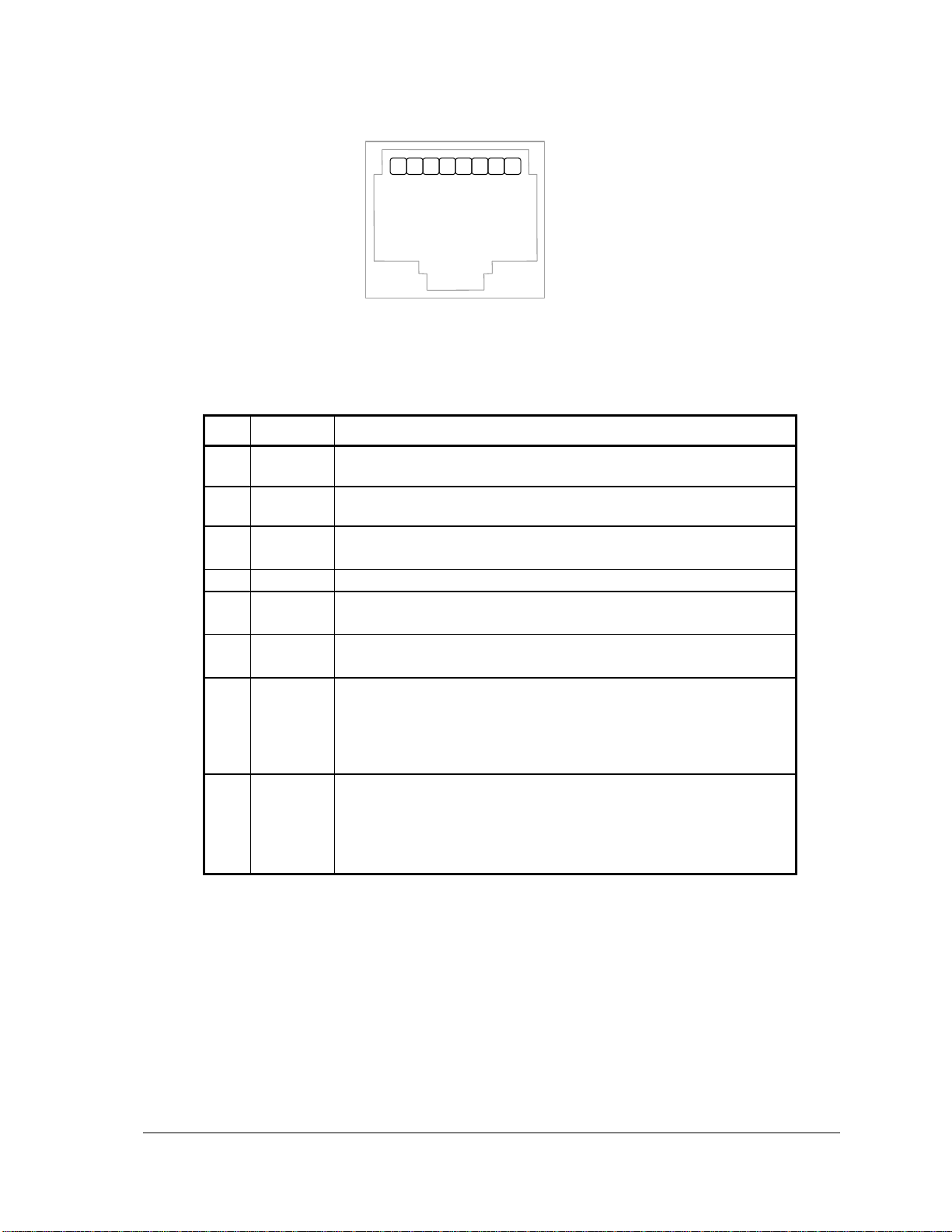
Serial communication port COM3 on the 5604 I/O module uses an 8-pin female RJ-45 connectors
configured as Data Terminal Equipment (DTE). The following diagram shows the pin connections
for the RS-232 (RJ-45) port connector for COM3.
5604 Input/Output (I/O) Module - Hardware Manual
October 19, 2007
Page 26
25
RJ-45 Modular Jack
1. +5V
2. DCD
3. DTR
4. GND
5. RxD
6. TxD
7. CTS
8. RTS
2187654
3
Pin
Function
Description
1
5V
(Output)
This pin can be connected to the 5V power supply by installing a
jumper at J4 on the SCADAPack controller board.
2
DCD
(Input)
The DCD led is on for a MARK level.
3
DTR
(Output)
This pin is normally at a MARK level.
This pin is at a SPACE level when DTR is de-asserted.
4
GND
This pin is connected to the system ground.
5
RxD
(Input)
The level is SPACE on standby and MARK for received data.
The LED is lit for a MARK level.
6
TxD
(Output)
The level is SPACE on standby and MARK for transmitted data.
The LED is lit for a MARK level.
7
CTS
(Input)
This level must be a MARK for the communication port to
transmit data. When the attached device does not provide this
signal, the controller keeps the line at a MARK.
When the attached device does provide this signal, it must set
CTS to MARK to allow the controller to transmit data.
8
RTS
(Output)
This pin is a MARK if full-duplex operation is selected for the
port.
This pin is set to a MARK just before and during transmission of
data if half-duplex operation is selected.
This pin is set to a SPACE when no data is being transmitted.
Figure 11: Front View of an RJ-45 Connector
The following table provides a description of the function of each pin of the RJ-45 connector. In this
table a MARK level is a voltage of +3V or greater and a SPACE level is a voltage of –3V or less.
8.3 RS-232 Wiring Examples
See the chapter on Serial Communications in the hardware manual of your respective controller
board for wiring examples.
8.4 RS-232 Cables
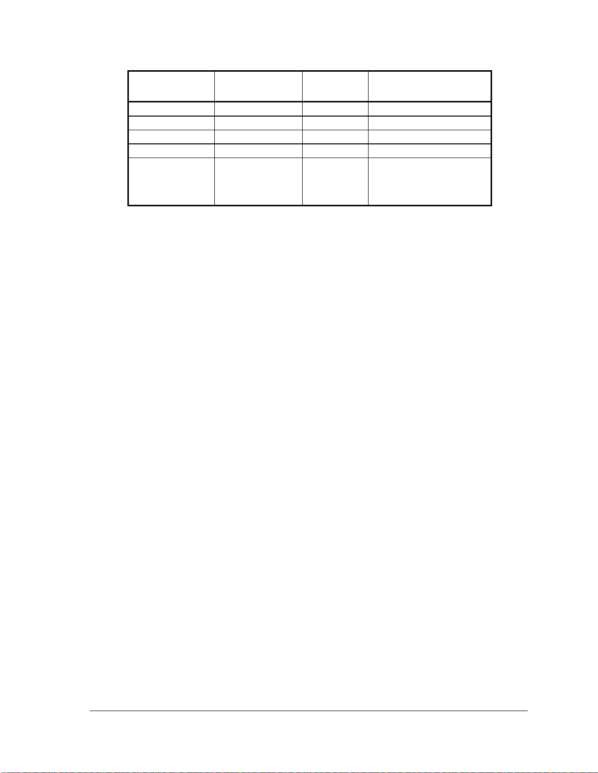
8.4.1 RJ-45 to DE-9S DTE
This cable is used to connect from an RJ-45 based RS-232 port on the 5604 I/O module to a DE-9P
connector on a DTE such as a PC. A 10 ft. long cable is available from Control Microsystems as
part number 297217.
5604 Input/Output (I/O) Module - Hardware Manual
October 19, 2007
Page 27
5604 Input/Output (I/O) Module - Hardware Manual
26
RJ-45
8 Pins
DTE Function
DE9S DTE
Function
DE9S
Shield connects to shell
6
TxD
RxD
2 5 RxD
TxD
3 4 GND
GND
5
1, 2, 3, 7 and 8
are not
connected at this
end.
GND
GND
No wires connected at
this end.
October 19, 2007
Page 28
27
8.4.2 RJ-45 to DE-9P DCE
RJ-45
DTE Function
DE-9P DCE
Function
DE-9P
Shield connects to shell
3
DTR
DTR
4 6 TxD
TxD
3 5 RxD
RxD
2 2 DCD
DCD
1 4 GND
GND
5 7 CTS
CTS
8 8 RTS
RTS
7 1 +5V
+5V
9
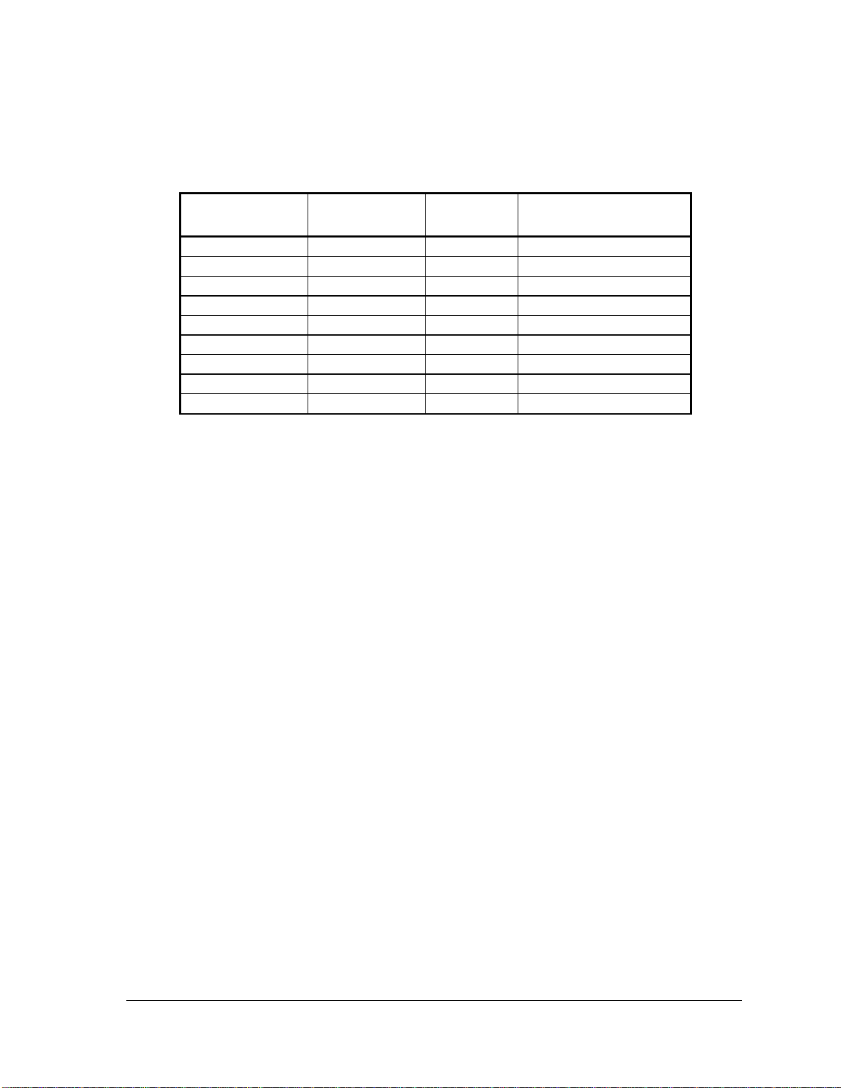
This cable is used to connect from an RJ-45 based RS-232 port on the SCADAPack P1A controller
to DE-9S connector on a DCE such as a modem. A 15-inch long cable is available from Control
Microsystems as part number 297218.
5604 Input/Output (I/O) Module - Hardware Manual
October 19, 2007
Page 29
28
9 Operation
LED
Function
RX
On when receiving data COM3.
TX
On when transmitting data on COM3.
CTS
On when CTS is asserted on COM3.
DCD
On when DCD is asserted on COM3.
DI/O
On when the corresponding input is on.
On when the corresponding output is
on.
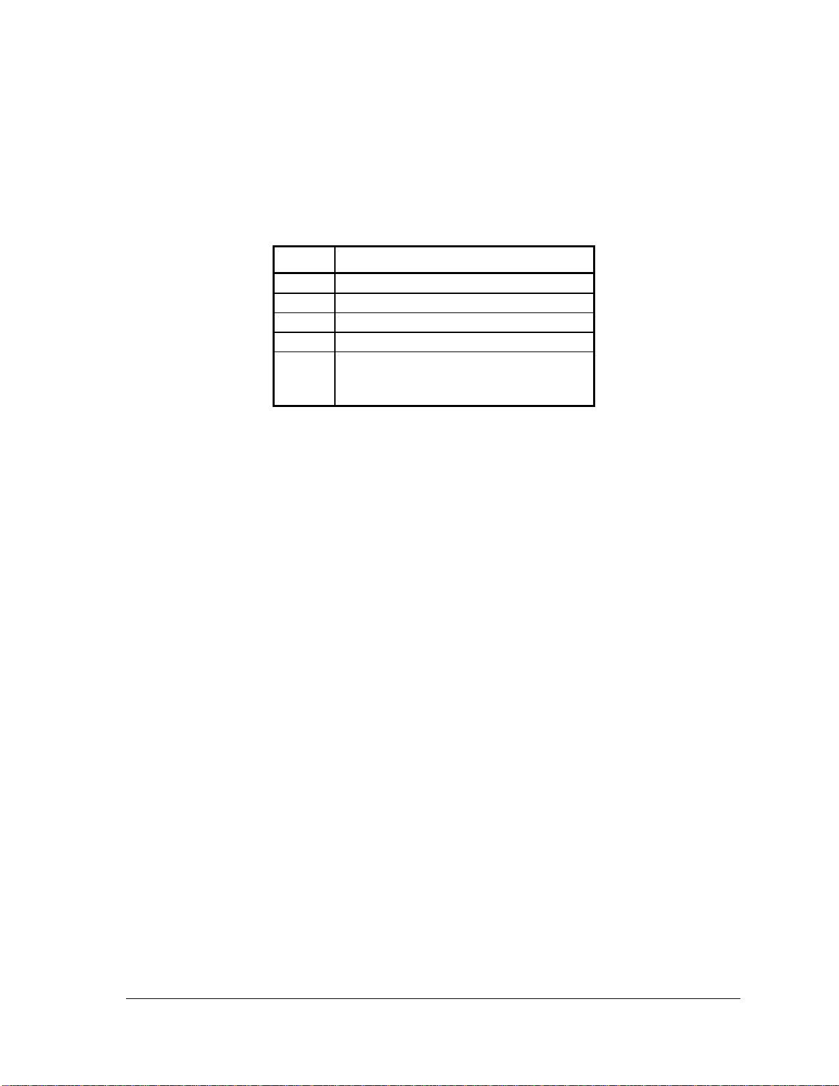
9.1 LED Indicators
This I/O module provides an additional 36 LEDs. All LED’s can be disabled by the controller board
to conserve power. Refer to the chapter on LED Indicators in the hardware manual of your
respective controller board for details. The table below describes some of the LEDs on the 5604
I/O module.
5604 Input/Output (I/O) Module - Hardware Manual
October 19, 2007
Page 30
29
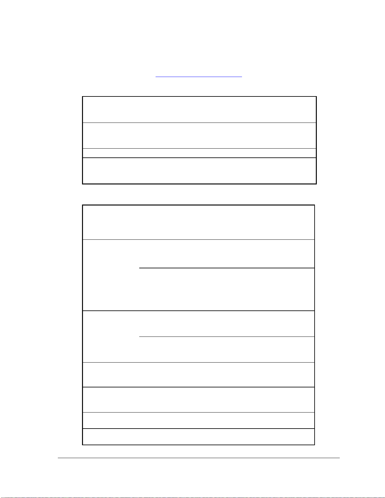
10 Specifications
I/O Terminations
6,8,9 and 10 pole, removable terminal blocks.
12 to 22 AWG
15A contacts
Dimensions
SCADAPack
8.40 inch (213mm) wide
6.13 inch (155mm) high
2.80 inch (72mm) deep
Packaging
corrosion resistant zinc plated steel with black enamel paint
Environment
5% RH to 95% RH, non-condensing
–40oC to 70oC
–40oF to 158oF
Communication
Ports, 5203
controller board
2 RS-232 serial ports (COM1, COM2)
Data Terminal Equipment (DTE)
DE-9P male connector
Communication
Ports, 5204
controller board
One RS-232 serial port (COM2)
Data Terminal Equipment (DTE)
DE-9P male connector
One RS-485 serial port (COM1)
2 wire half duplex
4 wire full or half duplex
optional termination resistors
Communication
Ports
5604 I/O
Modulue
one RS-232 serial port (COM3)
Data Terminal Equipment (DTE)
DE-9P male connector
5604 I/O
Module
one RS-232 serial port (COM3)
Data Terminal Equipment (DTE)
8 pin modular jack
Baud Rates
(COM1, COM2)
300, 600, 1200, 2400, 4800, 9600, 19200, 38400
default: 9600
Baud Rate
(COM3)
Where applicable
1200, 2400, 4800, 9600, 19200, 38400, 57600, 115200
Default: 9600
Parity
none, even, or odd
Default: none
Word Length
7 or 8 bits
Default: 8 bits
Disclaimer: Control Microsystems reserves the right to change product specifications without
notice. For more information visit www.controlmicrosystems.com .
10.1 General
10.2 Communications
5604 Input/Output (I/O) Module - Hardware Manual
October 19, 2007
Page 31
30
Stop Bits
1 or 2 bits
Default: 1 bit
Duplex (COM1,
COM2)
full or half with RTS/CTS control
Default: full
Duplex (COM3)
half with RTS/CTS control
Cable Length
RS-232 –maximum 50 ft (15.2 m)
RS-485 –maximum 4000 ft (1200 m)
Protocol 5203
and 5204
Controller
Boards
TeleBUS (compatible with Modbus RTU and Modbus ASCII)
DF1 and DNP Protocols optional
Default: Modbus RTU
Protocol Modes
5203 and 5204
Controller
Boards
slave, master, master/slave, store and forward
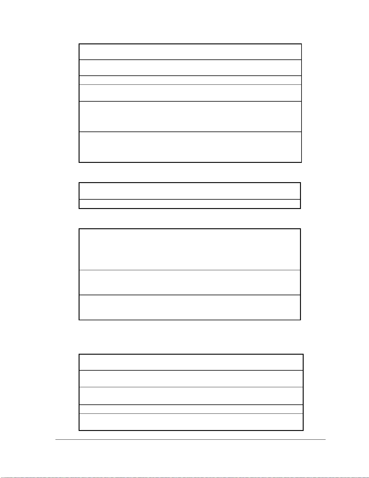
10.3 Visual Indicators
Digital I/O
(5604 I/O Module)
32 red LED’s
Push-button
LED power toggle
DC power Input
30V maximum
11V minimum
12V at 5mA during Sleep Mode
12V at 10mA with no loading on the boosted 24V Vloop
12V at 550mA with 88% efficiency 23V/0.25A loading
24Vdc Power
Output
22.5 to 25.2 Vdc with 0 to 0.25A load.
Shutdown current limiting typically 0.36A.
Efficiency 88-92%, 12V on DC PWR input
5V power
required
170mA with LED’s enabled and all I/O on
15mA with LED’s enabled and all I/O off
15mA with LED’s disabled
Input Points
8 at 10V/20mA: 250 resistance, user
configurable with jumper link
Resolution
15 bits over the 10V measurement range
14 bits over the 20mA measurement range
Input Resistance
20k for 10V inputs
250 for 20mA inputs
Converter type
16 bit successive approximation
Accuracy
±0.1% of full scale at 25oC (77ºF)
±0.2% over temperature range
10.4 Power Supply
10.5 Analog Inputs
10.5.1 Inputs 0-7
5604 Input/Output (I/O) Module - Hardware Manual
October 19, 2007
Page 32
31
Type
single ended
Calibration
Calibration constants stored in on board
microcontroller EEPROM.
Normal mode rejection
26 dB at 50/60 Hz Maximum filter setting
21 dB at 50/60 Hz Medium filter setting
14 dB at 50/60 Hz Minimum filter setting
5 dB at 50/60 Hz No filter
Over-scale Input Capacity
Measures up to 10V/40mA
Inputs clamped between 12 and 17V
Transient: 2.5kV surge withstand capability as
per ANSI/IEEE C37.90.1-1989
Isolation
Analog common side connected to Chassis
Ground
Response Time
For 90% signal change, 60/50Hz.
155/185ms Maximum filter setting
85/ 95ms Medium filter setting
45/ 55ms Minimum filter setting
30ms No filter
Input Points
1 at 0-32.768V
Resolution
10 bits over the 32.768V measurement range
Input Resistance
600k for 32.768V inputs
Converter type
10 bit successive approximation
Accuracy
±0.25% of full scale at 25oC (77ºF)
±1% over temperature range
Type
single ended
Calibration
Calibration constants stored in on board
microcontroller EEPROM
Over-scale Input Capacity
(without damage)
Transient: 2.5kV surge withstand capability as
per ANSI/IEEE C37.90.1-1989
Isolation
Analog common side connected to Chassis
Ground
Response Time
30ms for 90% signal change.
Output Points
2 (when optional 5305 analog output module installed)
Output Signal
Range
0-20mA
Maximum Load
Resistance
925 with 24Vdcinput voltage or when internal 24V power
supply is on.
375 with 12Vdc input voltage
250 with input voltage at power supply turnoff
Output Type
Single ended regulation on positive side with common
negative return
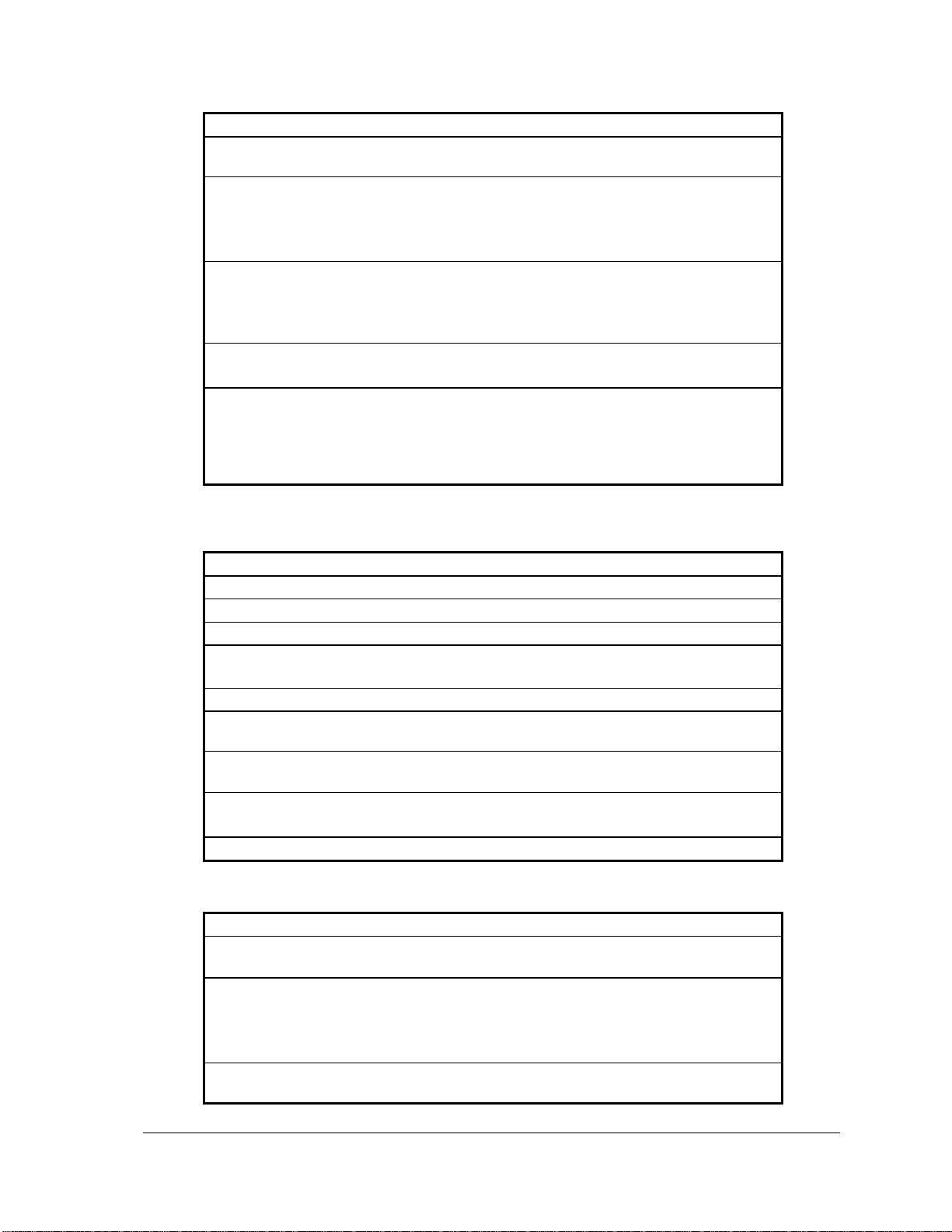
10.5.2 Input 8
10.6 Analog Outputs
5604 Input/Output (I/O) Module - Hardware Manual
October 19, 2007
Page 33
32
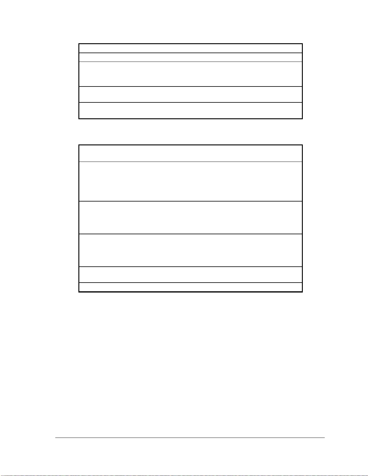
Isolation
Analog common side connected to Chassis Ground.
Resolution
12 bits
Accuracy
Specified from 0.5-20mA
±0.15% of full scale at 25oC (77oF)
±0.25% of full scale over temperature range
Noise and
Ripple
0.04% maximum
Transient
Protection
Transient: 2.5kV surge withstand capability as per ANSI/IEEE
C37.90.1-1989
I/O points
32 points in 4 group of 8.
Each point is an input and an output.
Output Rating
1.0Adc maximum
0.35V maximum drop at 1.0A
0.05V maximum drop at 0.1A
Open drain sinking when ON.
28V maximum when OFF.
Input Rating
Dry contact input.
Wetting current typically 5mA, pulsed.
Contact closure to ground is ON.
Open input is OFF.
Digital Input
Thresholds
0.9V typical turn on input voltage.
Less than 0.4V guaranteed turn on input voltage.
1.5V typical turn off input voltage.
Greater than 2.2V guaranteed turn off input voltage.
Transient
Protection
2.5kV surge withstand capability as per ANSI/IEEE
C37.90.1-1989
Isolation
Common ground return connected to Chassis Ground.
10.7 Digital Inputs
5604 Input/Output (I/O) Module - Hardware Manual
October 19, 2007
Page 34
33
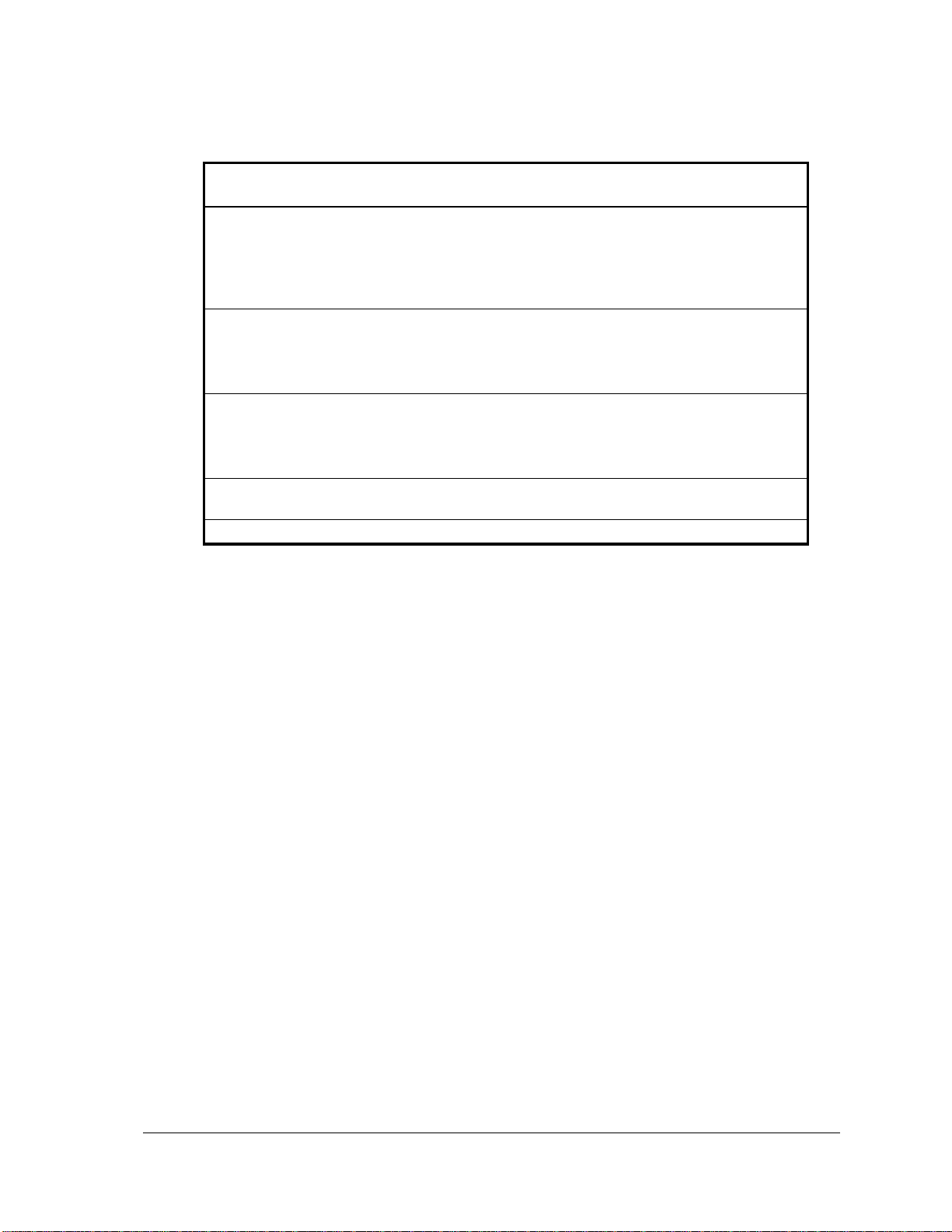
10.8 Digital Outputs
I/O points
32 points in 4 group of 8.
Each point is an input and an output.
Output Rating
1.0Adc maximum
0.35V maximum drop at 1.0A
0.05V maximum drop at 0.1A
Open drain sinking when ON.
28V maximum when OFF.
Input Rating
Dry contact input.
Wetting current typically 5mA, pulsed.
Contact closure to ground is ON.
Open input is OFF.
Digital Input
Thresholds
0.9V typical turn on input voltage.
Less than 0.4V guaranteed turn on input voltage.
1.5V typical turn off input voltage.
Greater than 2.2V guaranteed turn off input voltage.
Transient
Protection
2.5kV surge withstand capability as per ANSI/IEEE C37.90.11989
Isolation
Common ground return connected to Chassis Ground.
5604 Input/Output (I/O) Module - Hardware Manual
October 19, 2007
Page 35
34
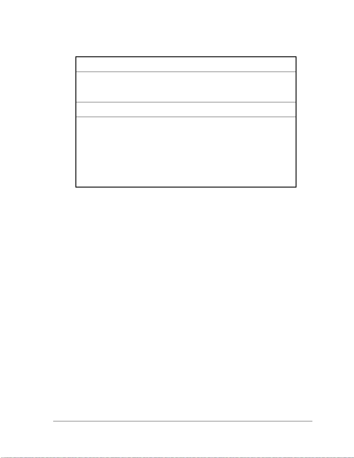
11 Approvals and Certifications
Safety
Non-Incendive Electrical Equipment for Use in Class I, Division
2 Groups A, B, C and D Hazardous Locations.
Digital
Emissions
FCC Part 15, Subpart B, Class A Verification
EN61000-6-4: 2001 Electromagnetic Compatibility Generic
Emission Standard Part2: Industrial Environment
C-Tick compliance. Registration number N15744.
Immunity
EN61000-6-2: 2001 Electromagnetic Compatibility Generic
Standards Immunity for Industrial Environments
Declaration
This product conforms to the above Emissions and Immunity
Standards and therefore conforms with the requirements of
Council Directive 89/336/EEC (as amended) relating to
electromagnetic compatibility.
P1 (5604) and P1B (5606 Models with digital inputs configured
below 30Vdc/60Vac are eligible to bear the CE mark. The Low
Voltage Directive is not applicable to these products in
applications below 30Vdc/60Vac.
The Low Voltage Directive is not applicable to the P1A (5604)
Model and is eligible to bear the CE mark.
5604 Input/Output (I/O) Module - Hardware Manual
October 19, 2007
 Loading...