

Page 1
MODEL 860
CAUTION:
• + Power Supply
• - Power Supply
• Signal IN
CONTROLLER
+IN •
COM •
+OUT •
•
+IN
•
COM •
+OUT •
• + Power Supply
• - Power Supply
• - Ctrl Negative
• Ctrl Ground
CONTROLLER
4 to 20 mA Output
TRANSDUCER
INSTALLATION
The Model 860 Pressure Transducer is a
compact instrument for measuring and
controlling the many different media that are
compatible with our sensing element. Positive,
negative, and differential pressures can be
measured in ranges from 0-0.25” WC to 0-15
PSI with 4 standard outputs: 1-5 VDC, 1-6
VDC, 1-10 VDC and 4-20mA. Split ranges and
custom outputs are also available.
INSTALLATION
1. Location- The model 860 pressure
transducer should be placed in as clean, dry and
vibration free a location as possible.
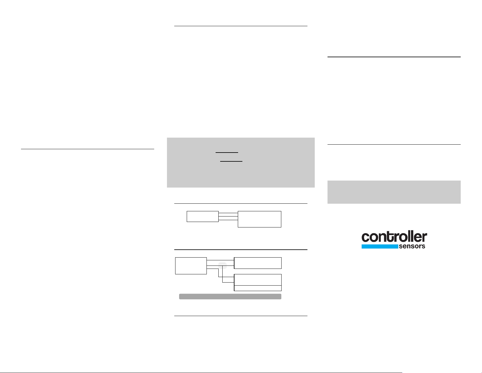
ELECTRICAL CONNECTIONS
All electrical connections to the 860 series
transducer are made to the pluggable screw
terminal block. The block is coded as follows.
1)+IN = Supply Positive, 2)COM = Common
Supply & Signal Negative 3)+OUT = Signal
Out(positive).
An external power supply delivering 12 - 24
VDC/24 VAC with a minimum of 10 mA (or
30mA for a 4-20mA output) is required to drive
the unit. If using a 1-10VDC output, or a 420mA output to drive a 500 ohm load, a
minimum of 18 VDC/24AC is required.
supply voltage. Do not apply voltage to
“+OUT” terminal as permanent damage
will occur.
Do not exceed specified
250 ohm resistor between the “+” and “-”
controller input terminals. This will safely
convert the 4-20mA signal to the desired
voltage.
OFFSET
The offset of the 860 series transducer is factory
set. If it should need adjustment upon arrival,
the offset pot is located next to the ports on the
end of the unit. With the transducer installed
and no pressure applied place a meter in series
with the supply negative (Ground), and the
signal out. Turn offset adjusting pot to desired
reading.
CUSTOMER SERVICE
If any problems are encountered during
installation please call the number below for
assistance.
2. Pressure Connections- The 860 pressure
transducer uses 2 barbed fittings for use with
1/8” ID vinyl or rubber tubing. Attach tubing
3 WIRE CONNECTION
from positive pressure or higher pressure source
to port marked High (P1) and lower or negative
pressure to opposite port (P2). Arrange tubing
to minimize stress on connections. If possible,
mount with ports facing down to aid in moisture
drainage.
3 WIRE TO 2 WIRE CONNECTION
Note: When removing tubing care should be
used to avoid breaking the ports. In some cases
the tubing should be cut off, rather than pulled
off, especially if stiff tubing is being used
3. Mounting- Attach the Model 860
Transducer to the mounting surface using 2
fasteners inserted through the two mounting
holes located on either the side mounting
flanges, or the holes at the top of the case. Do
not overtighten.
CONVERTING 4-20MA TO 1-5 VDC
860 Series Pressure transducers with a 4-20mA
current output can be easily adapted to
controllers requiring 1-5 VDC input. Insert a
Call 1-800-735-8998
7638 Washington Ave S
Eden Prairie, MN 55344
+1.800.735.8998 • +1.952.942.8743
FAX +1.952.942.8753
www.controllersensors.com
IN-860 Rev A
 Loading...