

Page 1
CAUTION:
• + Power Supply
• - Power Supply
• Signal IN
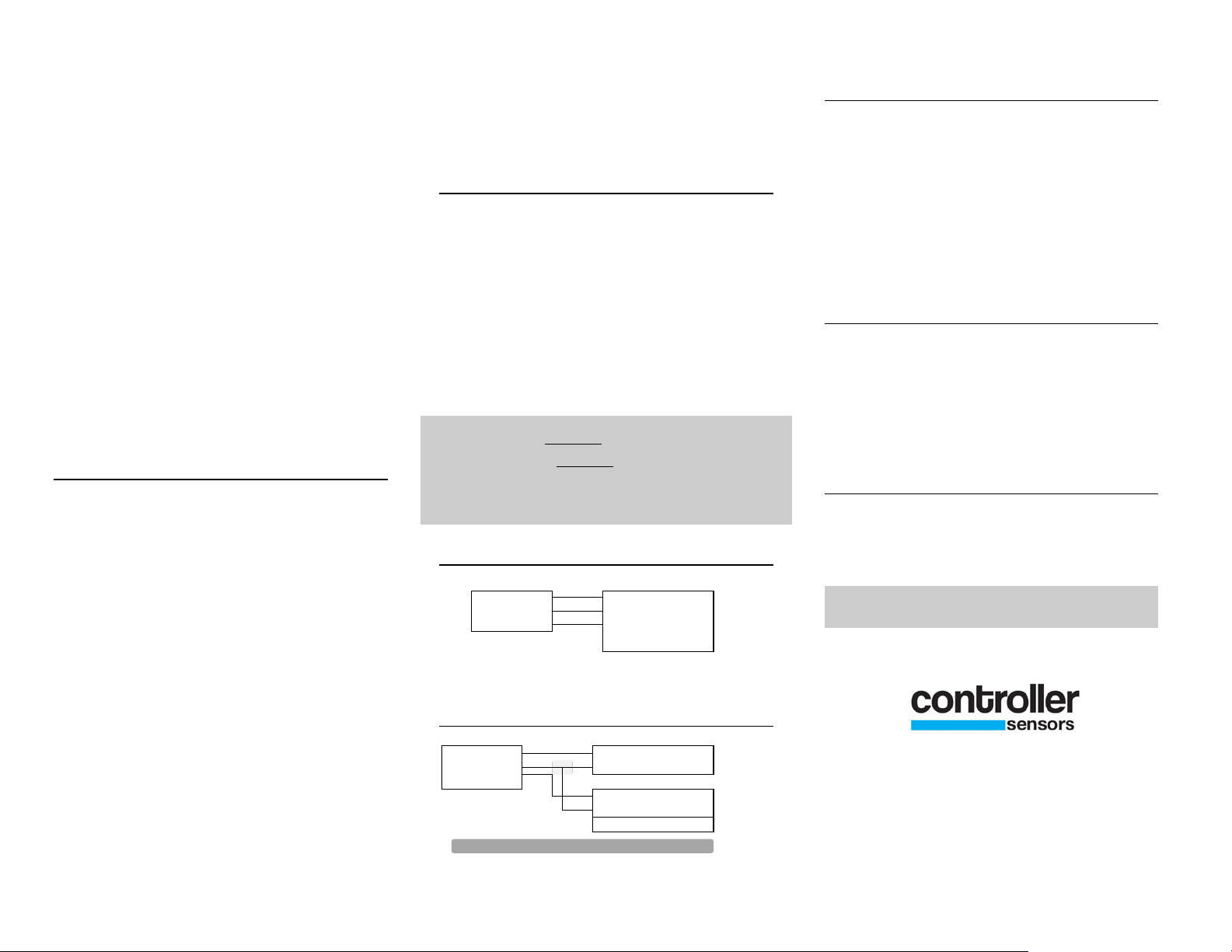
CONTROLLER
+IN •
COM •
+OUT •
•
+IN •
COM •
+OUT •
• + Power Supply
• - Power Supply
• - Ctrl Negative
• Ctrl Ground
CONTROLLER
4 to 20 mA Output
MODEL 851
TRANSDUCER
INSTALLATION
The Model 851 Pressure Transducer is a
compact instrument for measuring and
controlling the many different media that are
compatible with our sensing element. Each unit
is capable of measuring 4 full scale pressure
ranges and 3 or 4 split ranges. Each unit also
contains 3 output selections: 1-5 VDC, 1-10
VDC, and 4-20mA. Please see the spec sheet
for further information. All adjustments are
made outside the case and there are no jumpers
to lose!
INSTALLATION
1. Location- The model 851 pressure
transducer should be placed in as clean, dry and
vibration free a location as possible.
2. Pressure Connections- The 851 pressure
transducer uses 2 barbed fittings for use with
1/8” ID vinyl or rubber tubing. Attach tubing
from positive pressure or higher pressure
source to port marked High (P1) and lower or
negative pressure to opposite port (P2).
Arrange tubing to minimize stress on the
connections. If possible, mount with ports
facing down to aid in moisture drainage.
3. Mounting- Attach the Model 851
Transducer to the mounting surface using two
fasteners inserted through the two mounting
holes located on either the side mounting
flanges, or the holes at the top of the case. Do
not overtighten.
(When selecting between ranges you may
need to adjust the zero using the offset pot
located next to the range selector switch.)
ELECTRICAL CONNECTIONS
All electrical connections to the 851 series
transducer are made to the pluggable screw
terminal block. The block is coded as follows.
1) +IN = Supply Positive, 2) COM = Supply
Negative, 3) +OUT = Signal Out.
An external power supply delivering 18 - 24
VDC/24 VAC with min. 10 mA is required to
drive the unit (30mA is required for a 4-20mA
output).
OFFSET
The 851 series transducer is factory zeroed. If it
should need adjustment upon arrival the offset
pot is located next to the range selector switch
on the side of the unit. With the transducer
installed and no pressure applied place a meter
in series with the supply negative (Ground), and
the signal out. Turn offset adjusting pot to
desired reading.
SWITCH SETTINGS
Ranges are set using the rotary switch on the
side of the device. Choose the setting number
that matches the desired range shown on the
label. (Note: the offset may need to be
readjusted.) Output types are selected using the
Do not exceed specified
slide switch next to the terminal block.
supply voltage. Do not apply voltage to
“+OUT” terminal as permanent damage
will occur.
3 WIRE CONNECTION
CUSTOMER SERVICE
If any problems are encountered during
installation please call the number below for
assistance.
Call 1-800-735-8998
3 WIRE TO 2 WIRE CONNECTION
7638 Washington Ave S
Eden Prairie, MN 55344
+1.800.735.8998 • +1.952.942.8743
FAX +1.952.942.8753
www.controllersensors.com
IN-851 Rev A
 Loading...