

Page 1
MODEL750
CAUTION:
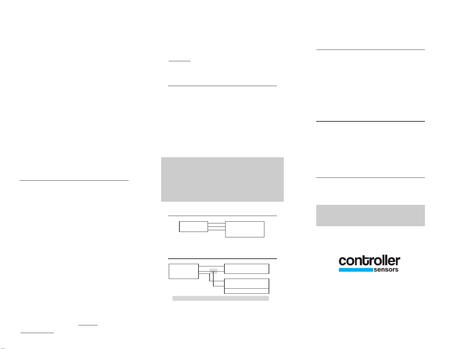
• + Power Supply
• - Power Supply
• Signal IN
CONTROLLER
IN + •red
IN - •blk
OUT •grn
•
IN + •red
IN - •blk
OUT •grn
• + Power Supply
• - Power Supply
• Signal
• Ctrl Ground
CONTROLLER
4 to 20 mA Output
TRANSDUCER
INSTALLATION
The Model 750 Pressure Transducer is a
competitively priced, extremely accurate,
auto-zeroing, transducer. The auto-zero
feature occurs approximately every 45
seconds and takes 400 milliseconds to
complete. The patented auto-zeroing
circuit has two main advantages, it
eliminates the need to adjust the zero
point after initial installation, and reduces
long term drift. Pressure ranges available
are 0-0.1” to 0-5” W.C., in four outputs 420mA, 1-5VDC, 1-6VDC and 1-10VDC.
INSTALLATION
1. Location- The model 750 pressure
transducer should be placed in as clean,
dry and vibration free a location as
possible.
2. Pressure Connections- The model
750 pressure transducer uses 2 brass
barbed fittings for use with 1/8”or 1/4”
ID vinyl or rubber tubing. Attach tubing
from positive pressure or higher pressure
source to port marked High (P1) and
lower or negative pressure to Low (P2)
port. Arrange tubing to minimize stress on
connections. If possible mount with ports
facing down, to aid in moisture drainage.
3. Mounting- Attach the Model 750
Transducer to the mounting surface using
2 fasteners inserted through the two
mounting holes located on the front edge
of the transducer case. Do not
overtighten. The offset of the 750 series
transducer is set at the factory, but may
need to be adjusted after installation.
NOTE: Allow 5 minutes to warm up
before adjusting the offset.
ELECTRICAL CONNECTIONS
All electrical connections to the 750 series
transducers are made to the 3 wire pigtail.
The 3 wire pigtail is coded as follows. Red
= + Supply, Black = - Supply, Green =
CONVERTING 4-20MA TO 1-5VDC
750 Series Pressure transducers with a 420mA output can be easily adapted to
receivers requiring 1-5 VDC input. Insert
a 250 ohm resistor between the + and –
controller signal input terminals. This will
safely convert the 4 to 20 mA signal to the
desired voltage.
OFFSET
Signal Out. An external power supply
delivering 24 VDC/24 VAC with min
70mA no load, and 100mA peak is
required to drive the unit.
Remove plug located on the front of the
transducer. With the transducer installed
and no pressure applied, place a meter
between the supply negative and the
output. Turn offset pot to desired reading.
Do not exceed specified
supply voltage. Do not apply voltage
to GREEN wire as permanent
damage will occur.
CUSTOMER SERVICE
If any problems are encountered during
installation please call the number below
for assistance.
3 WIRE CONNECTION
Call 1-800-735-8998
IN-750 Rev A
3 WIRE TO 2 WIRE CONNECTION
7638 Washington Ave S
Eden Prairie, MN 55344
+1.800.735.8998 • +1.952.942.8743
FAX +1.952.942.8753
www.controllersensors.com
 Loading...