

Page 1
MODEL 560
CAUTION :
• + Power Supply
• - Power Supply
• Signal IN
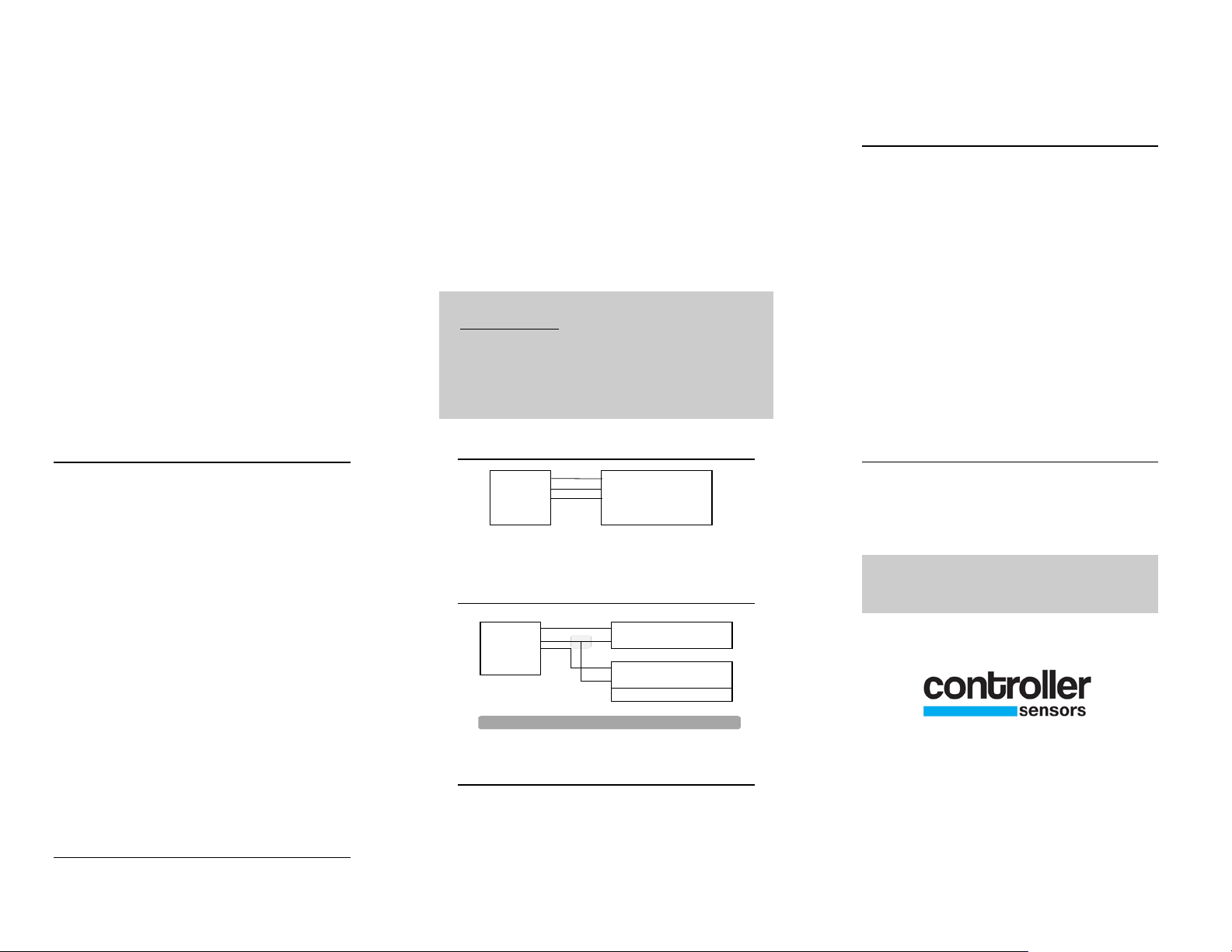
CONTROLLER
IN + •
IN - •
OUT •
GND •
•
IN + •
IN - •
OUT •
GND •
• + Power Supply
• - Power Supply
• Signal
• Ctrl Ground
CONTROLLER
4 to 20 mA Output
TRANSDUCER
INSTALLATION
The Model 560 Pressure Transducer is
available in both Differential and Gauge
configuration, in ranges from 0-2 to 0-500
PSI. This Transducer features a NEMA 4
enclosure and series 300 stainless steel
wetted parts making it compatible with
most wet and dry media. Pressures are
converted to three standard outputs, 0-5
VDC, 0-10 VDC and 4-20 mA with an
accuracy of +/- 0.5% F.S.O..
wire terminal strip. An external power
supply delivering 24 VAC/24 VDC, with
a minimum of 35 mA is required to drive
the unit.
The four wire terminal strip supplied with
the 560 series Transducer is labeled as
follows, +IN (Supply Positive), -IN
(Supply Negative), OUT (Signal Out),
GND (Common to Supply Negative).
Do not exceed specified
supply voltage. Do not apply voltage
to OUT terminal, as permanent
damage will occur.
convert the 4 to 20 mA signal to the
desired voltage.
OFFSET AND SPAN
Two adjustments are offered with the 560
series pressure transducer, offset and span.
After initial installation, the offset and
span can be adjusted by removing the top
cover and adjusting the labeled pots
located on the edge of the PCB. With the
transducer installed and no pressure
applied, place a meter between the supply
negative and the output terminal to set the
zero. Apply full-scale pressure and adjust
the span to the required voltage or current
reading. Repeat process until desired
reading is attained.
INSTALLATION
1. Location- the model 560 Pressure
Transducer should be placed in as dry and
vibration free a location as possible. If
possible, mount with connectors facing
down to aid in moisture drainage.
2. Pressure Connections- the 560 Series
Transducer uses 2 (Differential) or 1
(Gauge) 1/8” NPT female fittings. Always
use a wrench to hold the transducer
fittings while tightening the mating
connection.
3. Mounting- Attach the Model 560
Transducer using 4, 1/8” fasteners. The
mounting holes are located on the Four
Corners of the box, below the top cover.
ELECTRICAL CONNECTIONS
All electrical connections to the 560 series
Transducer are made to the internal four
3 WIRE CONNECTION
3 WIRE TO 2 WIRE CONNECTION
CONVERTING 4-20MA TO 1-5VDC
560 Series Pressure Transducers with a 420mA output can be easily adapted to
receivers requiring 1-5 VDC input. Insert
a 250 ohm resistor between the + and controller input terminals. This will safely
CUSTOMER SERVICE
If any problems are encountered during
installation please call the number below
for assistance
Call 1-800-735-8998
7638 Washington Ave S
Eden Prairie, MN 55344
+1.800.735.8998 • +1.952.942.8743
FAX +1.952.942.8753
www.controllersensors.com
IN-560 Rev A
 Loading...