

Page 1

ELPRO INNOTEK S.p.A.
Transmitter
Solutions
Thank you for choosing a Transmitter Solutions product .
Please read this manual carefully before using the p roduct.
Made in Italy. Copyright
1 - TRANSMITTER OVERVIEW
1A - General information
1B - Technical specifications
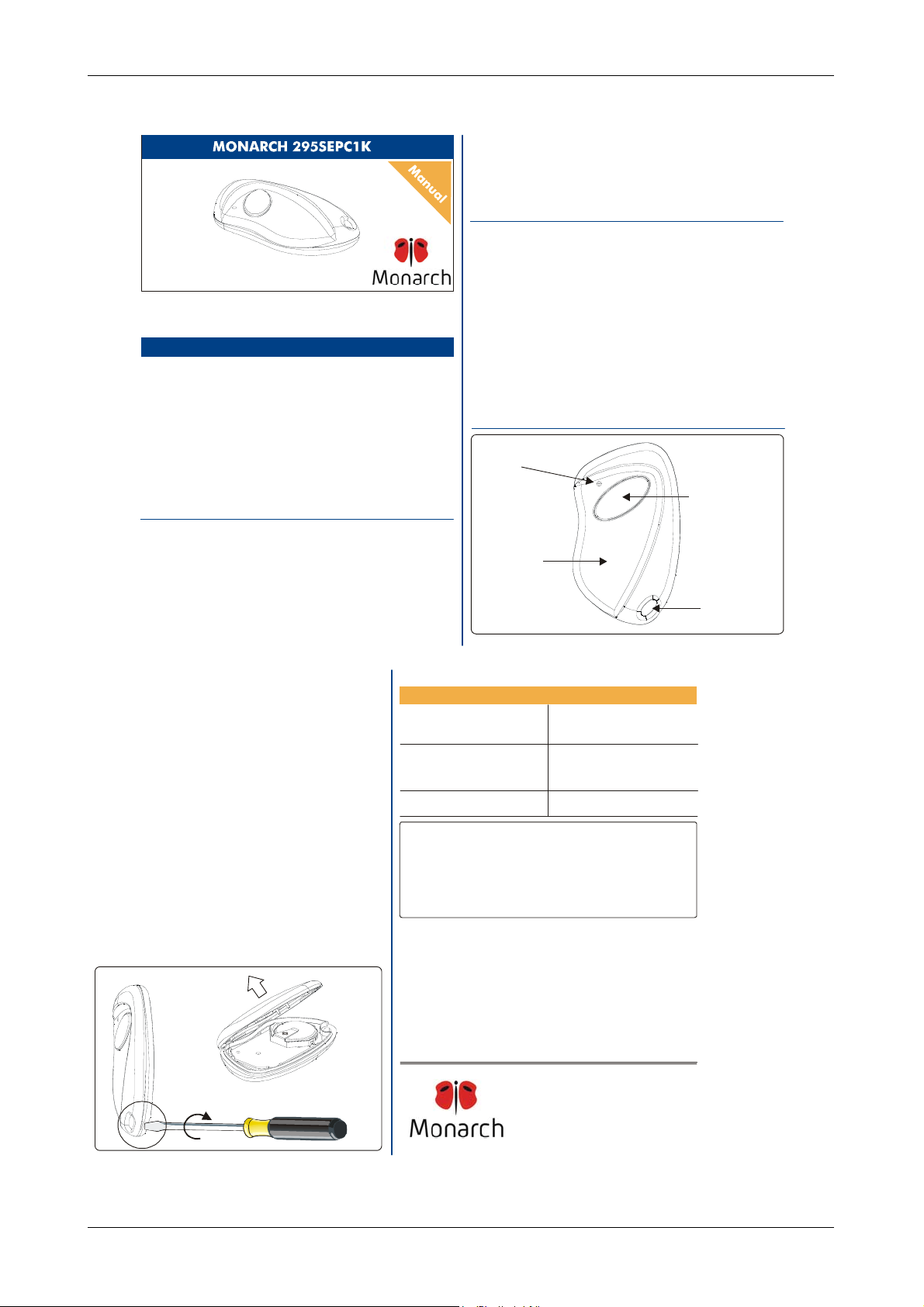
1C - Main components
2 - NUMBERING
3 - PROGRAMMING
4 - OPERATION
5 - BATTERY ACCESS
6 - TROUBLESHOOTING
MONARCH ONE BUTTON - Type: 295SEPA1K
Annex 8 : User manual
The - 295R receiver which operates with this
Transmitter Solutions
transmitter has a Wiegand 33 bit and can operate any type of access
control system equipped with the same protocol. The CR 2016 lithium
© 2006 by Transmitter Solutions
CONTENTS
batteries of the transmitter have a shelf life of about 6 months.
product fully complies with the
European Directives 99/5/CE, 89/336/CEE, 73/23/CEE.
1B - Technical specifications
Operating frequency 295 MHz
Number of keys: 1
Battery : 2 x 3V lithium batteries CR2016
Battery life: 18 24 months
Number combinations : 16,777,216
Protocol : AUTOkey compatible
Operating temperature: -20°F÷+131°F (-20°C÷+55°C)
Overall dimensions: 2.4”x1.4”x0.51” (61x36x13 mm)
Weight: 0.49 oz. (14 gr.)
1C - Main compon ents
Red
LED
Part 15 of FCC Regulations and
÷
Light grey
push-button
TCF-105
The
1A - General information
The Transmitter Solutions - Monarch 295SEPA1K transmitter is a key
chain style mini transmitter operating at 295 MHz. It has been designed
for use w ith programmable tel ephone entry, security, and access contro l
systems opera ting with a 295 MHz frequency re ceiver.
The protocol is AUTOkey compatible and the code sent by the
transmitter includes a 24 bit security code which allows up to
16,777,216 code combinations.
2 - NUMBERING
Each transm itter is man ufactured and sold with a d ifferent factory-set serial
number .
3 - PROGRAMMING
The transm itter must be programm ed into yo ur system m emory.
Your own installer or reseller will provide you the nec essary instructions for you r
system.
4 - OPERATION
A - Firmly depress the button until the small red LED illuminates.
B - After th e LED has illuminated, releas e the button.
If the device you are attempting to activa te does not respond, repe at steps A and B
or consult section 6 ( Troubleshooting ) of this manual.
5 - BATTERY ACCESS
To acc ess the batte ry open the ca se with a screwdriv er acting on th e slot betwe en
the cover and th e botto m and remove the botto m, as sh own in fig. 3a an d 3b.
Slide out the old batteries and replace them with the new ones ]
respecting the polari ty, with the positive (+) si de upward.
NOTE: Please dispose of the batteries properly according to local laws and
regulations.
Test proper batter y installation by verifying that the red LED illuminates when
the button is pushed.
Fig. 3a
[CR2016
Dark grey
case
Fig. 2
6 - TROUBLESHOOTING
PROBLEM
The system does not recei ver the
transmitter signal.
The transmitter LED will not light
The system does not receiver the
transmitter signal.
The transmitter LED is ON
The operating range is reduced
Transmitter Solutions - Type : 295SEPA1K
This d evice compli es with FCC Rules
Operation is subject to the following two conditions:
(1) This device may not cause harmful interference, and
(2) this device must accept interference received, includin g
interference that may caus e undesired operation.
Any changes or modi fication to Transmitter Solutions eq uipment not expressly
approved by could void the manufacturer’s warranty.Transmitter Soluti ons
The warranty period of 295 transmitters is 24 months,
beginning from the manufactur ing date of the transmitter. During this period , if the
product does operate correctly, due to a defective component, the product will be
repair ed or replace d at the s ole discre tion of .
The warranty does not extend to the tra nsmitter case which can b e damaged by
conditions outside the control of or to battery life.
FCC ID : SU7295SEPA1K
Notice
WARRANTY
Transmit ter S olut ions
Tra ns mi tt er S ol ut io ns
SOLUTION
Replace the transmitter
batteri es
Check to verify the
transmitter is programmed
into your system
Replace the transmitter
batteri es
Part . 1 5 of the
Tra ns mi tt er S ol ut io ns
Key
holder
ring
Fig. 3b
TRANSMITTER SOLUTIONS
2505 Chandler Avenue , Suite, 1
Las Vegas, NV 89120 -
(866) 975- 0101 - (866) 975-0404 Fax
sales@transmittersolutions.com
IS-TM12ACCUK Rev. 1 del 12.05.2006
Annex 8 = User manual Pag 1 of 2
Page 2
ELPRO INNOTEK S.p.A.
Transmitter
Solutions
Thank you for choosing a Transmitter Solutions product .
Please read this manual carefully before using the p roduct.
Made in Italy. Copyright
1 - TRANSMITTER OVERVIEW
1A - General information
1B - Technical specifications
1C - Main components
2 - NUMBERING
3 - PROGRAMMING
4 - OPERATION
5 - BATTERY ACCESS
6 - TROUBLESHOOTING
© 2006 by
Transmitter Solutions
CONTENTS
Type: 295SEPC1K
The - 295R receiver which operates with this
Transmitter Solutions
transmitter has a Wiegand 26 bit and can operate any type of access
control system equipped with the same protocol. The CR 2016 lithium
batteries of the transmitter have a shelf life of about 6 months.
product fully complies with the
European Directives 99/5/CE, 89/336/CEE, 73/23/CEE.
1B - Technical specifications
Operating frequency 295 MHz
Number of keys: 1
Battery : 2 x 3V lithium batteries CR2016
Battery life: 18 24 months
Number combinations : 65,536
Protocol : ClikCard® compatible
Different Facilities codes 64
Operating temperature: -20°F÷+131°F (-20°C÷+55°C)
Overall dimensions: 2.4”x1.4”x0.51” (61x36x13 mm)
Weight: 0.49 oz. (14 gr.)
1C - Main compon ents
Red
LED
Part 15 of FCC Regulations and
÷
Dark grey
push-button
TCF-105
The
1A - General information
The - Monarch 295SEPC1K transmitter is a key
Transmitter Solutions
chain style mini transmitter operating at 295 MHz. It has been designed
for use w ith programmable tel ephone entry, security, and access contro l
systems opera ting with a 295 MHz frequency re ceiver.
The protocol is ClikCard® compatible and the code sent by the
transmitter includes a 16 bit security code which allows up to 65,536
combinations and 6 bit of facility code for 64 different combinations.
2 - NUMBERING
Each transm itter is man ufactured and sold with a d ifferent factory-set serial
number .
3 - PROGRAMMING
The transm itter must be programm ed into yo ur system m emory.
Your own installer or reseller will provide you the nec essary instructions for you r
system.
4 - OPERATION
A - Firmly depress the button until the small red LED illuminates.
B - After th e LED has illuminated, releas e the button.
If the device you are attempting to activa te does not respond, repe at steps A and B
or consult section 6 ( Troubleshooting ) of this manual.
5 - BATTERY ACCESS
To acc ess the batte ry open the ca se with a screwdriv er acting on th e slot betwe en
the cover and th e botto m and remove the botto m, as sh own in fig. 3a an d 3b.
Slide out the old batteries and replace them with the new ones ]
respecting the polari ty, with the positive (+) si de upward.
NOTE: Please dispose of the batteries properly according to local laws and
regulations.
Test proper batter y installation by verifying that the red LED illuminates when
the button is pushed.
[CR2016
Fig. 3a
Dark grey
case
Fig. 2
6 - TROUBLESHOOTING
PROBLEM
The system does not recei ver the
transmitter signal.
The transmitter LED will not light
The system does not receiver the
transmitter signal.
The transmitter LED is ON
The operating range is reduced
Transmitter Solutions - Type : 295SEPC1K
FCC ID : SU7295SEPC1K
This d evice compli es with FCC Rules
Operation is subject to the following two conditions:
(1) This device may not cause harmful interference, and
(2) this device must accept interference received, includin g
interference that may caus e undesired operation.
Any changes or modification to equipment not expressly
approved by could void the manufacturer’s warranty.
Transmitter Soluti ons
Notice
Transmitter Solutions
WARRANTY
The warranty period of 295 transmitters is 24 months,
beginning from the manufactur ing date of the transmitter. During this period , if the
product does operate correctly, due to a defective component, the product will be
repair ed or replace d at the s ole discre tion of .
The warranty does not extend to the tra nsmitter case which can b e damaged by
conditions outside the control of or to battery life.
Transmit ter S olut ions
Tra ns mi tt er S ol ut io ns
SOLUTION
Replace the transmitter
batteri es
Check to verify the
transmitter is programmed
into your system
Replace the transmitter
batteri es
Part . 1 5 of the
Tra ns mi tt er S ol ut io ns
Key
holder
ring
Fig. 3b
TRANSMITTER SOLUTIONS
2505 C handler Av enue, Suite, 1
Las Vegas, NV 89120 -
(866) 9 75-0101 - (866) 97 5-0404 Fax
sales@transmittersolutions.com
IS-TM12CCCUK Rev. 0 del 22.03.2006
Annex 8 = User manual Pag 2 of 2
 Loading...