

Page 1
iDProx
Thank you for purchasing the iDProx proximity card
reader! Check out our online guide at:
www.controlid.com.br/userguide/idprox-en.pdf
Necessary Materials
In order to install your iDProx, you will need the
following items: drill, wall plugs and screws,
screwdriver, 12V power supply capable of supplying
at least 1A and an electronic lock.
Installation
For the correct operation of your iDProx, the
following precautions should be taken:
• Install in a place that is not exposed to direct
sunlight and that is protected from rain and other
natural phenomena
• Install iDProx 1,5m above the floor.
• Before securing the equipment in place, ensure all
connecting cables are correctly routed towards the
equipment.
The equipment installation process is simple and
should follow the sequence below:
1. Remove the plastic lens from the iDProx
with a screwdriver that is at least 3 mm wide
(to avoid damaging the plastic):
2. Use the reference pattern on the back of
this guide to drill the 2 holes
3. Insert the wall plugs completely into the
holes made
4. Route all of the cables required for the
operation and connect them to the iDProx
cables
5. Secure the iDProx using two screws
6. Place the plastic lens positioning it
properly and securing the top first and then
the bottom
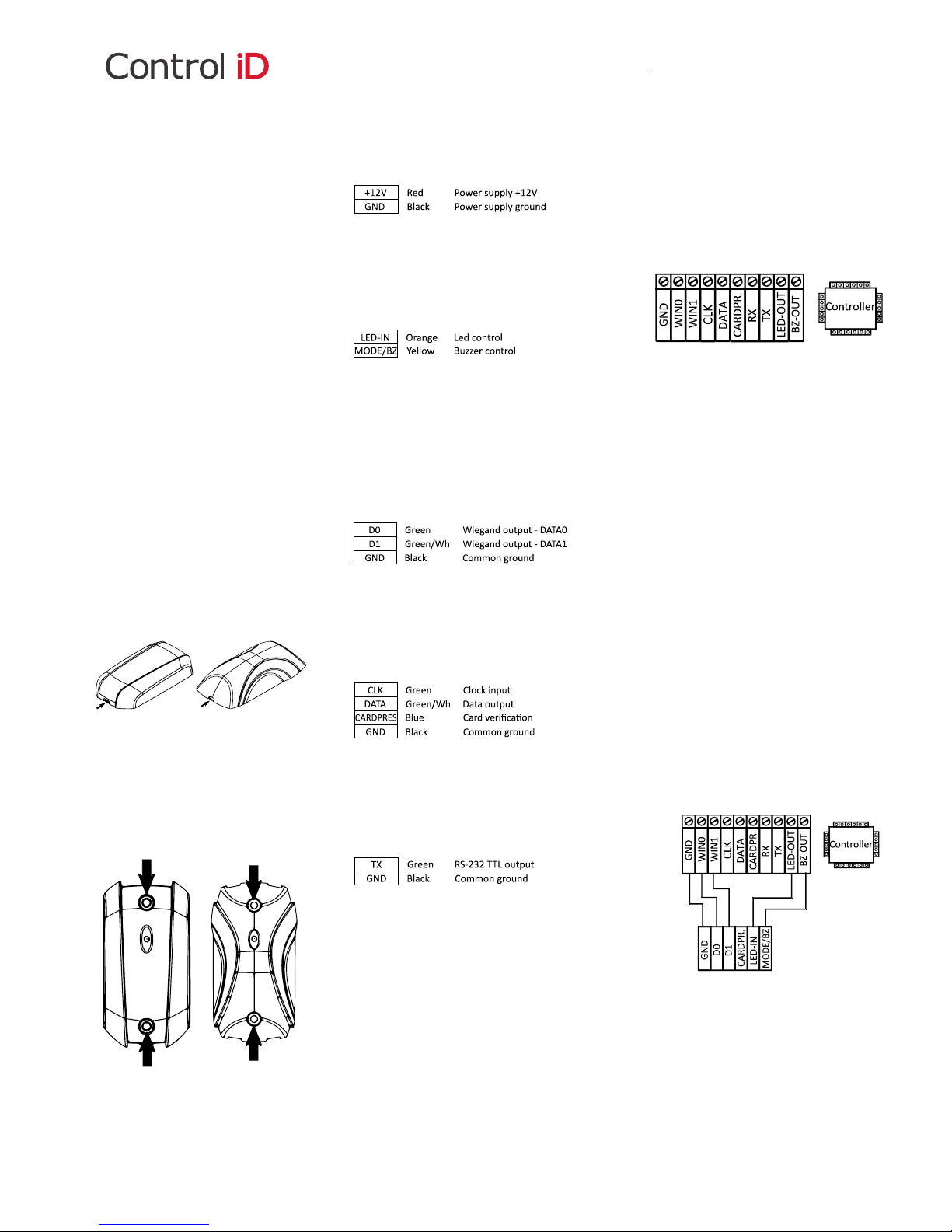
Connection Pins
⚠ Warning: The Green, Green with White and Blue
wires depend on the operating mode that is set up
on the equipment (Wiegand or ABA Track II).
Power Supply
⚠ Connection to a +12V power supply capable of
supplying at least 1A is fundamental for the correct
operation of the equipment
Led Control and Buzzer
By connecting the LED-IN pin to ground, the internal
LED turns red.
By connecting the MODE / BZ pin to the ground, the
buzzer is activated.
The MODE / BZ pin is also used for configuring the
operating mode (Wiegand or ABA Track II)
Wiegand Output
⚠ Warning: The Green, Green with White and Blue
wires depend on the operating mode that is set up
on the equipment (Wiegand or ABA Track II).
Output ABA Track II
⚠ Warning: The Green, Green with White and Blue
wires depend on the operating mode that is set up
on the equipment (Wiegand or ABA Track II).
RS232 Output
Operating Mode Selection
The reader's operating mode can be selected as
Wiegand or ABA Track II. To do this, you must
perform a simple procedure:
1. Turn the iDProx off
2. Connect the MODE / BZ (Yellow) cable to D0,
D1 or CARDPRES according to the table.
3. Turn the iDProx on. The buzzer will sound
and the LED will light up according to the
selected configuration.
4. Turn the iDProx off and reconnect all cables
normally: D0, D1, MODE / BUZZER etc.
5. Turn the iDProx on. The device will work
according to the mode previously selected.
Connection
Mode
LED
MODE/BZ + D0
Wiegand 26
Green
MODE/BZ + D1
Wiegand 34
Yellow
MODE/BZ + CARDPRES
ABA
Red
Communication Protocols
In order for the iDProx to work properly, it must be
connected to a controller that can communicate
with the reader in one of the three supported
protocols.
This controller will be represented in this guide as
depicted below:
The WIN1 and WIN0 inputs are used for the
Wiegand protocol; CARDP, CLK and DATA inputs
are used for ABA Track II and the RX and TX inputs
are used for communication via RS232.
⚠ The names of the inputs may vary according to
the controller.
⚠ The controller inputs depend on the model and
brand.
Wiegand
The Wiegand protocol uses 3 wires: DATA0, DATA1
and GND. When there is no data to be received,
both DATA0 and DATA1 remain in logical level 1, ie.
it is possible to measure 5V between the cables and
GND. When a 0 bit is received, DATA0 will go to
logical level 0 (which means that you can measure
0V between this cable and GND) and DATA1 will
remain at logical level 1. When a bit 1 is received,
DATA1 will go to logical level 0 and DATA0 will
remain at logic level 1.
The necessary connections to use this protocol are
presented below:
Page 2
ABA Track II
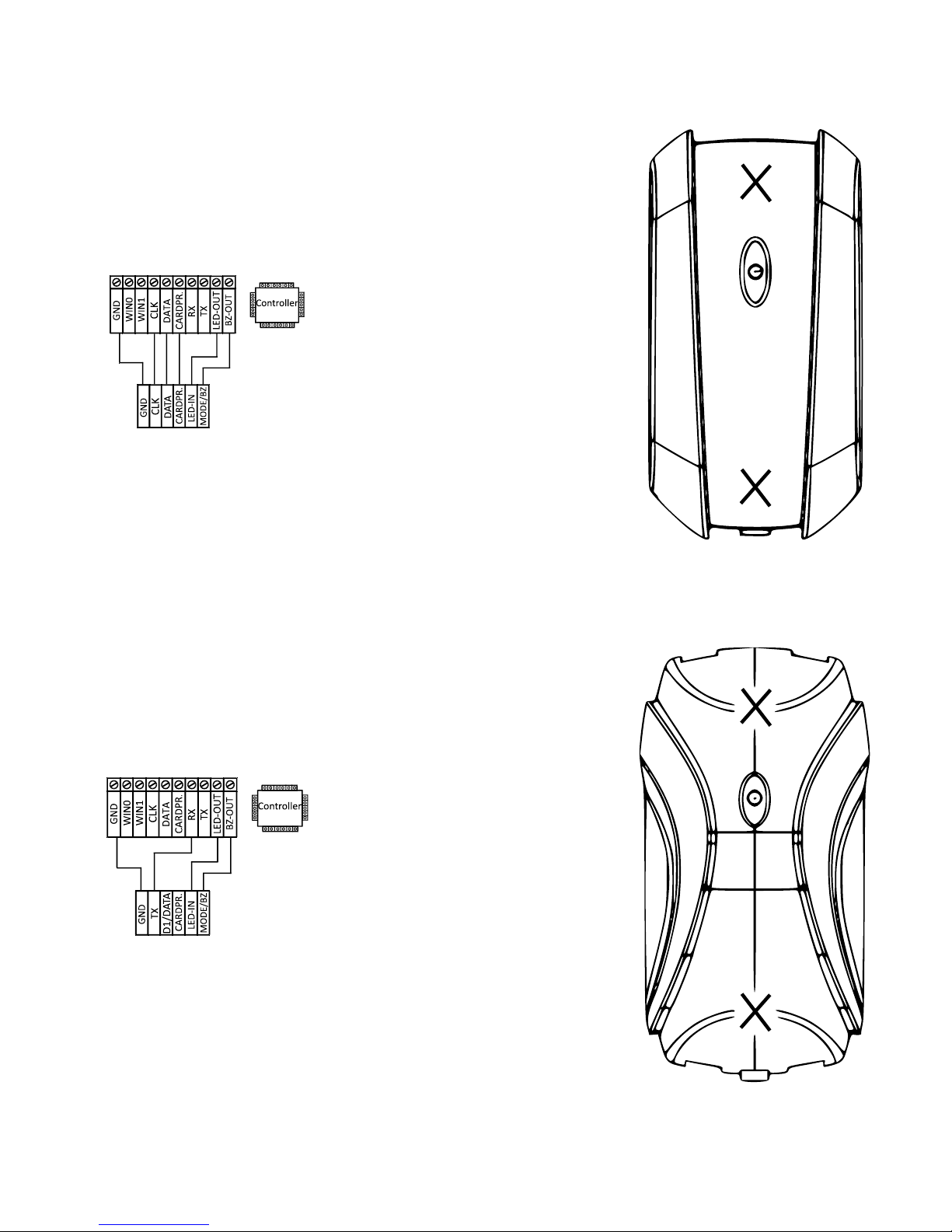
The ABA Track II protocol uses 4 wires: CARDPRES,
CLK, DATA and GND. The CARDPRES output remains
at the logical level 1 while there is no card to be
read. When a card is close to the reader, the
CARDPRES output goes to logical level 0 and the
data is read from DATA each time the CLK input
goes from the logical level 1 to logical level 0. When
all the data is sent, the CARDPRES output goes back
to the logical level 1 and data is not read anymore.
The wiring diagram for this case is presented below:
⚠ Warning! The Wiegand protocol is faster and
the most efficient option
⚠ You cannot use this protocol with the iDBox
controller.
RS-232
The RS232 protocol usually uses 3 cables: RX, TX
and GND.
Data is transmitted by the TX output and received
by the RX input. No synchronization signal is
required in this case.
The output of this protocol, through this reader, is
TTL, i.e. a logical level 1 is represented by 5V and
logical level 0 is represented by 0V, with no negative
voltage.
The wiring diagram is presented below:
Technical Specifications
Power Supply
External power supply 12VDC /1A (not included).
1.2W nominal consumption.
Identification
Proximity card: ASK, FSK, PSK or Mifare.
⚠ The type of card must be defined before
purchasing.
Range
ASK: 15cm | FSK: 10cm | PSK: 10cm | Mifare: 6cm
Communication
Wiegand output, may be configured for ABA Track
II.
RS232 TTL shared output
Interface
Yellow, green and red LED controlled by an input.
4kHz and 70dbA Buzzer @100mm controlled by an
input.
Dimensions and weight
Slim Model
20mm x 95mm x 51mm (H x W x L)
103g
Compact Model
22mm x 130mm x 55mm (H x W x L)
102g
Assembly Instructions
iDProx Compact
iDProx Slim
Manual – iDProx – Versão 2.4 EN – Control iD 2017©
 Loading...