

Page 1
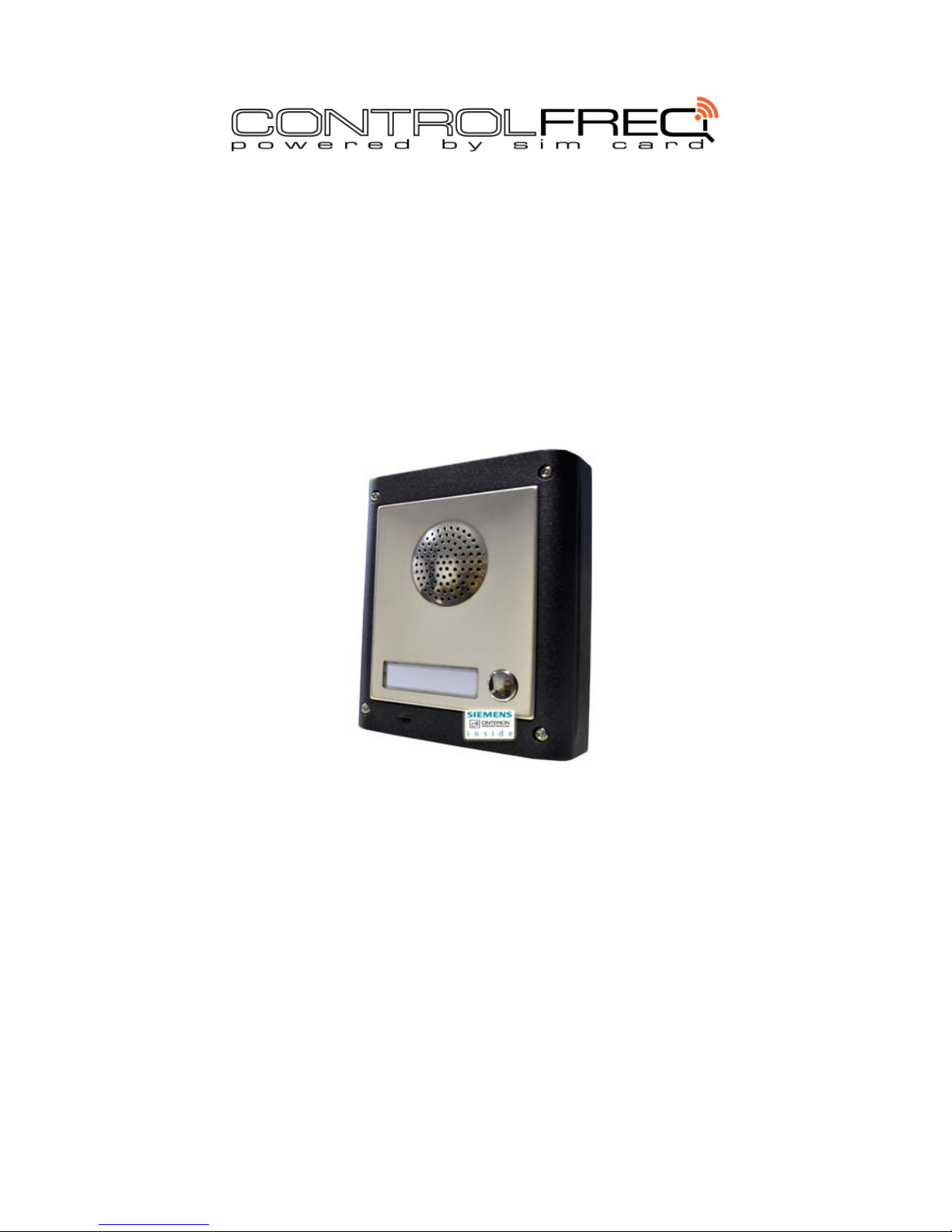
QUICK-FIT
COMPACT GSM INTERCOM SYSTEM
INSTALLATION MANUAL
Version: QUICK-FIT GSM-Installation-Manual_v1.6
Page 2

QUICK‐FITGSM
INSTALLATIONMANUAL
Page2
Contents
1 FOR YOUR SAFETY................................................................................................................................................5
2 INTRODUCTION ......................................................................................................................................................6
3 FEATURES AND APPLICATIONS...........................................................................................................................7
4 START UP ................................................................................................................................................................8
5 LED DISPLAY........................................................................................................................................................... 9
6 CLEAR ALL PROGRAMMED DATA FROM SIM ...................................................................................................10
7 CONNECTION DIAGRAM ......................................................................................................................................11
8 PROGRAMMING QUICK-FIT GSM........................................................................................................................12
9 THE QUICK-FIT GSM PARAMETERS...................................................................................................................13
9.1 ALARM SUPPORT...............................................................................................................................................................13
9.2 OUTPUT MANAGEMENT ...................................................................................................................................................17
9.3 SECURITY LEVEL - SL........................................................................................................................................................18
9.4 SET-UP PARAMETERS.......................................................................................................................................................21
9.5 SMS MESSAGES EDITOR....................................................................................................................................................24
9.6 INTERCOM............................................................................................................................... ..........................................25
9.7 CLIP....................................................................................................................................................................................28
9.8 EVENT LOGGING..............................................................................................................................................................30
9.9 SPECIAL SMS COMMANDS......................................................................................................................................................31
10 PRINT-OUT OF THE PARAMETERS....................................................................................................................33
10.1 RECEIVE ALL PARAMETERS (PALL)..................................................................................................................................33
10.2 CHECK SW REVISION (PSW).....................................................................................................................................................33
10.3 CHECK SIGNAL QUALITY (PSQ)..................................................................................................................................................33
10.4 RECEIVE TELEPHONE NUMBERS (PTN)...........................................................................................................................33
10.5 RECEIVE LINKS (PLN)........................................................................................................................................................33
10.6 RECEIVE INPUT PARAMETERS (PIN)................................................................................................................................33
10.7 RECEIVE INPUT FILTER VALUE (PID)...............................................................................................................................34
10.1 RECEIVE INPUT FILTER VALUE (POD).............................................................................................................................34
10.2 RECEIVE DELAY BEFORE DIAL VALUE (PDD)...................................................................................................................34
10.3 RECEIVE ACCESS TELEPHONE NUMBERS (PSL)..............................................................................................................34
10.4 RECEIVE OUTPUT PARAMETERS (POS)...........................................................................................................................34
10.5 RECEIVE ALL PROGRAMMED SMS MESSAGES (P#)..........................................................................................................34
10.6 RECEIVE SET UP PARAMETERS VALUE (PPA)..................................................................................................................34
10.7 RECEIVE CREDIT PARS PARAMETERS (PCREF).............................................................................................................................35
10.8 RECEIVE ALL CLIP PARAMETERS (PCLP)..........................................................................................................................35
10.9 RECEIVE INTERCOM BUTTON 1 PARAMATERS (PDEA)...................................................................................................................35
10.10 RECEIVE INTERCOM BUTTON 2 PARAMATERS (PDEB)..............................................................................................................35
10.11 RECEIVE INTERCOM BUTTON 3 PARAMATERS (PDEC)..............................................................................................................35
10.12 RECEIVE INTERCOM BUTTON 4 PARAMATERS (PDED)..............................................................................................................36
10.13 RECEIVE INTERCOM BUTTON 5 PARAMATERS (PDEE)..............................................................................................................36
10.14 RECEIVE INTERCOM BUTTON 6 PARAMATERS (PDEF)..............................................................................................................36
Page 3

QUICK‐FITGSM
INSTALLATIONMANUAL
Page3
10.15 RECEIVE INTERCOM BUTTON 7 PARAMATERS (PDEG)..............................................................................................................36
10.16 RECEIVE INTERCOM BUTTON 8 PARAMATERS (PDEH)..............................................................................................................36
10.17 STATE OF THE CREDIT FOR THE PREPAID CARD.......................................................................................................36
10.18 STATE OF THE OUTPUTS (PORC)...............................................................................................................................37
10.19 MANUAL GSM MODULE RETARD (MRES).....................................................................................................................37
10.20 RECEIVE STATUS OF INPUTS (INS).....................................................................................................................................37
10.21 RECEIVE QUICK-FIT GSM LOG.....................................................................................................................................37
11 CHANGING PARAMETERS USING THE SMS COMMAND...................................................................................38
12 DEFAULT SETTINGS ON QUICK-FIT GSM .........................................................................................................39
13 TECHNICAL SPECIFICATION............................................................................................................................... 43
14 CONTROL FREQ GSM...........................................................................................................................................44
Page 4

QUICK‐FITGSM
INSTALLATIONMANUAL
Page4
Figures
Figure 1: Enclosures options .....................................Error! Bookmark not defined.
Figure 2: QUICK-FIT GSM Connection diagram .................................................. 11
Figure 3: Input Connection diagram .............................................................. 13
Figure 4: Output Connection diagram............................................................ 17
Tables
Table 1: IN, ID and DD parameters................................................................ 14
Table 2: IN, ID, DD parameters example......................................................... 14
Table 3: Remote alarm reporting parameters .................................................. 16
Table 4: Remote alarm reporting example ..................................................... 16
Table 5: DTMF control example ................................................................... 17
Table 6: Output management parameters....................................................... 18
Table 7: Output management parameters example ........................................... 18
Table 8: SL parameter .............................................................................. 19
Table 9: SL example................................................................................. 19
Table 10: Prepaid card validity parameters..................................................... 20
Table 11: Credit example .......................................................................... 20
Table 12: Set-up parameters. ..................................................................... 22
Table 13: Set-up parameters example. .......................................................... 23
Table 14: Message parameters. ................................................................... 24
Table 15: Message parameters example. ........................................................ 24
Table 16: Intercom parameters. .................................................................. 27
Table 17: Intercom parameters example. ....................................................... 27
Table 18: CLIP parameters......................................................................... 28
Table 19: CLIP parameters example.............................................................. 29
Table 20: LOG parameters. ........................................................................ 30
Table 21: LOG parameters example.............................................................. 30
Table 22: SMS commands........................................................................... 32
Table 23: SMS commands example................................................................ 32
Table 24: QUICK-FIT GSM default settings....................................................... 42
Page 5

QUICK‐FITGSM
INSTALLATIONMANUAL
Page5
1 FOR YOUR SAFETY
Read these simple guidelines. Not following them may be dangerous or illegal. Read the complete user
guide for further information.
SWITCH ON SAFELY
Do not switch the unit on when use of wireless phone is prohibited or when it may cause interference or
danger.
INTERFERENCE
All wireless phones and units may be susceptible to interference, which could affect performance.
SWITCH OFF IN HOSPITALS
Follow any restrictions. Switch the unit off near medical equipment.
SWITCH OFF IN AIRCRAFT
Follow any restrictions. Wireless devices can cause interference in aircraft.
SWITCH OFF WHEN REFUELING
Do not use the unit at a refueling point. Do not use near fuel or chemicals.
SWITCH OFF NEAR BLASTING
Follow any restrictions. Do not use the unit where blasting is in progress.
USE SENSIBLY
Use only in the normal position as explained in the product documentation. Do not touch the antenna
unnecessarily.
Page 6

QUICK‐FITGSM
INSTALLATIONMANUAL
Page6
2 INTRODUCTION
QUICK-FIT GSM is a simple GSM intercom communication system that is designed to
ensure low-cost, reliable and single box solution for intercom application. It is designed
for unlimited range, wire free GSM intercom and Caller ID remote control.
In addition QUICK-FIT GSM supports alarm detection, stay-alive (SIM) messages, low
credit alert, unauthorised access attempt and various other alerts…
Page 7

QUICK‐FITGSM
INSTALLATIONMANUAL
Page7
3 FEATURES AND APPLICATIONS
Features:
⇒ Built-in 2 or 4 band GSM module
⇒ Up-to 4 buttons call support
⇒ 2 alarm inputs, 2 additional on extension connector
⇒ 2 outputs ( relay supported ), 2 additional on extension connector
⇒ Up to 100 telephone numbers for CLIP support
⇒ Programming by USB SIM Key editor
⇒ Download programming by SMS command
⇒ Anti-tampering input
Applications:
⇒ Single box, wire free intercom solution
⇒ Remote gate opener (CLIP)
⇒ Simple alarm support
Page 8
QUICK‐FITGSM
INSTALLATIONMANUAL
Page8
4 START UP
⇒ Insert SIM card to be used for QUICK-FIT GSM into a mobile phone that allows the
use of the network the SIM card is on. Make sure the SIM card works before you
start!!!
IMPORTANT
ERASE THE PIN CODE IF THE PHONE ASKS!
⇒ Insert SIM card in QUICK-FIT GSM device. The unit must be switched OFF when you
insert the SIM!
⇒ Connect alarm inputs if you need & relay outputs to gates / doors etc
⇒ Connect the antenna to antenna connector
⇒ Connect power supply (12-24V AC or DC) to QUICK-FIT GSM
⇒ Wait until LED3 display is turned ON (green) and LED1 (blue) starts flashing. This
is usually set within 30 secs or less
⇒ You will hear a beep every 10 secs while it looks for the network and 3 quick
beeps when it connects
⇒ QUICK-FIT GSM unit is now ready to use
IMPORTANT
Before sending any SMS commands to QUICK-FIT GSM device, you must wait for
it to connect
Page 9

QUICK‐FITGSM
INSTALLATIONMANUAL
Page9
5 LED DISPLAY
GREEN LED (LED1)
- Indicates the level of the GSM signal from 1 to 5 LED flashes (1 is weak signal, 5 is
excellent signal)
Red LED (LED2)
- When LED 2 is ON the unit has a problem with a GSM network connection or the
GSM part of the unit is out of order. In this case immediately call the service!
Yellow LED (LED3)
- Short flashing indicates that the GSM module is ON, but it is not yet connected on
the GSM network. After connection, yellow led is flashing with short pulse ON and
a long pulse OFF.
Page 10
QUICK‐FITGSM
INSTALLATIONMANUAL
Page10
6 CLEAR ALL PROGRAMMED DATA FROM SIM
This is highly recommended when a SIM card you are going to use for the QUICK-FIT GSM
is not new and it already has some data stored in the phone book memory.
By sending this SMS to QUICK-FIT GSM all programmed parameters and numbers are
cleared:
;SDCLR;
After sending SMS you should wait at least 30 seconds for the command to be executed!
NOTE
By sending this command to the QUICK-FIT GSM all programmed data are
erased from the SIM card!
After the unit boots up again (3 quick beeps), send ;SSRES; which resets it and clears
any old data from the memory.
Page 11
QUICK‐FITGSM
INSTALLATIONMANUAL
Page11
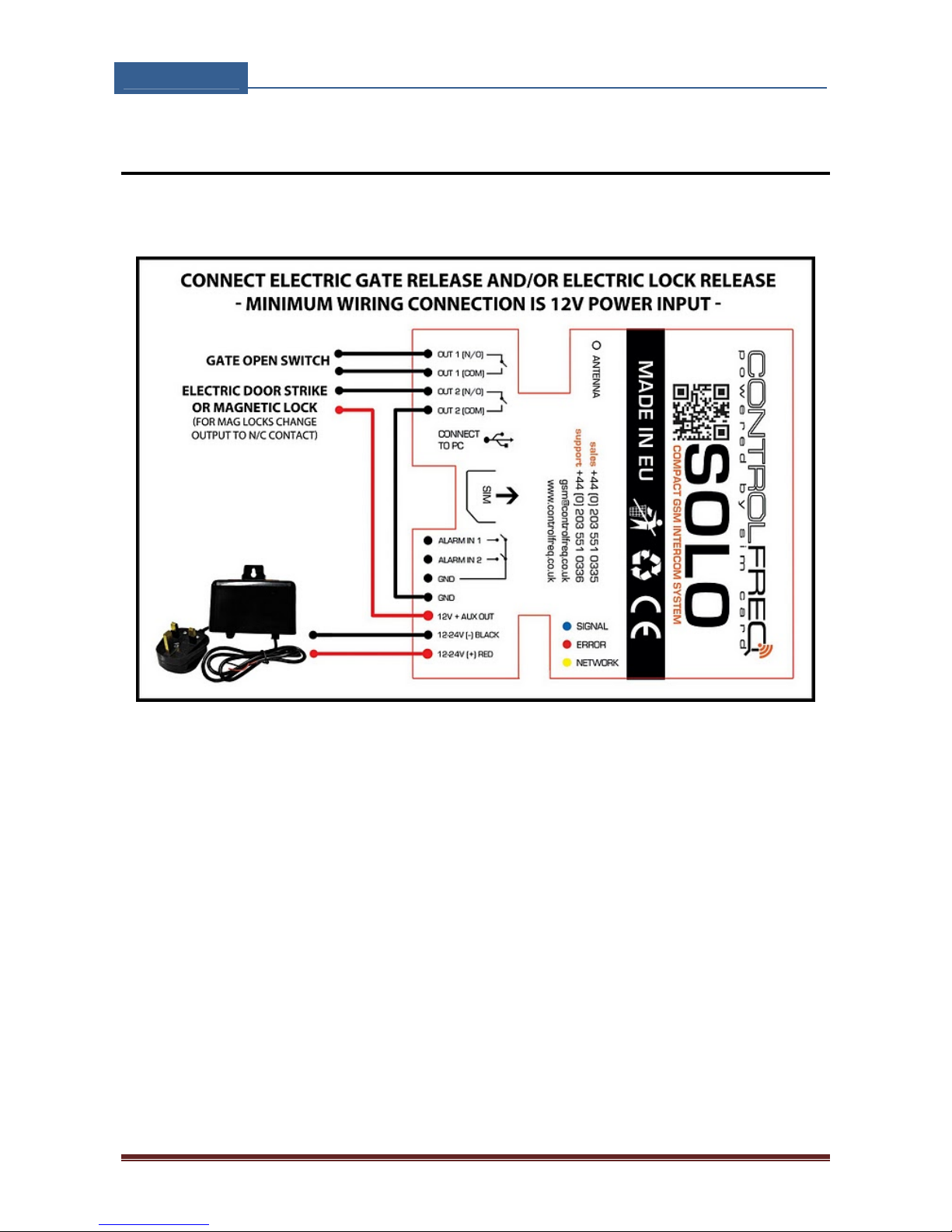
7 CONNECTION DIAGRAM
Before connection the QUICK-FIT GSM please take a look at connection diagram.
Figure 1: QUICK-FIT GSM Connection diagram
Page 12

QUICK‐FITGSM
INSTALLATIONMANUAL
Page12
8 PROGRAMMING QUICK-FIT GSM
QUICK-FIT GSM device supports different types of programming:
⇒ To program QUICK-FIT GSM parameters put the SIM card into your personal GSM
phone. Add programming parameters in SIM Card “Phone Book”.
⇒ You can program QUICK-FIT GSM remotely by SMS command.
⇒ You can program QUICK-FIT GSM with USB key and SIM manager (optional).
Page 13
QUICK‐FITGSM
INSTALLATIONMANUAL
Page13
9 THE QUICK-FIT GSM PARAMETERS
To support versatile functionality of QUICK-FIT GSM different parameters are used. The
parameters are divided in logical sections and are described in the following chapters.
9.1 ALARM SUPPORT
Alarm reporting is supported by group of different parameters. First section is used to
define the relations needed for alarm to be trigged. The second section is used to report
alarm.
9.1.1 ALARM TRIGGERING
Parameters are used to control (filter) the triggering of the alarm inputs.
9.1.1.1 IN parameter
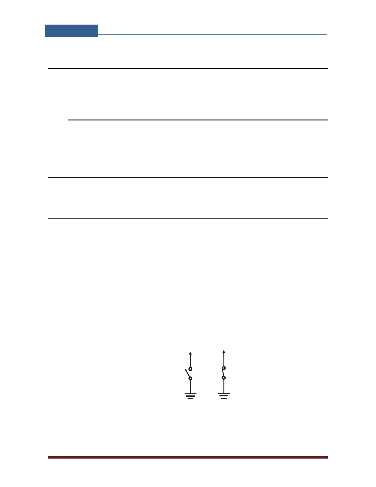
Alarm and reset input can be triggered in 2 different ways. The status of the input can
either be normal closed (N.C) or normal open (N.O.) trigged with GND.
When you need the input feedback information it is possible to receive SMS when input
returns from alarm to normal position. To receive return SMS use IN setting 4 and 5.
⇒ IN = 0 – Normal Open – triggered with negative voltage (GND)
⇒ IN = 1 – Normal Close – breaking negative or positive voltage loop
⇒ IN = 2 – Not in use
⇒ IN = 3 – Not in use
⇒ IN = 4 = IN = 0 + input reset SMS
⇒ IN = 5 = IN = 1 + input reset SMS
⇒ IN = 6 – Not in use
GND
INPUT 1-4
N.O.
contact
GND
1-4INPUT
N.C.
contact
Figure 2: Input Connection diagram
Page 14
QUICK‐FITGSM
INSTALLATIONMANUAL
Page14
9.1.1.2 ID parameter
ID parameter determines time period of the pulse length to trigger the alarm. The pulse
time can be from 0,5 seconds to 9999 seconds. The default time is 0,5 seconds when the
parameter value is 0.
9.1.1.3 DD parameter
This parameter is used to define the delay between the time that alarm input is trigged
and the time that alarm is reported.
9.1.1.4 Table of parameters
Name Comment
IN1 Mode of operation for input 1
IN2 Mode of operation for input 2
IN3 Mode of operation for input 3
IN4 Mode of operation for input 4
ID1 Input time integration delay on input 1
ID2 Input time integration delay on input 2
ID3 Input time integration delay on input 3
ID4 Input time integration delay on input 4
DD1 Time delay for alarm reporting on input 1
DD2 Time delay for alarm reporting on input 2
DD3 Time delay for alarm reporting on input 3
DD4 Time delay for alarm reporting on input 4
Table 1: IN, ID and DD parameters
Example:
♦ Direct programming on the SIM card
QUICK-FIT GSM PROGRAMMING TABLE
SIM CARD PHONE BOOK
Name Number Description
IN1 0 Alarm activated by connecting to GND
IN2 4 Alarm activated by connecting to GND + RST SMS
ID1 10
Input 1 has to be valid for 10 second to trigger the
alarm
ID2 0
Input 2 has to be valid for 0,5 second to trigger the
alarm
DD1 0 Reporting of the alarm on input 1 is delayed by 0s
DD2 15 Reporting of the alarm on input 1 is delayed by 15s
Table 2: IN, ID, DD parameters example
Page 15
QUICK‐FITGSM
INSTALLATIONMANUAL
Page15
♦ Remote programming by SMS
;IN1=0;IN2=4;ID1=10;ID2=0;DD1=0;DD2=15;
9.1.2 REMOTE REPORTING ALARM EVENTS
Parameters used to define the way to report the alarm event.
NOTE
QUICK-FIT GSM device send SMS messages for reporting alarm events.
9.1.2.1 TN parameter
Telephone numbers for remote alarm reporting are listed as TN parameters. Remote
alarm reporting on QUICK-FIT GSM is done via SMS messages.
9.1.2.2 LN parameter
This parameter is used to link alarm event from inputs or any other source to the
telephone numbers from TN list.
9.1.2.3 LOT parameter
LOT parameter is used to define the time control for voice calls. The start of voice
connection starts the LOT timer. If the voice connection is still ON when the LOT timer
expires QUICK-FIT GSM disconnects voice connection.
9.1.2.4 Table of parameters
Name Comment
TN1 1st telephone number
TN2 2nd telephone number
TN3 3rd telephone number
TN4 4th telephone number
TN5 5th telephone number
LN1 Input & telephone No. linking for 1st alarm input (TN1 –
TN5)
LN2 Input & telephone No. linking for 2nd alarm input (TN1 –
TN5)
LN3 Input & telephone No. linking for 3nd alarm input (TN1 –
TN5)
LN4 Input & telephone No. linking for 3nd alarm input (TN1 –
TN5)
LN5 Periodic test SMS. No. linking (TN1 – TN5)
LN6 SIM card refill. No. linking (TN1 – TN5)
Page 16
QUICK‐FITGSM
INSTALLATIONMANUAL
Page16
LN7 NAC list. No. linking (TN1 – TN5) ( see note)
LN8 Log status. No. linking (TN1 – TN5)
LOT Time out for GSM connection.
Table 3: Remote alarm reporting parameters
Note:
When telephone number (calling or messaging QUICK-FIT GSM) is not on the CLIP list, not
acknowledge event occurs (NAC). The telephone number responsible for this event can
be send to TN user for notification.
Example:
♦ Direct programming on the SIM card
QUICK-FIT GSM PROGRAMMING TABLE
SIM CARD PHONE BOOK
Name Number Description
TN1 042376678 1st telephone number
LN1 13 Input 1 reports alarm to TN1 & TN3
LN2 1234 Input 2 reports alarm to TN1 & TN 2 & TN3 & TN4
LN7 1
NAC event sent to TN1
LOT 60
Voice connection stay valid for max of 60s, afte
r
this time
Voice connection breaks
Table 4: Remote alarm reporting example
♦ Remote programming by SMS
;TN1=042376678;LN1=13;LN2=1234;LN7=1;LOT=60;
9.1.3 CONTROLLING OUTPUTS BY DTMF
QUICK-FIT GSM can control the outputs with the use of DTMF. This is very useful function
in the intercom application.
To control the outputs the user must press the combination of 2 digits. First digit is used
to select the output (1 to 4), the second digit is used to activate (1) or deactivate (0)
the output. There is a special case when the user can select for first digit (output
selection) number 0. In this case all outputs control by the same time.
Combination must be pressed in 2s interval, and must be 3s apart to be valid.
NOTE
QUICK-FIT GSM must be in voice connection to support DTMF output control!
Page 17
QUICK‐FITGSM
INSTALLATIONMANUAL
Page17
Example:
DTMF combination Description
00 Deactivate ALL outputs
01 Activate ALL outputs
11 Activate output 1
20 Deactivate output 2
Table 5: DTMF control example
9.2 OUTPUT MANAGEMENT
QUICK-FIT GSM supports the possibility to report alarms from inputs and any other
events locally via 4 outputs. The behavior is defined using next parameters
9.2.1 OS parameter
QUICK-FIT GSM device has 2 dedicated relay and 2 OC transistor supported outputs.
Outputs can be configured to different behavior:
⇒ OS = 0 – Disabled
⇒ OS = 1 – Bi-stable toggle mode
⇒ OS = xxx – Mono-stable pulse mode ( any duration in seconds )
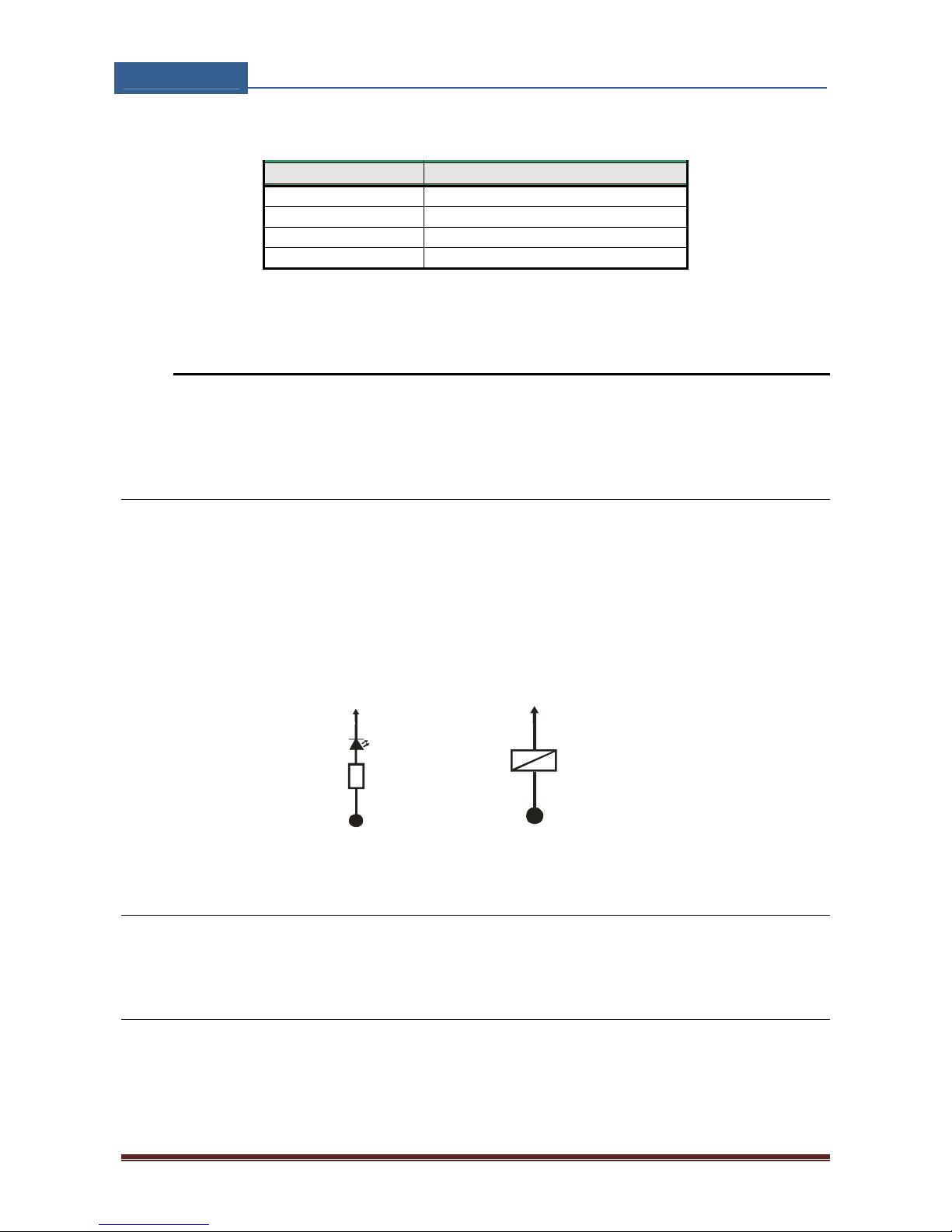
Typical connection for the output:
+12V DC
OUTPUT1-4
R 1K
LED
+12V DC
1-4OUTPUT
RELAY
12V DC
Figure 3: Output Connection diagram
9.2.2 OD parameter
OD parameter is used to link the alarm event directly to output.
9.2.3 OP1, OP2 parameters
Parameters are used to invert the polarity of the outputs.
⇒ 0 – normal (N/O)
⇒ 1 – inverted (N/C)
Page 18
QUICK‐FITGSM
INSTALLATIONMANUAL
Page18
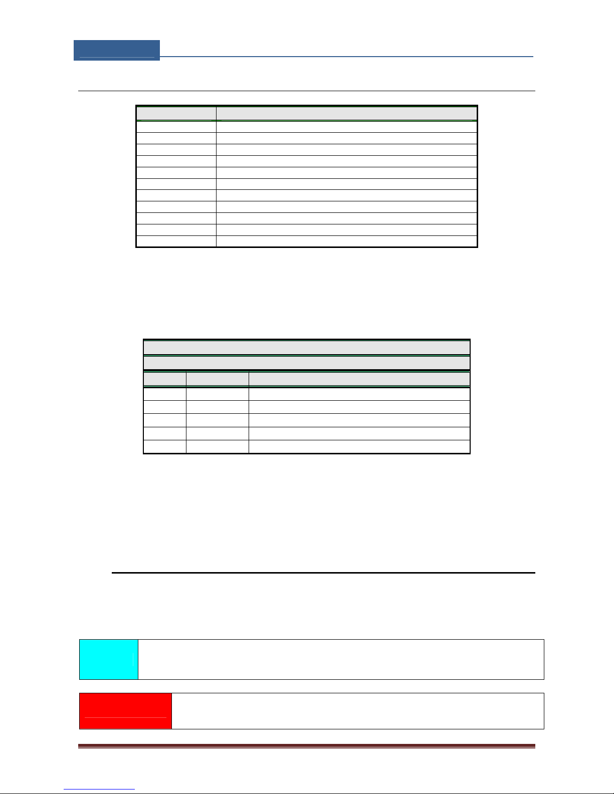
9.2.4 Table of parameters
Name Comment
OS1 Mode of operation for output 1
OS2 Mode of operation for output 2
OS4 Mode of operation for output 3
OS4 Mode of operation for output 4
OD1 Input 1 direct link to outputs
OD2 Input 2 direct link to outputs
OD3 Input 3 direct link to outputs
OD4 Input 4 direct link to outputs
OD5 NAC direct link to outputs
OP1 Invert control for output 1
OP2 Invert control for output 2
Table 6: Output management parameters
Example:
♦ Direct programming on the SIM card
QUICK-FIT GSM PROGRAMMING TABLE
SIM CARD PHONE BOOK
Name Number Description
OS1 1 Bistable toggle mode
OS2 14 Monostable pulse mode ( 14s pusle )
OD1 1 Input 1 activates output 1
OD4 2 Input 2 activates output 2
OP1 1 Output 1 inverted
Table 7: Output management parameters example
♦ Remote programming by SMS
;OS1=1;OS2=14;OD1=1;OD4=2;OP1=1;
9.3 SECURITY LEVEL - SL
SL parameter from 0 to 5 defines which telephone number stored in the phone book
from TN1 – TN5 can enter into programming and remote control of the QUICK-FIT GSM
(dialing the QUICK-FIT GSM phone number or sending the SMS).
NOTE When the SL level is 0, an access to the QUICK-FIT GSM is possible from any
phone!
IMPORTANT
Before any SL number is programmed the QUICK-FIT GSM can accept
Page 19
QUICK‐FITGSM
INSTALLATIONMANUAL
Page19
ALL CALLS. Remote SMS programming and remote controlling is
possible from any phone!
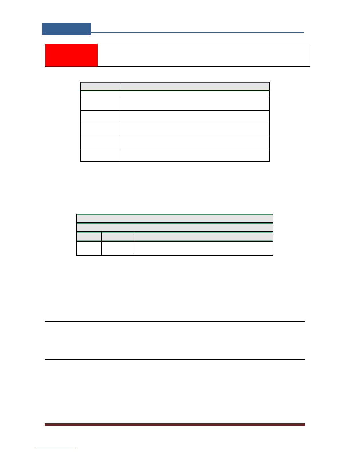
Name / value Comment
SL = 0 All calls and SMS are accepted
SL = 1 Only number stored under parameter TN1 has access to
unit
SL = 2 Numbers stored under parameters TN1 to TN2 have access
to unit
SL = 3 Numbers stored under parameters TN1 to TN3 have access
to unit
SL = 4 Numbers stored under parameters TN1 to TN4 have access
to unit
SL = 5 Numbers stored under parameters TN1 to TN5 have access
to unit
Table 8: SL parameter
Example:
♦ Direct programming on the SIM card
QUICK-FIT GSM PROGRAMMING TABLE
SIM CARD PHONE BOOK
Name Number Description
SL 3
Numbers stored under parameters TN1 to TN3 have
access to unit
Table 9: SL example
♦ Remote programming by SMS
;SL=3;
9.3.1.1 LCV parameter
LCV is used to set the limit for low credit event. If the credit on prepaid SIM cards falls
below this limit SMS is sent.
9.3.1.2 CC1, parameters
Number used to check low credit value. They are provided from the GSM providers.
⇒ CC1 - This method can be used by any GSM provider that supports
Page 20
QUICK‐FITGSM
INSTALLATIONMANUAL
Page20
9.3.1.3 CREF parameters
Parameters are used to find the credit value of the prepaid SIM card. Strings under these
parameters are used to pars the replay message from the GSM provider.
⇒ CREF - Currency reference linked to CC1 parameter
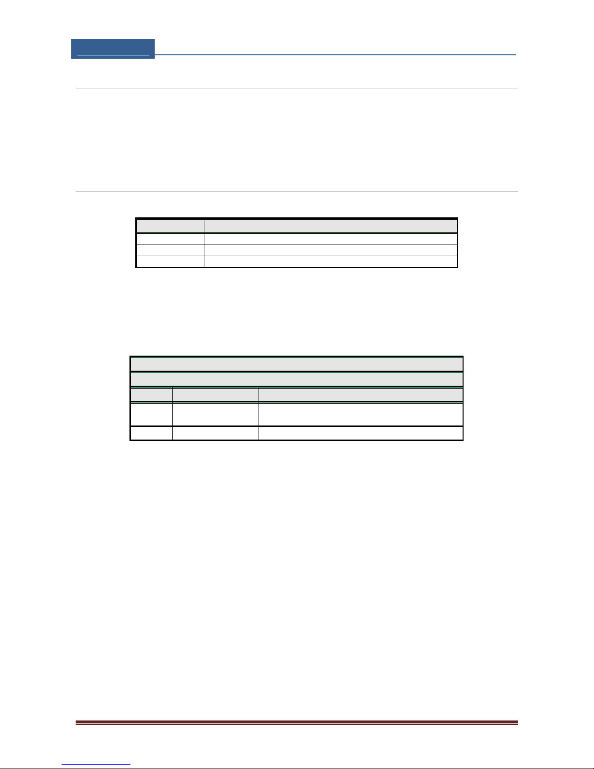
9.3.1.4 Table of parameters
Name Comment
LCV Low credit value, bottom limit for low credit event.
CC1 SMS credit reply string set by network
CREF Currency reference linked to CC1 parameter
Table 10: Prepaid card validity parameters
Example:
♦ Direct programming on the SIM card
QUICK-FIT GSM PROGRAMMING TABLE
SIM CARD PHONE BOOK
Name Number Description
CC1
*1345#
*#100#
Vodafone UK
02 UK
LCV 4 Low credit message will be send below 4
Table 11: Credit example
♦ Remote programming by SMS (for Vodafone UK)
;CC1=*#1345#;CREF#=2;LCV=4;
♦ Remote programming by SMS (for 02 UK)
;CC1=*#100#;CREF.=1;LCV=4;
Page 21

QUICK‐FITGSM
INSTALLATIONMANUAL
Page21
9.4 SET-UP PARAMETERS
Different parameters are used to support versatile functionality of QUICK-FIT GSM.
9.4.1 HTN parameter
Hidden telephone number is a parameter used in order to conceal the telephone number
of the QUICK-FIT GSM device. The default value is set to “1” which means that the
number is displayed.
9.4.2 ESC parameter
Parameter is used to define the input used to cancle the outgoing call from the QUICKFIT GSM device.
9.4.3 UDC parameter
Parameter is used to synchronise QUICK-FIT GSM clock to GSM network clock. User must
enter here the number of the QUICK-FIT GSM SIM card ( Telephone number of QUICK-FIT
GSM device ).
9.4.4 RAN parameter
Parameter is used to provide support for auto-answer options for QUICK-FIT GSM device.
The number defines the numbers of rings needed for QUICK-FIT GSM device to answer
the incoming call. The incoming number must be on the TN list for QUICK-FIT GSM
device to answer.
9.4.5 TST parameter
A test SMS is sent periodically. QUICK-FIT GSM can send the test message in the interval
ranging from 1 hour to 240 hours.
Example:
To send test SMS TST value is set to 12, the numbers linked to “LN5” receive a
test message every 12 hours.
9.4.6 MIC parameter
MIC parameter enables you to change the outgoing sound level on primary microphone
input.
Page 22
QUICK‐FITGSM
INSTALLATIONMANUAL
Page22
9.4.7 SPK parameter
SPK parameter enables you to change the incoming sound level.
9.4.8 ARST parameter
ARST parameter defines periodic of auto restart time (in hours) of the QUICK-FIT GSM
device.
9.4.9 ADF parameter
Parameter is used to define voice refresh function, to prevent blocking of SIM in some
networks.
9.4.10 BUZ parameter
Parameter is used to control buzzer functionality on QUICK-FIT GSM. Buzzer is used to
audio support some events on QUICK-FIT GSM device
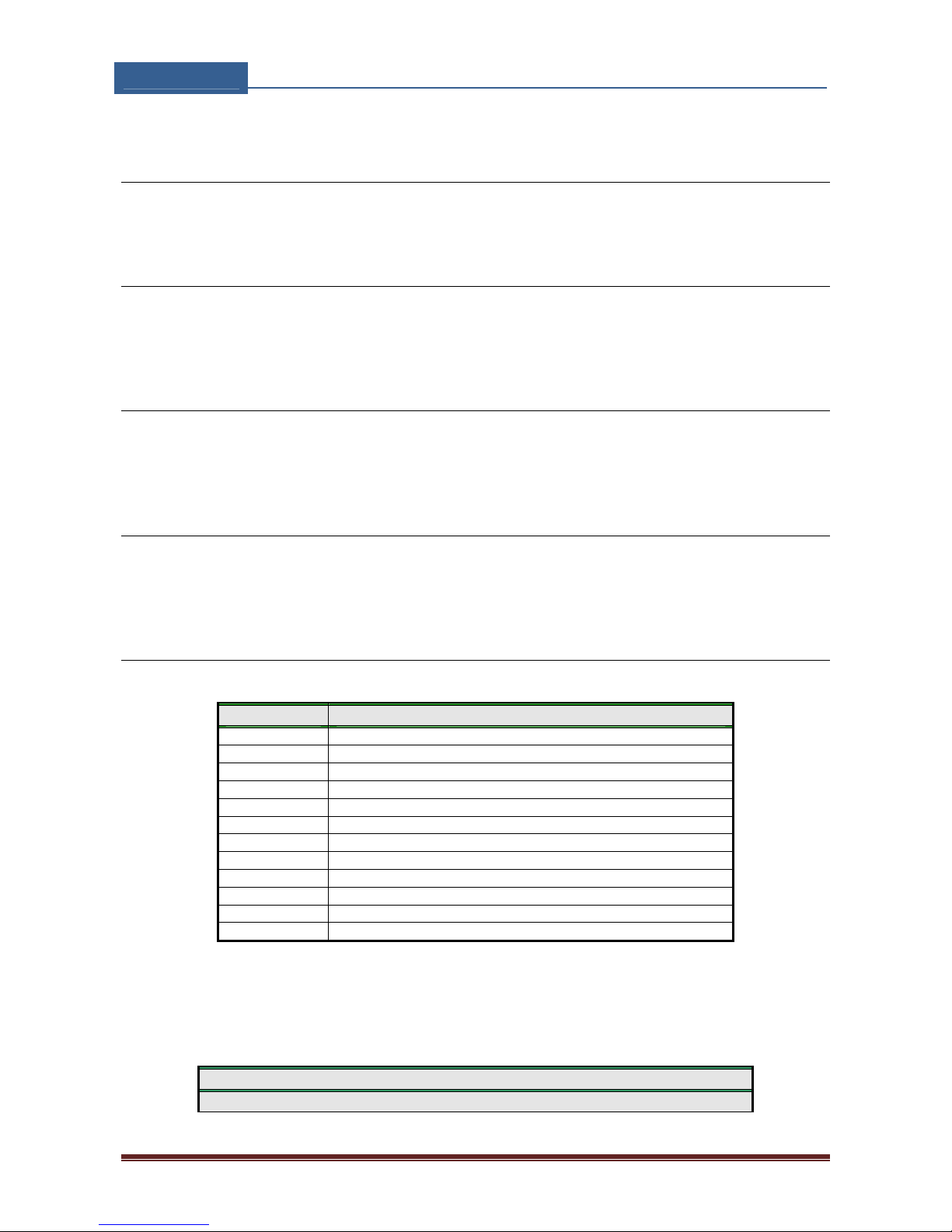
9.4.11 Table of parameters
Name Comment
UDC Tel. number of QUICK-FIT GSM device
ESC Input used as cancle button
RAN Auto answer ring number
HTN Hidden telephone number
TST SMS test time out
MNF Manual GSM provider selection
MIC Microphone volume control
SPK Speaker volume control
ARST Time out control for automatic system restart
ADF Auto dial functionality ( Call TN1 )
LNG Language selection
BUZ Buzzer control
Table 12: Set-up parameters.
Example:
♦ Direct programming on the SIM card
QUICK-FIT GSM PROGRAMMING TABLE
SIM CARD PHONE BOOK
Page 23
QUICK‐FITGSM
INSTALLATIONMANUAL
Page23
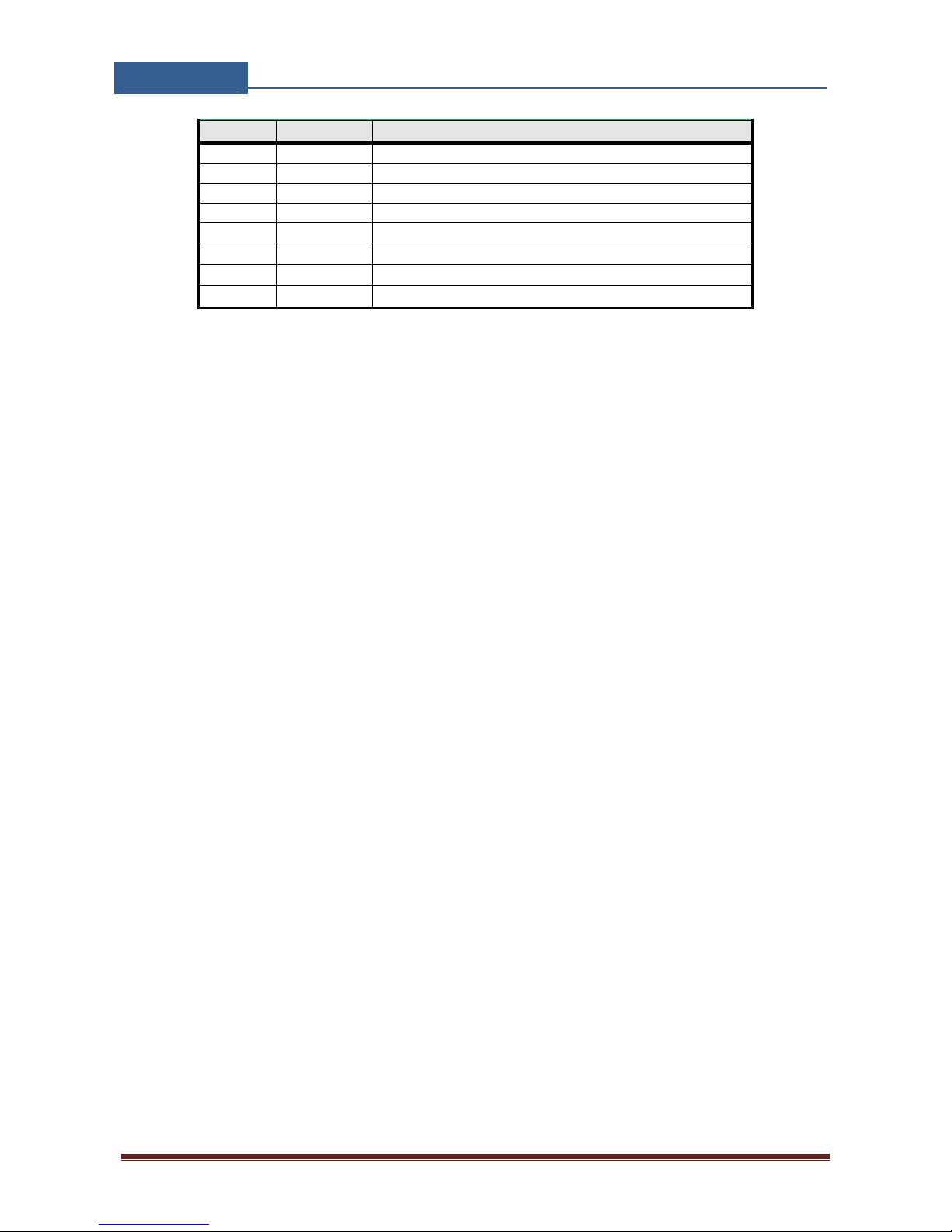
Name Number Description
HTN 0 Hidden telephone number of the QUICK-FIT GSM device
MNF 29340 Manual fixing of the GSM provider (Simobil)
LNG 1 Switch on Italian language
MIC 2 Output sound level
SPK 80 Input sound level
TST 24 24 hours periodic test SMS
BUZ 0 Mute buzzer
ESC 2 Input 2 is used as cancel button
Table 13: Set-up parameters example.
♦ Remote programming by SMS
;HTN=0;MFN=29340;LNG=1;MIC=2;SPK=80;TST=24; BUZ=0;ESC=2;
Page 24
QUICK‐FITGSM
INSTALLATIONMANUAL
Page24
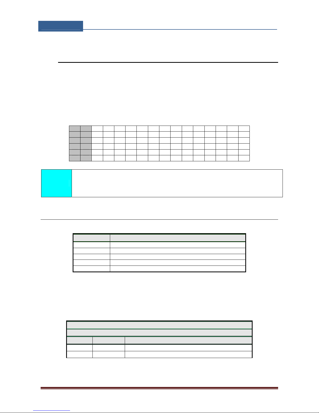
9.5 SMS MESSAGES EDITOR
You can write and send a short SMS message for each alarm input. The default message
is English, but it is possible to change language with LNG parameter. Each message is
built from 3 parts and user can write the first (User Location) and the second (alarm
event) part of the message. Unit adds the third part (alarm event description)
automatically. Language of the 3rd part may be changed by LNG parameter. The
message is stored in the SIM phone book so you should add any number for correct
operation.
1 2 3 4 5 6 7 8 9 10 11 12 13 14 15 16
# 0 U S E R L O C A T I O N
# 1 I N P U T 1
# 2 I N P U T 2
# 3 I N P U T 3
# 4 I N P U T 4
NOTE
Message should not be longer than 14 characters! Space is also counted as
one character!
9.5.1 Table of parameters
Name Comment
#0 User location, same for all alarm messages
#1 Input 1, second part of message
#2 Input 2, second part of message
#3 Input 3, second part of message
#4 Input 4, second part of message
Table 14: Message parameters.
Example:
♦ Direct programming on the SIM card
QUICK-FIT GSM PROGRAMMING TABLE
SIM CARD PHONE BOOK
Name Number Description
#0House 1 Location definition
#1Kitchen 1 Alarm input is from the kitchen
Table 15: Message parameters example.
Page 25

QUICK‐FITGSM
INSTALLATIONMANUAL
Page25
♦ Remote programming by SMS
;#0HOUSE=1;#1KITCHEN=1;
9.6 INTERCOM
Intercom functionality is supported by a set of parameters, used to tweak the
functionality to each user needs.
For each button QUICK-FIT GSM incorporates a group of parameters. There are up to 8
groups of parameters.
9.6.1 ATN1 to ATN5 parameters (A, B, C, D, E, F, G, H) call buttons 1 – 8
Parameters are the call numbers for intercom application.
9.6.2 RTNA parameter (A, B, C, D, E, F, G, H) Buttons1 – 8 call trip timer
Parameter defines the ring time time-out. RTNx timer is started when the call button is
pressed. If the RTNx timer expires before the GSM voice connection is established then
QUICK-FIT GSM device calls the next number in XTN1-XTN5 call list.
9.6.3 DTMF auto dial functionality
This function is used to provide a support for QUICK-FIT GSM device to be able select
extended numbers via DTMF command.
9.6.3.1 SDNx parameter
Parameter is used to set the DTMF number in auto self select function.
9.6.3.2 SDDx parameter
Parameter is used to set the delay ( in s ) for sending DTMF number in auto self select
function.
9.6.4 Time zone
Time zone support. When both time limits are sets ( TZSx and TZEx ) time zone
functionality is ON. When the current time is in the limits of the time zone parameters
the button event calls the number from xTN1 to xTN4, else button event calls xTN5.
9.6.4.1 TZSx parameter
Parameter is used to configure the start time for the time zone functionality - 24h time
format.
Page 26
QUICK‐FITGSM
INSTALLATIONMANUAL
Page26
9.6.4.2 TZEx parameter
Parameter is used to configure the end time for the time zone functionality - 24h time
format.
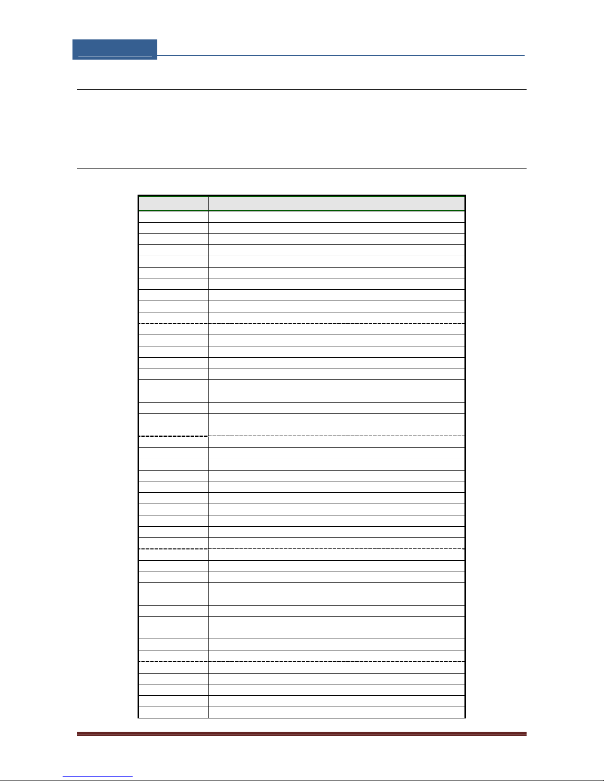
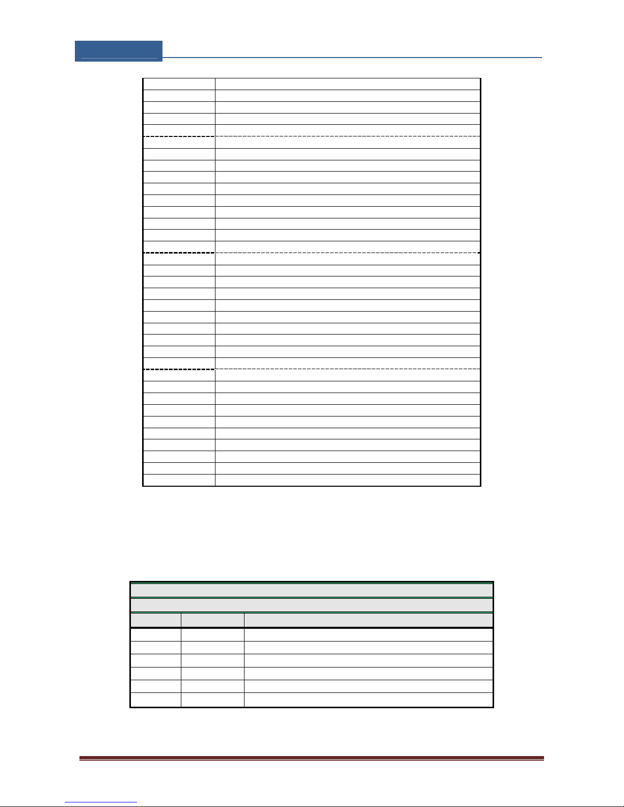
9.6.5 Table of parameters
Name Comment
ATN1 Button 1, Telephone number 1.
ATN2 Button 1, Telephone number 2.
ATN3 Button 1, Telephone number 3.
ATN4 Button 1, Telephone number 4.
ATN5 Button 1, Telephone number 5.
RTNA Button 1, time out control for voice connection.
SDNA Button 1, DTMF number to send.
SDDA Button 1, delay for DTMF number to send.
TZSA Button 1, time zone start period.
TZEA Button 1, time zone end period.
BTN1 Button 2, Telephone number 1.
BTN2 Button 2, Telephone number 2.
BTN3 Button 2, Telephone number 3.
BTN4 Button 2, Telephone number 4.
BTN5 Button 2, Telephone number 5.
RTNB Button 2, time out control for voice connection.
SDNB Button 2, DTMF number to send.
SDDB Button 2, delay for DTMF number to send.
TZSB Button 2, time zone start period.
TZEB Button 2, time zone end period.
CTN1 Button 3, Telephone number 1.
CTN2 Button 3, Telephone number 2.
CTN3 Button 3, Telephone number 3.
CTN4 Button 3, Telephone number 4.
CTN5 Button 3, Telephone number 5.
RTNC Button 3, time out control for voice connection.
SDNC Button 3, DTMF number to send.
SDDC Button 3, delay for DTMF number to send.
TZSC Button 3, time zone start period.
TZEC Button 3, time zone end period.
DTN1 Button 4, Telephone number 1.
DTN2 Button 4, Telephone number 2.
DTN3 Button 4, Telephone number 3.
DTN4 Button 4, Telephone number 4.
DTN5 Button 4, Telephone number 5.
RTND Button 4, time out control for voice connection.
SDND Button 4, DTMF number to send.
SDDD Button 4, delay for DTMF number to send.
TZSD Button 4, time zone start period.
TZED Button 4, time zone end period.
ETN1 Button 5, Telephone number 1.
ETN2 Button 5, Telephone number 2.
ETN3 Button 5, Telephone number 3.
ETN4 Button 5, Telephone number 4.
ETN5 Button 5, Telephone number 5.
Page 27
QUICK‐FITGSM
INSTALLATIONMANUAL
Page27
RTNE Button 5, time out control for voice connection.
SDNE Button 5, DTMF number to send.
SDDE Button 5, delay for DTMF number to send.
TZSE Button 5, time zone start period.
TZEE Button 5, time zone end period.
FTN1 Button 6, Telephone number 1.
FTN2 Button 6, Telephone number 2.
FTN3 Button 6, Telephone number 3.
FTN4 Button 6, Telephone number 4.
FTN5 Button 6, Telephone number 5.
RTNF Button 6, time out control for voice connection
SDNE Button 6, DTMF number to send.
SDDE Button 6, delay for DTMF number to send.
TZSE Button 6, time zone start period.
TZEE Button 6, time zone end period.
GTN1 Button 7, Telephone number 1.
GTN2 Button 7, Telephone number 2.
GTN3 Button 7, Telephone number 3.
GTN4 Button 7, Telephone number 4.
GTN5 Button 7, Telephone number 5.
RTNG Button 7, time out control for voice connection
SDNG Button 7, DTMF number to send.
SDDG Button 7, delay for DTMF number to send.
TZSG Button 7, time zone start period.
TZEG Button 7, time zone end period.
HTN1 Button 8, Telephone number 1.
HTN2 Button 8, Telephone number 2.
HTN3 Button 8, Telephone number 3.
HTN4 Button 8, Telephone number 4.
HTN5 Button 8, Telephone number 5.
RTNH Button 8, time out control for voice connection
SDNH Button 8, DTMF number to send.
SDDH Button 8, delay for DTMF number to send.
TZSH Button 8, time zone start period.
TZEH Button 8, time zone end period.
Table 16: Intercom parameters.
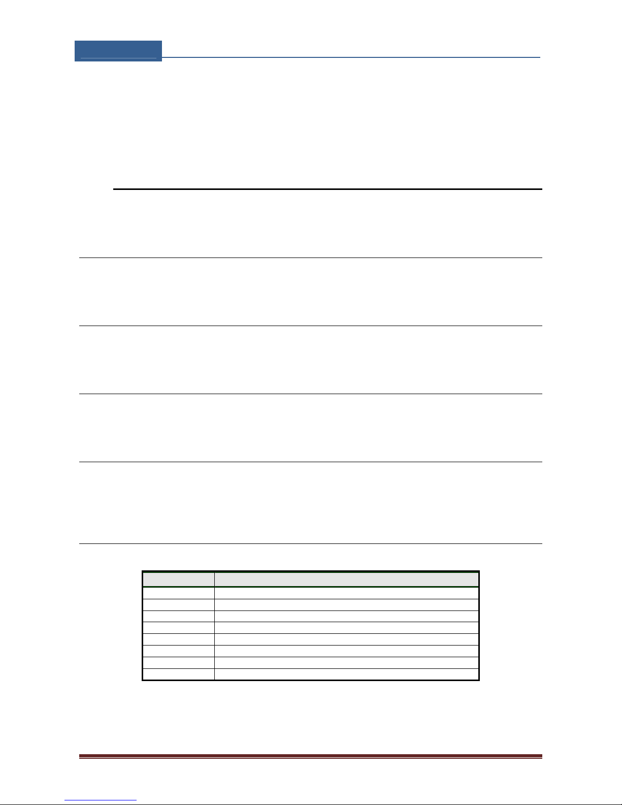
Example:
♦ Direct programming on the SIM card
QUICK-FIT GSM PROGRAMMING TABLE
SIM CARD PHONE BOOK
Name Number Description
ATN1 040713470 Button 1, Telephone number 1.
ATN2 +4474336480 Button 1, Telephone number 2.
RTNA 30 Button 1, time out control for voice connection.
CTN1 040414414 Button 3, Telephone number 1.
CNT2 042340880 Button 3, Telephone number 1.
RTNC 40 Button 3, time out control for voice connection.
Table 17: Intercom parameters example.
Page 28
QUICK‐FITGSM
INSTALLATIONMANUAL
Page28
♦ Remote programming by SMS
;ATN1=040713470;ATN2=+38643364850;RTNA=30;CTN1=040414414;CTN2=04
2340880;RTNC=40;
9.7 CLIP
CLIP is used to provide the “free of charge” options to control the outputs.
9.7.1 CLPEN parameter
Parameter used to enable CLIP functionality.
9.7.2 CLPOU parameter
Parameter used to choose which output will be controlled by the CLIP functionality.
9.7.3 CLPI parameter
This parameter, if set, is a precondition for CLIP function to control the output.
9.7.4 CLP1 … CLP100 parameter
Set of telephone number, which can control the output. The number not on CLP list is
not able to control the output using clip functionality.
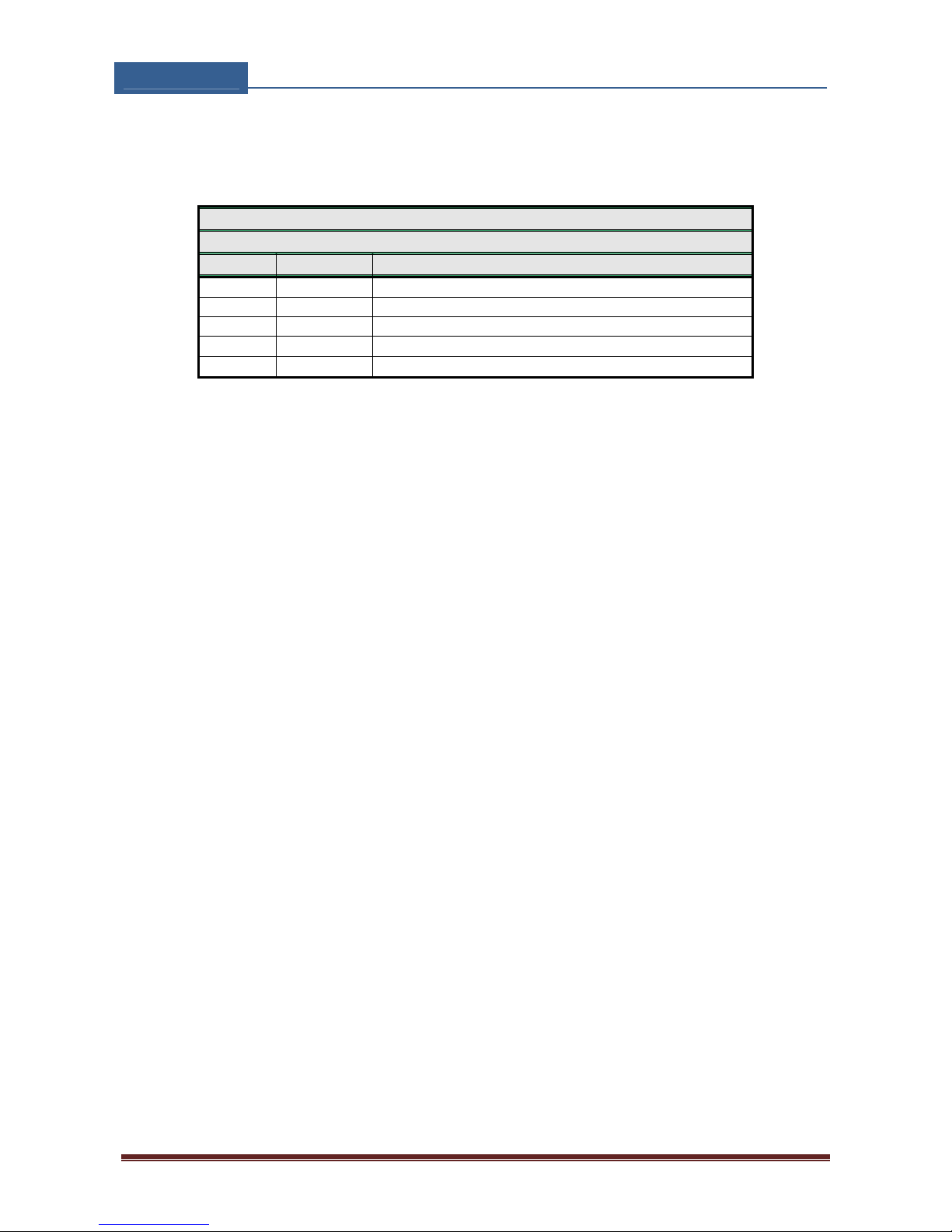
9.7.5 Table of parameters
Name Comment
CLPEN Enable CLIP functionality
CLPOU Control output pin when CLIP event
CLPI CLIP input activation condition
CLP1 CLIP number 1
. .
. .
. .
CLP100 CLIP number 100
Table 18: CLIP parameters.
Page 29
QUICK‐FITGSM
INSTALLATIONMANUAL
Page29
Example:
♦ Direct programming on the SIM card
QUICK-FIT GSM PROGRAMMING TABLE
SIM CARD PHONE BOOK
Name Number Description
CLPEN 1 Enable CLIP functionality
CLPOU 2 CLIP control output 2
CLPI 0 No input activation condition
CLP1 040414414 CLIP number 1
CLP2 042340880 CLIP number 2
Table 19: CLIP parameters example.
♦ Remote programming by SMS
;CLPEN=1;CLPOU=2;CLPI=0;CLP1=040414414;CLP2=042340880;
Page 30
QUICK‐FITGSM
INSTALLATIONMANUAL
Page30
9.8 EVENT LOGGING
QUICK-FIT GSM device support loging of specific events. QUICK-FIT GSM logs CLIP event
and alarm input events.
Log event consist of event type, time and telephone number or input number.
9.8.1 LOGN parameter
Parameter is used for defining the number of events printed out on PLOG request.
9.8.2 LOGI parameter
Parameter is used to define the media used for loging of events on QUICK-FIT GSM. User
can select between nonvolatile memory on QUICK-FIT GSM or select USB to transfer
events directly via USB to PC.
9.8.3 ALC parameter
Parameter is used to control behavior when log on QUICK-FIT GSM is full. User can select
between auto log clear or manual clear of log.
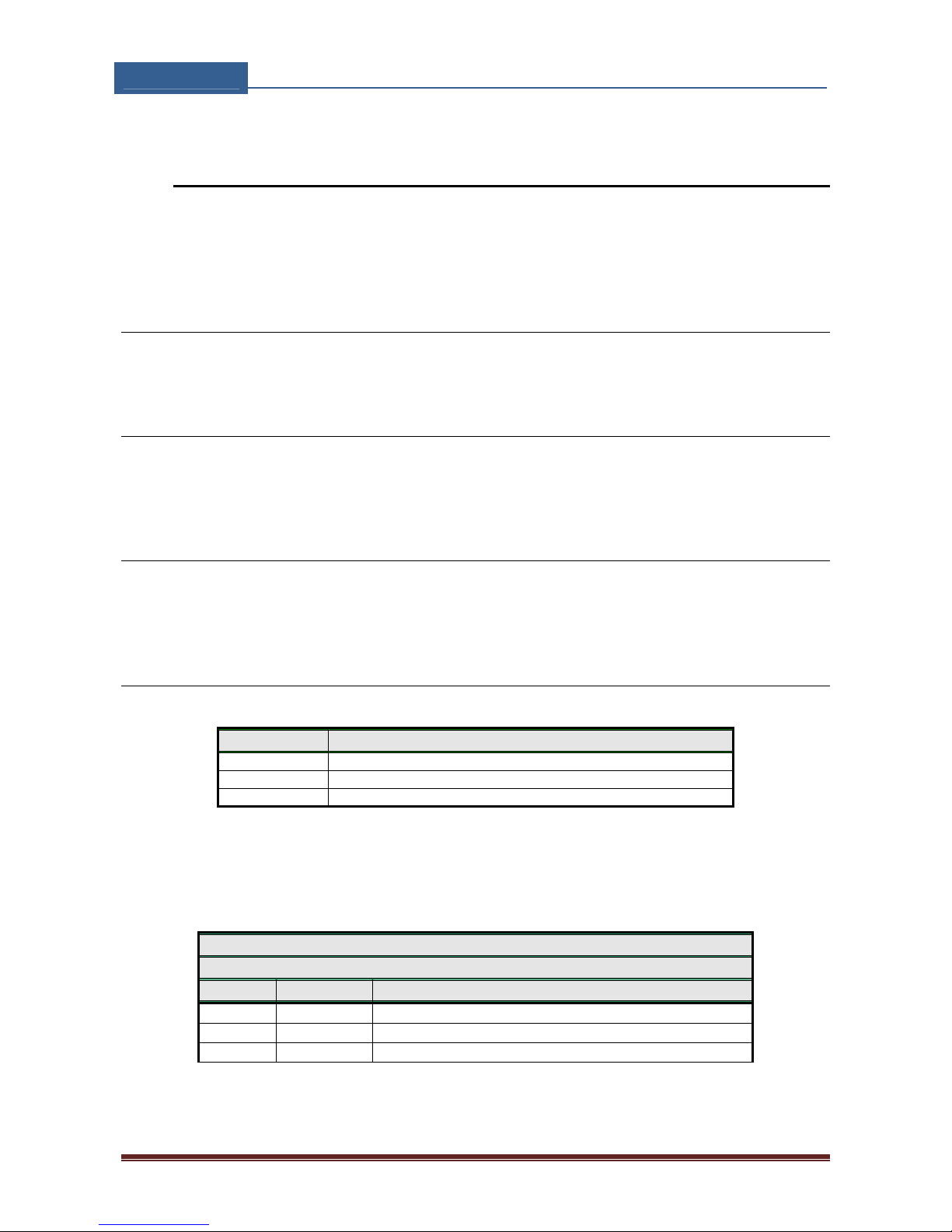
9.8.4 Table of parameters
Name Comment
LOGN Number of log events for printing out
LOGI Log interface
ALC Automatic log clear
Table 20: LOG parameters.
Example:
♦ Direct programming on the SIM card
QUICK-FIT GSM PROGRAMMING TABLE
SIM CARD PHONE BOOK
Name Number Description
LOGN 5 5 log events will be printed out on PLOG command
LOGI 0 Nonvolatile memory on QUICK-FIT GSM
ALC 1 Log is auto cleared when full
Table 21: LOG parameters example.
Page 31

QUICK‐FITGSM
INSTALLATIONMANUAL
Page31
♦ Remote programming by SMS
;LOGN=5;LOGI=0;ALC=1;
9.9 SPECIAL SMS COMMANDS
These commands can only be issued only over SMS message, and are used to control
some special functions of QUICK-FIT GSM device.
9.9.1 ORC command
Command is used to control outputs directly via SMS message
9.9.2 SDCLR command
To clear all data on SIM card SDCLR command is used.
9.9.3 LCRL command
Command clears log on QUICK-FIT GSM device.
9.9.4 CLPCLR command
Command is used to delete all CLP numbers.
9.9.5 MRES command
Command is used to manually restart GSM module on QUICK-FIT GSM device.
9.9.6 SSRES command
Command is used to manually restart QUICK-FIT GSM device.
9.9.7 Table of parameters
Name Comment
ORC1 Control of output 1
ORC2 Control of output 2
ORC3 Control of output 3
ORC3 Control of output 4
SDCLR Delete all SIM content
Page 32
QUICK‐FITGSM
INSTALLATIONMANUAL
Page32
LCRL Delete log on QUICK-FIT GSM device
MRES Manual reset of GSM module
SSRES Manual reset of QUICK-FIT GSM device
Table 22: SMS commands.
Example:
♦ Remote programming by SMS
SMS commad Description
;ORC1=1; Activate output 1
;ORC3=0; Deactivate output 3
;SDCLR; Clear all data on SIM
;LCLR; Delete log on QUICK-FIT GSM device
;MRES; Manual reset of GSM module
;SSRES; Manual reset of QUICK-FIT GSM device
Table 23: SMS commands example.
Page 33

QUICK‐FITGSM
INSTALLATIONMANUAL
Page33
10 PRINT-OUT OF THE PARAMETERS
The user can check the settings of ALL parameters on the QUICK-FIT GSM.
10.1 RECEIVE ALL PARAMETERS (PALL)
By sending this command to QUICK-FIT GSM you receive SMS messages with all
parameters that are currently programmed in the unit:
;PALL;
10.2 CHECK SW REVISION (PSW)
By sending this command to QUICK-FIT GSM you receive SMS messages with current SW
version running on QUICK-FIT GSM device:
;PSW;
10.3 CHECK SIGNAL QUALITY (PSQ)
By sending this command to QUICK-FIT GSM you receive SMS messages with signal quality
QUICK-FIT GSM device is connected to network:
;PSQ;
10.4 RECEIVE TELEPHONE NUMBERS (PTN)
By sending this command to QUICK-FIT GSM you receive SMS message with all currently
programmed telephone numbers (TN1 – TN5):
;PTN;
10.5 RECEIVE LINKS (PLN)
By sending this command to QUICK-FIT GSM you receive SMS message with all currently
programmed links (LN1 –LN8):
;PLN;
10.6 RECEIVE INPUT PARAMETERS (PIN)
By sending this command to QUICK-FIT GSM you receive SMS message with all currently
programmed Input parameters (IN1 – IN4):
;PIN;
Page 34

QUICK‐FITGSM
INSTALLATIONMANUAL
Page34
10.7 RECEIVE INPUT FILTER VALUE (PID)
By sending this command to QUICK-FIT GSM you receive SMS message with all currently
programmed Input filters (ID1 – ID4):
;PID;
10.1 RECEIVE INPUT FILTER VALUE (POD)
By sending this command to QUICK-FIT GSM you receive SMS message with all currently
programmed direct output links (OD1 – OD5):
;POD;
10.2 RECEIVE DELAY BEFORE DIAL VALUE (PDD)
By sending this command to QUICK-FIT GSM you receive SMS message with all currently
programmed Input filters (DD1 – DD4):
;PDD;
10.3 RECEIVE ACCESS TELEPHONE NUMBERS (PSL)
By sending this command to QUICK-FIT GSM you receive SMS message with programmed
SL level:
;PSL;
10.4 RECEIVE OUTPUT PARAMETERS (POS)
By sending this command to QUICK-FIT GSM you receive SMS message with all currently
programmed Outputs parameters (OS1 – OS4):
;POS;
10.5 RECEIVE ALL PROGRAMMED SMS MESSAGES (P#)
By sending this command to QUICK-FIT GSM you receive SMS message with all currently
programmed alarm SMS messages (#0 - #4):
;P#;
10.6 RECEIVE SET UP PARAMETERS VALUE (PPA)
By sending this command to QUICK-FIT GSM you receive SMS message with all currently
programmed Setup parameters (TST, MNF…):
;PPA;
Page 35
QUICK‐FITGSM
INSTALLATIONMANUAL
Page35
10.7 RECEIVE CREDIT PARS PARAMETERS (PCREF)
By sending this command to QUICK-FIT GSM you receive SMS message with all currently
programmed credit parse parameters (CREF, CVODA…):
;PCREF;
10.8 RECEIVE ALL CLIP PARAMETERS (PCLP)
By sending this command to QUICK-FIT GSM you receive SMS message with all currently
programmed CLIP functionality related parameters (CLPEN, CLPOU, CLPI, CLPx):
;PCLP;
NOTE
User can use ;PCLP=x,y; to limit the number of CLIP numbers to be printed.
x = start number
y = end number
Example
;PCLP=1, 30; Prints first 30 CLIP numbers
10.9 RECEIVE INTERCOM BUTTON 1 PARAMATERS (PDEA)
By sending this command to QUICK-FIT GSM you receive SMS message with all currently
programmed button 1 group parameters ( ATN1, ATN2, ATN3, ATN4, ATN5, RTNA, SDNA,
SDDA, TZSA, TZEA ):
;PDEA;
10.10 RECEIVE INTERCOM BUTTON 2 PARAMATERS (PDEB)
By sending this command to QUICK-FIT GSM you receive SMS message with all currently
programmed button 2 group parameters ( BTN1, BTN2, BTN3, BTN4, BTN5, RTNB, SDNB,
SDDB, TZSB, TZEB ):
;PDEB;
10.11 RECEIVE INTERCOM BUTTON 3 PARAMATERS (PDEC)
By sending this command to QUICK-FIT GSM you receive SMS message with all currently
programmed button 3 group parameters ( CTN1, CTN2, CTN3, CTN4, CTN5, RTNC, SDNC,
SDDC, TZSC, TZEC ):
;PDEC;
Page 36

QUICK‐FITGSM
INSTALLATIONMANUAL
Page36
10.12 RECEIVE INTERCOM BUTTON 4 PARAMATERS (PDED)
By sending this command to QUICK-FIT GSM you receive SMS message with all currently
programmed button 4 group parameters ( DTN1, DTN2, DTN3, DTN4, DTN5, RTND, SDND,
SDDD, TZSD, TZED ):
;PDED;
10.13 RECEIVE INTERCOM BUTTON 5 PARAMATERS (PDEE)
By sending this command to QUICK-FIT GSM you receive SMS message with all currently
programmed button 5 group parameters ( ETN1, ETN2, ETN3, ETN4, ETN5, RTNE, SDNE,
SDDE, TZSE, TZEE ):
;PDEE;
10.14 RECEIVE INTERCOM BUTTON 6 PARAMATERS (PDEF)
By sending this command to QUICK-FIT GSM you receive SMS message with all currently
programmed button 6 group parameters ( FTN1, FTN2, FTN3, FTN4, FTN5, RTNF, SDNF,
SDDF, TZSF, TZEF ):
;PDEF;
10.15 RECEIVE INTERCOM BUTTON 7 PARAMATERS (PDEG)
By sending this command to QUICK-FIT GSM you receive SMS message with all currently
programmed button 7 group parameters ( GTN1, GTN2, GTN3, GTN4, GTN5, RTNG,
SDNG, SDDG, TZSG, TZEG ):
;PDEG;
10.16 RECEIVE INTERCOM BUTTON 8 PARAMATERS (PDEH)
By sending this command to QUICK-FIT GSM you receive SMS message with all currently
programmed button 8 group parameters ( HTN1, HTN2, HTN3, HTN4, HTN5, RTNH,
SDNH, SDDH, TZSH, TZEH ):
;PDEH;
10.17 STATE OF THE CREDIT FOR THE PREPAID CARD
By sending this command to QUICK-FIT GSM you receive SMS message with Credit amount
on your prepaid SIM card:
;PCCX;
Where X is the number of programmed prepaid card provider.
Page 37

QUICK‐FITGSM
INSTALLATIONMANUAL
Page37
10.18 STATE OF THE OUTPUTS (PORC)
By sending this command to QUICK-FIT GSM you receive SMS message with current
outputs state.
;PORC;
10.19 MANUAL GSM MODULE RETARD (MRES)
By sending this command to QUICK-FIT GSM shuts down GSM module and after a few
second it switches the power of the GSM module ON again. The unit reboots all
parameters from the SIM card.
;MRES;
10.20 RECEIVE STATUS OF INPUTS (INS)
By sending this command to QUICK-FIT GSM you receive SMS message with current input
state.
;INS;
10.21 RECEIVE QUICK-FIT GSM LOG
By sending this command to QUICK-FIT GSM you receive SMS message with log on QUICKFIT GSM device.
;PLOG;
Page 38
QUICK‐FITGSM
INSTALLATIONMANUAL
Page38
11 CHANGING PARAMETERS USING THE SMS COMMAND
All programming parameters for QUICK-FIT GSM can also be sent by SMS command. Each
SMS command should start and stop with semicolon. If the confirmation SMS is needed,
put “+” at the beginning of the command SMS.
The first SMS is SMS with telephone numbers (TN1 – TN4). If you would like to check
which telephone numbers are programmed in QUICK-FIT GSM please use the following
command:
;PTN;
Return SMS is (example):
;TN1=0;TN2=0;
If you would like to enter telephone numbers in to QUICK-FIT GSM you can use the
following example:
;TN1=040713470;TN2=+38643364850;
If you would like to receive confirmation SMS write “+” before SMS command:
;+TN1=040713470;TN2=+38643364850;
Return SMS from QUICK-FIT GSM is:
;TN1=040713470;TN2=+38643364850;
NOTE
You can use the same programming procedure for all parameters.
It is also possible to change different parameters with one SMS. Consider that the SMS
message should not be longer than 160 characters (included space characters).
If you would like to change the following parameters TN1, IN1, IN2, OS1, OS2; ID1, LN1
and CRE and would like to receive confirmation SMS, try next example:
;+TN1=07796178765;IN1=1;IN2=1;OS1=15;OS2=1;ID1=120;LN1=1;
Send SMS message to QUICK-FIT GSM telephone number and in a few seconds you receive
SMS message from QUICK-FIT GSM. The sentence of the SMS must be the same as the one
you have sent to QUICK-FIT GSM before.
Page 39
QUICK‐FITGSM
INSTALLATIONMANUAL
Page39
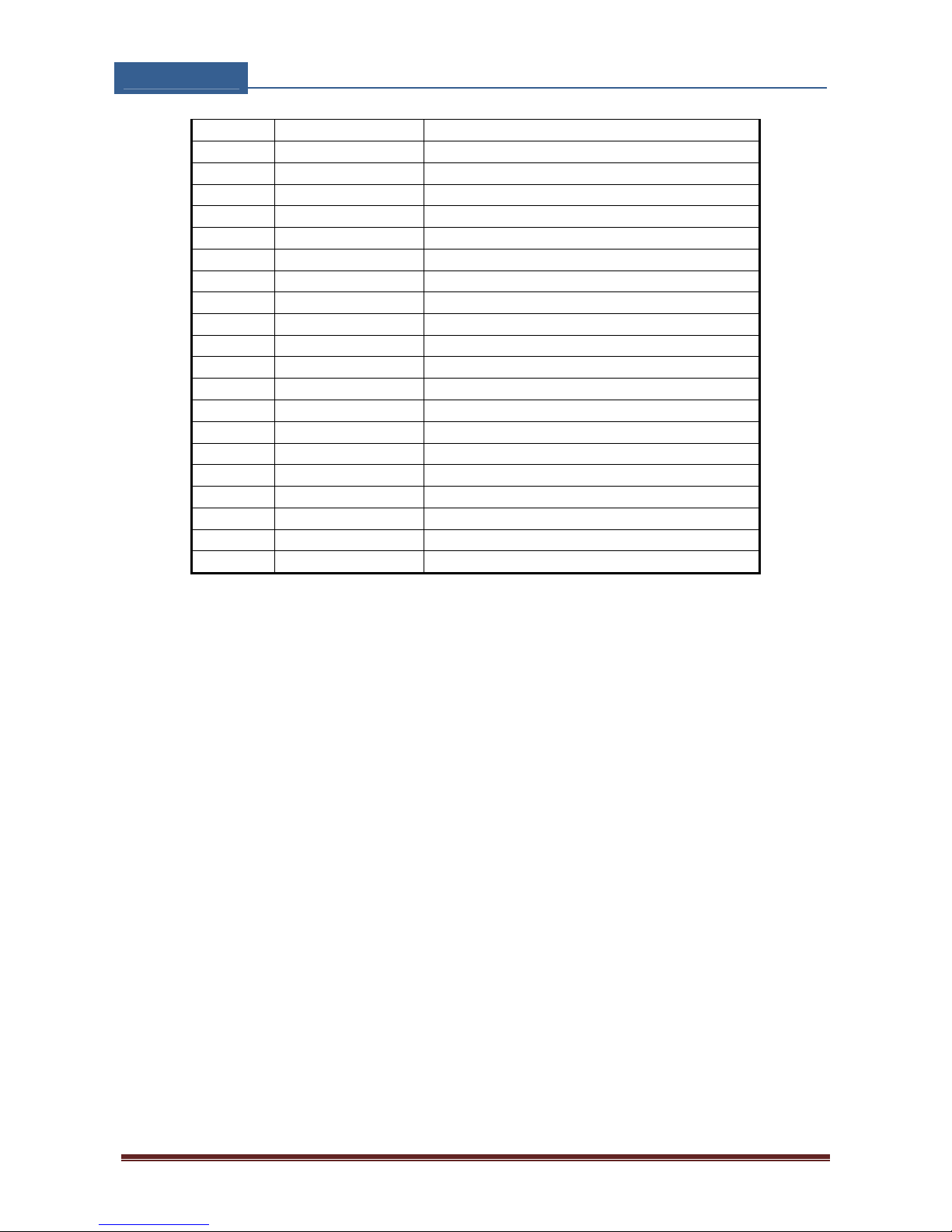
12 DEFAULT SETTINGS ON QUICK-FIT GSM
QUICK-FIT GSM PROGRAMMING TABLE
Name Default Value Short Description
TN1 Empty
Telephone number 1
TN2 Empty
Telephone number 1
TN3 Empty Telephone number 2
TN4 Empty Telephone number 3
TN5 Empty Telephone number 4
IN1 0 Input 1 control
IN2 0 Input 2 control
IN3 0 Input 3 control
IN4 0 Input 4 control
OS1 5 Output 1 mode
OS2 5 Output 2 mode
OS3 5 Output 3 mode
OS4 5 Output 4 mode
OD1 1 Input 1 direct output link
OD2 0 Input 2 direct output link
OD3 0 Input 3 direct output link
OD4 0 Input 4 direct output link
OD5 0 NAC direct output link
LN1 Empty Input 1, link to tel. numbers
LN2 1 Input 2, link to tel. numbers
LN3 Empty Input 3, link to tel. numbers
LN4 1 Input 4, link to tel. numbers
LN5 Empty Periodic SMS text, link to tel. numbers
LN6 Empty SIM card refill, link to tel. numbers
LN7 Empty NAC, link to tel. numbers
LN8 Empty LOG full, link to tel. numbers
ID1 1 Input 1 delay filter on input
ID2 120 Input 2 delay filter on input
ID3 1 Input 3 delay filter on input
ID4 1 Input 4 delay filter on input
DD1 0 Input 1 delay before dialing
DD2 0 Input 2 delay before dialing
DD3 0 Input 3 delay before dialing
DD4 0 Input 4 delay before dialing
SL 0 Security level
#0 “User Location” SMS main head text
#1 “Input1” SMS input 1 text
#2 “Input2” SMS input 2 text
#3 “Input3” SMS input 3 text
#4 “Input4” SMS input 4 text
CC1 Empty Check credit Num 1
Page 40

QUICK‐FITGSM
INSTALLATIONMANUAL
Page40
CC2 Empty Check credit, TIM Italy
CC3 Empty Check credit, Vodafone Italy
ESC 0 Input used as cancel button
UDC Empty Tel. number of QUICK-FIT GSM device
HTN 1 Hidden telephone number
RAN 0 Auto answer ring number
SCV 0 SIM card time validity
TST 24 Periodic test SMS timeout
MNF 0 Network connection type
MIC 15 Microphone volume setting ( 0 - 40 )
MUT 0 Mute functionality
SPK 10 Speaker volume setting ( 0 - 20 )
LCV 4 Low credit value
LNG 0 Language selection
LOT 90 Connection time out value
LOGN 5 Number of log events for printing out
LOGI 0 Log interface
ALC 1 Automatic log clear
ADF 90 Auto dial functionality ( Call TN1 )
ARST 0 Automatic reset timeout
CREF “EUR” Parse text( contact support )
CTIM “EURO” Parse text( contact support )
CVODA “DISPON. E.” Parse text( contact support )
OP1 1 Output invert 1
OP2 1 Output invert 2
BUZ 1 Buzzer control
SPO 1 SIM card starting position
CLPEN 1 Enable CLIP functionality
CLPOU 1 Control output pin when CLIP event
CLPI 0 CLIP input activation condition
CLP1 Empty CLIP number 1
. .
. .
. .
CLP100 Empty CLIP number 100
ATN1 Empty Button 1, Telephone number 1
ATN2 Empty Button 1, Telephone number 2
ATN3 Empty Button 1, Telephone number 3
ATN4 Empty Button 1, Telephone number 4
ATN5 Empty Button 1, Telephone number 5
RTNA 25 Ring time, Button 1
SDNA 0 DTMF number to send
SDDA 0 Delay for DTMF to send
TZSA 0 Time zone start interval
TZEA 0 Time zone end interval
BTN1 Empty Button 2, Telephone number 1
BTN2 Empty Button 2, Telephone number 2
Page 41

QUICK‐FITGSM
INSTALLATIONMANUAL
Page41
BTN3 Empty Button 2, Telephone number 3
BTN4 Empty Button 2, Telephone number 4
BTN5 Empty Button 2, Telephone number 5
RTNB 25 Ring time, Button 2
SDNB 0 DTMF number to send
SDDB 0 Delay for DTMF to send
TZSB 0 Time zone start interval
TZEB 0 Time zone end interval
CTN1 Empty Button 3, Telephone number 1
CTN2 Empty Button 3, Telephone number 2
CTN3 Empty Button 3, Telephone number 3
CTN4 Empty Button 3, Telephone number 4
CTN5 Empty Switch 3, Telephone number 5
RTNC 25 Ring time, Button 3
SDNC 0 DTMF number to send
SDDC 0 Delay for DTMF to send
TZSC 0 Time zone start interval
TZEC 0 Time zone end interval
DTN1 Empty Button 4, Telephone number 1
DTN2 Empty Button 4, Telephone number 2
DTN3 Empty Button 4, Telephone number 3
DTN4 Empty Button 4, Telephone number 4
DTN5 Empty Button 4, Telephone number 5
RTND 25 Ring time, Button 4
SDND 0 DTMF number to send
SDDD 0 Delay for DTMF to send
TZSD 0 Time zone start interval
TZED 0 Time zone end interval
ETN1 Empty Button 5, Telephone number 1
ETN2 Empty Button 5, Telephone number 2
ETN3 Empty Button , Telephone number 3
ETN4 Empty Button 5, Telephone number 4
ETN5 Empty Button 5, Telephone number 5
RTNE 25 Ring time, Button 5
SDNE 0 DTMF number to send
SDDE 0 Delay for DTMF to send
TZSE 0 Time zone start interval
TZEE 0 Time zone end interval
FTN1 Empty Button 6, Telephone number 1
FTN2 Empty Button 6, Telephone number 2
FTN3 Empty Button 6, Telephone number 3
FTN4 Empty Button 6, Telephone number 4
FTN5 Empty Button 6, Telephone number 5
RTNF 25 Ring time, Button 6
SDNF 0 DTMF number to send
SDDF 0 Delay for DTMF to send
TZSF 0 Time zone start interval
Page 42
QUICK‐FITGSM
INSTALLATIONMANUAL
Page42
TZEF 0 Time zone end interval
GTN1 Empty Button 7, Telephone number 1
GTN2 Empty Button 7, Telephone number 2
GTN3 Empty Button 7, Telephone number 3
GTN4 Empty Button 7, Telephone number 4
GTN5 Empty Switch 7, Telephone number 5
RTNG 25 Ring time, Button 7
SDNG 0 DTMF number to send
SDDG 0 Delay for DTMF to send
TZSG 0 Time zone start interval
TZEG 0 Time zone end interval
HTN1 Empty Button 8, Telephone number 1
HTN2 Empty Button 8, Telephone number 2
HTN3 Empty Button 8, Telephone number 3
HTN4 Empty Button 8, Telephone number 4
HTN5 Empty Button 8, Telephone number 5
RTNH 25 Ring time, Button 8
SDNH 0 DTMF number to send
SDDH 0 Delay for DTMF to send
TZSH 0 Time zone start interval
TZEH 0 Time zone end interval
Table 24: QUICK-FIT GSM default settings.
Page 43
QUICK‐FITGSM
INSTALLATIONMANUAL
Page43
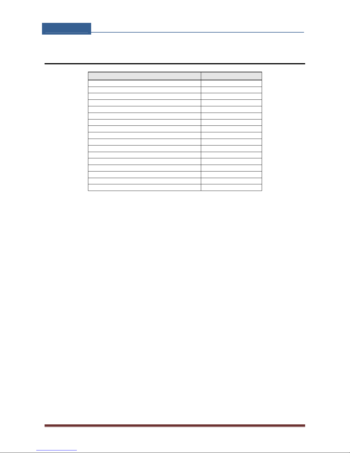
13 TECHNICAL SPECIFICATION
Description Value
Power Supply 13,8 - 24V AC/DC
Current consumption - peak 2A
Current consumption - transmitting mode 250mA
Current consumption - idle mode 75mA
Tri band GSM module (QUAD optional) 900/1800 MHz *
PCB dimensions 106 × 89 mm
Unit dimensions 118 × 170 × 60 mm
Call buttons Up to 8
Antenna SMA 1
Weight 810 gr.
Alarm inputs 2 + 2
Alarm outputs (relay) 2
Alarm outputs (open collector) 2
12V DC Power Supply input Y
12/24V AC/DC Power Supply input Y
Anti-tamper protection optional
* Quad Band GSM module optional
Page 44

QUICK‐FITGSM
INSTALLATIONMANUAL
Page44
14 CONTROL FREQ GSM
Office & Showroom
Omnibus House
39 - 41 North Road
London, N7 9DP
United Kingdom
Sales +44(0)203 551 0335
Support +44(0)203 551 0336
Email: [email protected]
Webshop: www.controlfreq.co.uk
 Loading...