


Reference/Instruction Manual
CONTROL
3228-A/3229-A
TAPE
CONTROLLER
MAGNETIC
DATA@

60100300
Record
of
Revisions
REVISION
A
B
C
(4-12-65)
D
(6-7-65)
Addition
of 2 Parts
Incorporation
the
Product
manual
Table
II -32,
11-45,
III-9,
Updated
obsoletes
of
Contents
II -
33,
II-47,
A-11
Parts
NOTES
Lists
of
Change
Designation
all
(iii),
II -35,
11-49,
and
A-13
List
II -37,
II-51,
(pages
as
Order
to
3228/3229 -A04.
previous
1-1,
II -39,
II
revised.
C-1
Appendices
893
O.
editions.
1-11
through
II -41,
- 5 3,
II-55,
through
C
which
1-13,
II -42,
11-
C-6).
and
D.
advanced
This
11-31,
II
- 4 3 ,
62,
111-4,
Pub.
No.
1965
Control
in
60100300
Data
the
United
Corporation
States
of
America
June,
©
1965,
Printed
Address
manual
Control
Technical
4201
St.
or
use
this
book.
comments
to:
Data
North
Paul,
Comment
concerning
Corporation
Publications
Lexington
Minnesota
Sheet
Department
Avenue
55112
in
back
this
of

CONTENTS
Part
Section
Section
Physical
Functional
Section
Switches
Section
Section
Section
Section
Register
Register
Reply
Register
I.
Description
1.
Introduction
2.
Description
Description
Description
Clear
Connect
Status
Select
Function
Format
Interrupt
Information
Data
Conversions
3.
Operation
and
Equipment
Longitudinal
Write
Vertical
Parity
Interrupt
BCD
Part
II.
1.
Connect
2.
Function
3.
Function
(Format)
4.
Information
Transfers
Transfers
Transfers
and
Codes
Transfer
Indicators
Selection
Parity
Theory
Selection
Operation
Transfer
During
During
During
Operation
Switch
of
Operation
Write
Write
Read
I-I
1
....
4
1-4
1-4
1-5
1-5
1-7
1-8
1-10
1-11
1-12
1-16
1-16
1-16
1-16
1-16
1-17
1-17
II-I
II-5
II-I0
II-21
II-21
II-26
II-26
Write
(First
Write
(N
ot
Write
(Last
Write
(Non-Stop)
Write
(Write
Read
(First
Read
(Not
Read
Sequence
Read
Sequence
Reverse
Sequence
Suppress
Operation
Section
Skip
Write
Search
Search
Backspace
Rewind
Rewind
Section
Interrupt
Status
Lost
Write
Lost
Operation
Output
Operation
First
or
Operation
Output
Operation
Operation
Sequence
Word)
Sequence
Last
Sequence
Word)
Sequence
Sequence
Reply)
Operation
Two
Operation
First
Operation
(End
Operation
(Not
Read
Sequence
Frames)
Sequence
Two
Frames)
Termination
of
Termination
at
Operation
Record)
End
Assembly/Disassembly
Sequence
5.
Function
Operation
Directives
Bad
Spot
File
Mark
Forward
Backward
to
to
Unload
6.
Program
Conveniences
Function
Data
Condition
Data
During
Read
Output
of
File
File
During
Word)
Record)
Motion
Mark
Mark
II-31
II
- 31
II-32
II-32
II-33
II-41
II-42
II-42
II-43
II-44
II-44
II-53
II-53
II-53
II-53
II-53
II-54
II-54
II-62
II-65
II-66
II-66
iii
Rev.
C

Part
III.
Maintenance
Section
2.
Logic
Cabling
III
-1
Section
Part
1-1
1-2
2-1
2-2
2-3
2-4
2-5
2-6
2-7
2-8
2-
9
2-10
2-11
2-12
2-13
2-14
2-15
2-16
2-17
2-18
2-19
2-20
2-21
2-22
Environmental
1.
Description
1.
3228/3229
3228/3229
System
Part
Connect
Connect
Connect
Function
Function
Function
Clear
Parity
Binary
Clear
Release
Theory
II.
FFs
Operation
Timing
Select
Reply / Reject
Select
and
Mode
Mode
Operation
Operation
Density
200
BPI
Operation
556
BPI
Operation
800
BPI
Operation
Tape
Data
Motion
Reverse
Clear
Transfer
Operation
Reverse
Disassembly
BCD
Conversion
0-to-12
Conversion
Appendix
Appendix
Appendix
Control
Magnetic
FFs
Timing
Release
Operation
Signals
Operation
Control
Care
A.
B.
C.
and
Panel
Tape
of
Operation
Tape
3228/3229
System
3228/3229
Operation
III-l
Section
3.
General
Procedure
Synchronizer / Controller
Operation
Parts
in a 3400
List
FIGURES
1-2
1-2
II-2
II-3
II-4
II-6
II-7
II-8
II-9
II-I0
II
-11
II-12
II-13
II-14
II-15
II-16
II-17
II-18
II-19
II-20
II-22
II-23
II-24
II-24
2-23
2-24
2-25
2-26
2-27
2-28
2-29
2-30
2-;:H
2-32
2-33
2-34
2-35
2-36
2-37
2-38
2-39
2-40
Write
(One
BCD
12-to-0
Assembly
Write
Flow
tion
Word
Flow
tion
ation
Read
Flow
tion
Word
Flow
tion
Read
Flow
tion
Read
Skip
Write
Search
Mark
Search
Mark
Backspace
Rewind
Rewind
Glossary
or
3600
Register
Channel)
Conversion
Conversion
Control
Timing
Chart:
and
Write
Operation
Chart:
and
Write
Timing
Chart:
and
Read
Operation
Chart:
(Not
End
Nonstop
Chart:
(End
of
Nonstop
Bad
Spot
File
Mark
Forward
Backward
Unload
Maintenance
Write
Write
First
Prepara-
Data
Termina-
Nonstop
Read
Read
First
of
Record)
Prepara-
Data
Termina-
Operation
Read
Termina-
Record)
and
Operation
to
File
to
File
Oper-
and
III
-10
II-25
II-28
II-29
II-30
II-35
II-37
II-39
II-45
II-47
II-49
II-
51
II-
55
II-56
II-57
II-58
II-59
II-60
II-61
iv

FIGURES
(Cont'd)
2-41
2-42
1-1
1-2
2-1
2-2
3-1
Part
II
Interrupt
Interrupt
Part
1.
Select
on
Description
Assembly/Disassembly
Order
Function
Codes
Responses
II.
Part
Theory
Sequence
Codes
III.
and
Pin
Cable
Part
Connect
Function
Signal
Output
(Cont'd)
Ready
and
Operation
and
Status
of
Operation
Maintenance
Assignments:
Byte
II-63
II-64
TABLES
1-15
1-17
II-I
II-5
III-
2
2-43
2-44
3-2
3-3
3-4
3-5
3-6
3-7
Inte
rrupt
ation
Interrupt
of
Operation
Signal
Input
Cable
Signal
Signal
Data
I/O
Signal
Control
Data
Channel
Critical
on
End
on
Abnormal
and
Pin
Assignments:
Definitions
and
Pin
Assignments:
Cable
and
Pin
Assignments:
I/O
Cable
Signals
Delay
Table
of
Oper-
End
II-64
II-65
1II-3
1II-4
III-6
1II-7
1II-8
III
-11
v

3228/3229
Magnetic
Tape
Controller

PART
I.
DESCRIPTION
AND
OPERATION
The
CONTROL
for a Control
connected
follows
allows
data
flow.
The
3228
selected
to
the
the
may
and
systems.
rewind
functions
operations.
the
higher
The
603
and
this
manual,
speed.
the
first
If
a
delay
DATA)~
Data
3000
one
3000
method
data
The
inherent
channel
controllers
use
up
operated
The
controller
of
the
Operation
performance
604
tape
any
time a delay
delay
period
period
SECTION
3228/3229
series
series
to
Computer
12 -bit
in
any
select a particular
may
to
four
tape
by
the
exchange
can
read
tape
handler
of
the
controller
604
or
607
handlers
move
period
is
mentioned,
is
for
150
1.
Magnetic
data
3000.
use
all
handlers,
or
free
tape
tape
is
ips
and
INTRODUCTION
Tape
System
channel.
series
peripheral
tape
603,
all
604,
the
3229
of
requests
write
the
using
on
one
controller
603
handlers)
at
75
ips,
mentioned
followed
the
by
second
Controllers
(Figure
The
schem e of
1-
are
2).
equipm
handler
and
tape
or
all
up
to
replies
handler
or
606
and
606,
eight.
the
tape
modifies
or
typical
data
handlers
is a programming
the
606
and
by
itself,
another
for
75
delay
ips.
it
is
input/output
Either
selection
ent.
all
The
The
607
tape
to
at a time.
channel
consideration.
607
at
150
common
period
devices
controller
and
controller
and
synchronizes
tape
handlers.
handlers
the
60X
Search
for
(as
opposed
ips.
to
either
in
parentheses,
can
operation
are
tape
and
other
to
In
tape
be
Whenever a page
refers
Diagrams
):<
to a page
Registered
Manual
trademark
reference
in
the
(Pub.
in
this
3228/3229
No.
60093700),
of
Control
manual
Magnetic
Data
Corporation.
I-I
is
Tape
given
in
parentheses,
Controller
Custom
e.
g. :
(Page
er
Engineering
6),
Rev.
it
C

0507
~
0501
l
6
7
0
6
0 0
BCD
f
0511
LONGITUDINAL
0
5
INT
t
OSlO
Figure
0
4
1-1.
PARITY
0
3
0
VERT
PARI
TY
i
0509
3228/3229
0
2
0
[IJ
0
WRITE
3228
(O
*
t
N
-7)
SWITCH
i
0508
Control
h~~1
~
~~
Panel
L-...J
EQUIPMENT
1
~
__
3_00_0
__
5_E_R_IE~S~,_12_-_B_IT
DATA
CHANNEL
__
~CONTROLLER
*
3228-4
3229-8 TAPE
Figure
TAPE
HANDLER MAXIMUM.
HANDLER MAXIMUM.
1-2.
3228/3229
1-
603,604,606,
TAPE HANDLERS
Magnetic
2
Tape
OR
607
System
3229
*
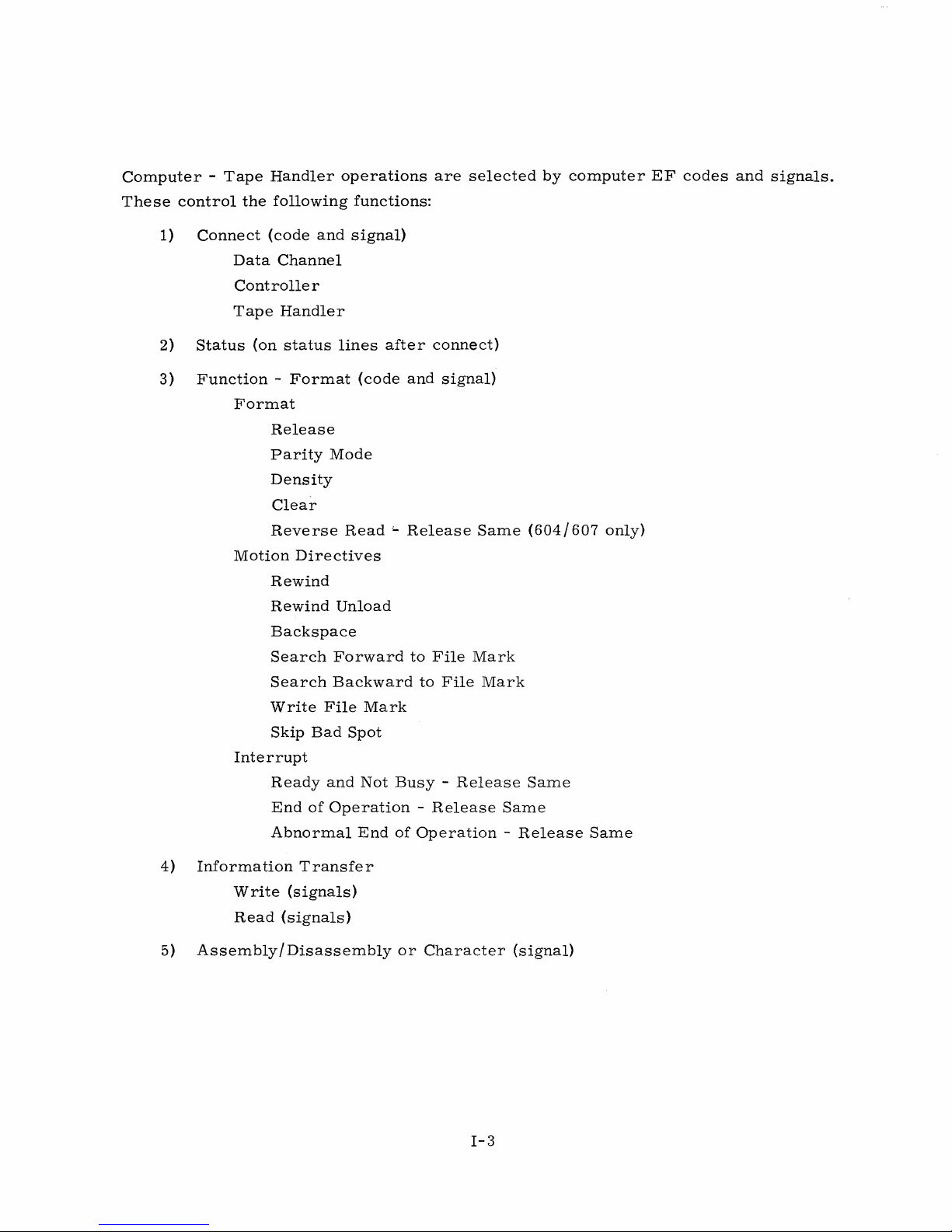
Computer -Tape
These
control
1)
the
Connect
Data
Controller
Tape
2)
Status
3)
Function -Format
Format
Motion
Interrupt
Handler
following
(code
Channel
Handler
(on
status
Release
Parity
Density
Clear
Reverse
Directives
Rewind
Rewind
Backspace
Search
Search
Write
Skip
Ready
End
Abnormal
operations
are
functions:
and
signal)
lines
after
(code
connect)
and
Mode
Read '-Release
Unload
Forward
Backward
File
Bad
Spot
and
Not
of
Operation -Release
End
to
File
to
Mark
Busy -Release
of
Operation -Release
selected
signal)
Same
Mark
File
Mark
(604/607
Same
Same
by
computer
only)
Same
EF
codes
and
signals.
4)
Information
Write
Read
5)
Assembly/Disassembly
Transfer
(signals)
(signals)
or
Character
(signal)
1-3

SECTION
2.
DESCRIPTION
The
3228/29
rations.
of
an
actual
60090100).
CLEAR
Prior
five
to
possible
1)
2)
controllers
The
installation
installation
Description
initial
use
ways
Clear
This
handler
Clear
This
Channel
instruction
connection.
(2 J,Lsec)
instruction
"connected"
channel.
of
of
clearing
in
by
of
the
(100
the
PHYSICAL
may
be
mounted
engineer
using
the
data
3228/29
FUNCTIONAL
tape
controller,
the
J,Lsec)
clears
clears
all
the
sense
DESCRIPTION
in a number
can
determine
from
control
controller:
activity
tape
handler
that
Status
of
the
accurate
the
3200
Site
panel
is
DESCRIPTION
the
system
in
the
should
data
connection
signals
are
different
Preparation
in
Section
be
channel
but
still
available
cabinets
physical
3,
Operation.
cleared.
and
clears
the
controller
and
description
Manual
There
the
for
the
configu-
(Pub.
are
tape
remains
data
No.
3)
The
latter
controller
4)
5)
Both
Master
Release
This
instruction
relevant
two
Function
is
connected
Power
When
power
Logic
the
data
External
This
clears
No
Status
Clear
clears
only
in a 3228/3229 -used
instructions
to a tape
On
MC
is
in
the
applied
controller
to
is
channel.
MC
all
tape
handlers
signals
operations
are
available
place
the
(Clear
handler.
the
3228/29,
also
connected
the
connection
for
compatibility).
and
cleared,
to
the
data
3228/29
I-4
for a connected
Release)
all
tape
handlers
and
no
Status
and
clears
channel
in
binary
can
only
the
after
format.
be
connected
signals
logic
executing
tape
used
are
in
handler
after
are
available
the
controller.
this
(not
the
cleared.
to
operation.

CONNECT
The
computer
A
manual
except
must
tion.
of
used.
the
the
match
Bits
tape
If
processor
in
the
Connect
STATUS
After
status
the
of
sends a 12-
Equipment
ones
having
the
switch
0, 1,
handlers
none
of
via
data
code,
desired
the
handler
Selection
the
setting
and 2 may
the
3228/29
the
controllers
channels
an
Internal
tape
handler
before
bit
Connect
switch
correct
on
have
have
has
attempting
code
on
bit
combinations
the
3228/29
octal
values
will
communicate.
or
any
the
proper
Reject
been
over
the
tape
or
of
other
equipments
switch
is
generated
connected,
any
further
the
data
controller
in
the
processor
0 - 7.
Bits
setting,
by
it
is
operations.
channel
bits
9,
These
3,
physically
the
usually
to
locks
10,
out
and
will
bits
determine
4,
5, 6, 7,
or a parity
computer.
necessary
the
t~pe
all
Connect
11.
not
make
and 8 are
connected
error
controller.
These
the
connec-
with
to
the
occurs
to
check
codes
bits
which
not
the
Ready
A
has
the
The
control
Ready
been
tape
Ready
(XXXI)
handler
panel.
Read/Write
This
signal
1)
2)
3)
This
signal
1)
indicator
applied
signal
Control
is
present:
If
the
tape
During
etc.
and
).
Whenever
struction.
will
not
The
tape
on
and
the
is
controlled
is
not
(and/
handler
for 5 ms
the
be
handler
the
tape
present
data
present
tape
or)
is
channel
is
handler
handler
by
the
when
Busy
Ready.
after
if:
not
Ready.
lights
is
in
tape
the
(XXX2)
any
operation
begins
when
Automatic
controller.
tape
handler
executing
it
is
in a Ready
mode.
is
requiring
or
is
condition,
When
manually
tape
in
operated
motion
Automatic
(Read,
executing a Read/Write
i.
e. J power
mode,
from
\Vrite,
its
in-
2)
The
channel
a.
Lost
b.
Interrupt
ation
begins
Data
and
has
On
the
executing
occurred
Abnormal
Interrupt
or
is
executing a Read/Write
in a previous
End
of
Operation
signal
is
1-5
still
operation.
has
present.
occurred
instruction,
in a previous
and/
oper-
or:

Write
This
signal
from
File
This
Mark.
drops
End
Load
This
motion
End
This
tape
Enable
signal
is
the
Mark
signal
It
when:
of
File
Point
signal
begins.
of
Tape
signal
has
(XXX4)
is
absent,
tape.
(XX1X)
is
is
also
(1)
Mark
(XX2X)
is
(XX4X)
is
been
present
present
it
is
only
impossible
when
present
reading/writing
Forward,
present
present
rewound
when
when
past
when
the
to
the
tape
immediately
begins
or
Search
the
tape
the
End
the
End
file
protection
write
handler
after
on a new
End
is
at
of
Tape
of
Tape
on
tape,
has
writing
of
File
Load.
marker
marker.
ring
although
searched
an
record,
Mark
Point.
is
End
Backward
The
is
detected.
on
the
information
for
and
of
File
or
(2) a
signal
tape
reel.
may
located
Mark.
Backspace,
operation
drops
The
when
signal
an
This
is
When
be
read
End
signal
Search
initiated.
tape
drops
this
of
when
File
Density
See
table 1-2
Density
See
table 1-2
Lost
Data
This
signal
ler
is
When
Write
or
Connect
The
Lost
the
tape
is
absent.
(X1XX)
(X2XX)
(X4XX)
appears
ready
the
to
Lost
operations
code.
Data
controller
accept
Data
are
signal
during a Write
information
signal
appears
impossible
also
appears
has
data
ready
operation
but
the
Data
during a Write
until
the
Lost
during a Read
for
output,
(Write
signal
Data
operation
but
the
signal
from
operation,
signal
Data
present)
the
data
tape
is
cleared
(Read
signal
if
channel
motion
with a new
signal
from
the
tape
stops.
present)
the
is
data
control-
absent.
Further
Function
when
channel
1-6

If
the
of
the
cleared
1-2
will
The
Lost
via
a 3681
to
continue.
End
of
This
Lost
Data
record.
with a new
clear
Data
adapter.
Operation
signal
indicates
signal
Further
the
Lost
signal
(lXXX)
appears
Read
Function
Data
is
meaningless
However,
that
an
during a Read
operations
or
Connect
signal.
)
when
this
signal
operation
are
impossible
code.
the
must
is
completely
operation,
(Any
legal
tape
controller
be
cleared
finished.
reading
until
Function
if
Read/Write
the
is
attached
continues
Lost
Data
code
listed
until
the
signal
in
table
to
a
160/160-A
operations
end
is
are
Parity
This
signal
This
signal
External
Parity
mode.
SELECT
The
following
tion,
i.
and 5 of
motion,
The
proper
If
an
error
Parity
an
Internal
Error
(2XXX)
indicates
drops
Master
Error
signal
FUNCTION
information
e.,
the
the
Function
and
an
tape
occurs
Error
signal
Reject
that a parity
when
Clear
also
CODES
lower
12
code
octal 2 in
handler
in
the
appears
after
reading
begins
or a Power
appears
refers
bits
which
indicates
bits
3, 4,
must
be
Function
on a transmission
100
usec.
error
has
on a new
On
Master
when
to
an
the
Function
specify
End
the
format,
and 5 indicates
connected
code
(assuming
occurred
record.
Clear
of
codes
operation.
an
octal 1 in
during a Read/Write
A
causes
File
Mark
used
An
bits
Interrupt.
before a Function
the
proper
parity
error
Clear
this
is
with
Channel
signal
sritten
the
or
Function
octal 0 or 4 in
3, 4,
and 5 indicates
instruction
unit
is
connected),
line
and
the
operation.
instruction,
to
drop.
read
bits
can
computer
The
in
Binary
instruc-
3, 4,
be
issued.
a
tape
issues
Once a function
channel,
some
the
it
operation
operation
(Backspace,
is
possible
on
on
the
the
second
to
connect
second
Rewind,
tape
handler
etc.)
another
handler,
terminates.
is
tape
and
I-7
initiated
handler
reconnect
un a tape
on
the
same
the
first
handler
channel,
tape
on a given
perform
handler
when
Rev.
C

FORMAT
Release
A
Release
(0000)
code
clears
the
existing
unit
connection
for a tape
handler.
Binary
A
0001
(0001)
code
generator
a
total
of
the
longitudinal
operations,
a
status
Coded
A
0002
(0002)
code
notation.
(vertical)
Write
556
200
A
operations
BPI
BPI
0003/0004
556/200
allows
makes
seven
a
constant
line
if
allows
A
parity
direction
Density
Density
code
density.
all
the
separate
number
a
vertical
all
generator
on
are
(0003)
(0004)
permits
information
total
number
tracks
of
bits
transverse
parity
information
the
seven
performed
all
to
be
of 1 bits
on
tape.
in
each
parity
error
to
be
makes
the
tracks
in
the
information
written
The
of
the
check
is
detected.
written
total
on
same
to
odd
seven
number
tape.
manner
be
or
in
the
End
is
made.
or
Constant
written
read
transverse
of
Record
tracks
read
of 1 bits
as
onto
in
A
in
in
binary
check
even.
parity
binary
even
parity
binary
or
notation.
(vertical)
character
During
error
coded
in
checks
format.
read
from
Read
is
decimal
the
transverse
during
A
parity
direction
makes
or
indicated
Read/
the
tape
on
Write
on
(BCD)
at
Clear
A
0005
code
when
800
BPI
A
0006
density.
Set
Reverse
This
code
607
Tape
Rev.
C
(0005)
code
the
Density
code
(On
is
Handlers
clears
all
channel
existing
has
(0006)
permits
604/607
Read
used
all
information
Tape
(0041)
for a Revers e Read
only.
)
tape
completed
Handlers
handler
all
operations
to
be
only.
operation.
connections.
written
)
1-8
on
one
or
read
(See
Revers e Read
It
is
or
onto
desirable
more
or
from
tape
handlers.
the
section.)
to
issue
tape
this
at
(On
800
604/

Clear
This
All
Reverse
code
of
the
Read/Write
clears
Format
control
Read
the
codes
(0040)
condition
(0000-0006,
is
busy.
established
0041,
by
0040)
the
0041
result
Format
in a Reject
code.
if
attempted
when
the
Rewind
A
0010
code
further
appears
Rewind
A 0011
code
further
Backspace
A
0012
code
beginning
length
Search
Search
A
File
marks
behind
End
End
0013/0014
Mark
are
(0010)
rewinds
Rewind
instructions
on a status
Unload
(0011)
rewinds
operations
(0012)
backspaces
of
the
the
of
File
of
File
code
signal
detected,
line
on
tape,
Load
Mark
Mark
searches
appears
tape
when
tape
this
tape
this
Point.
tape
at
high
speed
will
initiate
the
operation
at
high
speed
tape
are
one
record
code
will
Forward
(0013)
Backward
forward/reverse
on a status
motion
continues
(225-400
an
until
locked
length.
backspace
(0014)
line
imm
is
all
out
until
when
until
inches/second)
ediate
Reply.
complete.
the
tape
until
the
If
the
tape
from
an
End
the
operation
tape
is
is
on
tape
has
Load
Point
Load
of
File
is
completely
to
the
A
Load
the
supply
been
occurs
Point
:Mark
complete.
off
Load
Point
reel.
reloaded
than
to
one
is
detected.
If
the
supply
Point.
signal
All
manually.
at
record
no
Any
the
A
file
reel.
Write
A
and
Skip
A
End
0015
BCD
Bad
0016
of
End
of
code
writes
format.
Spot
code
moves
Operation
File
(0016)
Mark
178
Writing
and
is
selected,
(0015)
as
erases
complete.
Codes
the
0010-0016
Read/Write
an
End
an
End
tape 6 inches
Interrupt
control
of
File
of
File
result
Mark
Mark
in a forward
will
occur
NOTE
in a Reject
is
busy.
I-9
(even
does
when
transverse
not
change
direction.
the
if
attempted
Skip
parity)
the
Bad
when
in
current
If
Interrupt
Spot
both
binary
format.
operation
On
is
Rev.
C

INTERRUPT
All
desired
occur
line
switch
interrupt
This
during
the
is
signal
Interrupt
set
line
Clear.
Interrupt
any
other
signal
to
5,
5.
Any
is
also
instructions
operation.
is
any
Interrupts
new
cleared
must
transmitted
coming
Interrupt
by
releasing
come
The
Equipment
on.
from
instruction
all
before a Read
Selection
For
example}
the
controller
clears
three
possible
the
or
Write
switch
if
the
Equipment
will
existing
Interrupts
operation,
determines
be
transmitted
Interrupt
or
doing a Master
but
which
Selection
on
signal.
can
Interrupt
Release
The
0020
tape
handler
unit
is
and
Not
Interrupt
Release
A
0022
after:
1)
2)
3)
4)
Release
on
Interrupt
code
in
Automatic
Busy
on
Interrupt
code
A
File
operation
Load
A
Skip
Interrupt
Ready
and
ob.
Not
Ready
allows a tape
is
in a Ready
mode,
code
0021
End
of
Operation
on
End
allows a tape
Mark
Point
Bad
on
has
has
Spot
End
Busy
and
unit
and
and
clears
(0022)
of
Operation
handler
been
been
detected
operation
of
Operation
(0020)
Not
to
Not
Busy
all
tape
this
to
located
Busy
(0021)
send
an
Interrupt
condition,
motion
condition.
(0023)
send
an
Interrupt
in a Search
during a Rewind
has
been
completed.
code
0023
has
clears
signal
i.
e.,
ceased.
signal
File
Mark
operation,
when
this
out
on
the
power
Release
out
on
Forward
or
condition.
channel
is
applied,
Interrupt
the
channel
or
when
the
on
Backward
this
Ready
Interrupt
Release
A
0024
normal
Point,
Ready.
ditions
Rev.
on
Interrupt
code
operation
Transverse
In
is
C
Abnormal
on
allows a tape
occurs.
all
but
the
encountered
End
Abnormal
Parity
last
and
unit
Error,
case,
an
of
Operation
to
The
End
End
of
send
abnormal
Lost
the
Interrupt
of
Record
(0024)
Operation
an
Interrupt
operations
Data,
and
check
1-10
(0025)
Connected
occurs
signal
are:
when
character
out
on a channel
End
of
Tape
one
or
is
written
Tape,
Handler
more
after
File
Becoming
of
these
or
read
an
Mark,
con-
by
ab-
Load
Not
the

tape
unit.
Interrupt
condition
Connected
ation
or
A
new
Read/Write
the
methods
Interrupt
The
processor
Activity
activity
(in
the
processor
The
processor
Interrupt
by a new
In
the
occurs
(e.
g.,
Tape
Handler
(2)
when a 0000
mentioned
on
Abnormal
will
instruction
and
store
will
signal
Write
is
instruction.
case
of
Interrupt
immediately
if
someone
Becoming
Function
operation
previously
End
enter
the
(in
the
present
an
Interrupt
enter
an
cleared
when
were
to
instruction
cannot
of
Operation
Interrupt
processor
word
routine),
Interrupt
(in
the
processor
on
Connected
the
handler
turn
Not
Ready
start
in
this
routine
Interrupt
count,
reading
routine
off
the
until
chapter
code
etc.
Tape
goes
power
will
not
(Release
the
Interrupt
under
0025
clears
and
process
routine)
When
may
be
and
process
Interrupt
Handler
Becoming
from a Ready
on
the
tape
occur:
(1)
Connected
signal
the
Interrupt
this
condition.
the
Interrupt.
will
terminate
the
Interrupt
initiated
routine),
by a new
the
Interrupt.
writing
Not
Ready,
to a Not
unit).
Ready
Interrupt
during a Connect
Unit)
is
cleared
section.
signal
is
being
data
Read
may
executed.
by
Release
A
Stop
channel
is
cleared
instruction.
When
the
be
initiated
on
oper-
one
of
Channel
INFORMATION
Write
Mter
check
present,
write
not
by
the
status
on
present,
the
Ready
tape
for a Write
the
protective
the
tape
the
signal,
Read
In a Read
necting,
It
is
possible
During
ically.
not
necessary
Read
He
operation,
checking
when
and
may
TRANSFER
handler
data
only
has
when
channel
the
the
status,
to
check
the
protective
Write
also
program
been
connected
Enable
ring
is
probably
this
(bit 2 in
condition
hangs
Write
order
and
operation
of
choosing
for a Write
ring
operations,
one
up.)
events
is
not
the
or
more
and
format
the
Status
missing
has
If
may
is
the
proper
Enable,
present
been
the
Write
begin.
similar
on
from
since
programmer
Interrupts
chosen,
Reply
the
corrected.
Enable
to
the
format,
Read
the
tape
may
to
let
the
code).
tape
is
Write
the
Read
operations
reel.
choose
the
programmer
If
this
reel.
(If
It
the
present,
operation.
operation
to
check
computer
signal
is
possible
Write
Enable
accompanied
After
from
the
status
know
should
is
not
to
con-
begins.
tape
period-
when
is
are
1-11
Rev.
C

the
present
operation
is
complete.
Reverse
The
read
word
to
the
made
To
all
0041
Read
from
Read
322X
can
from
tape
is
read
word
in
the
initiate a Reverse
tape
motion
(Reverse).
operation
the
322X
Transverse
one
exception:
check
is
made
frames.
(On
604/607
read
information
and
assembled
in a reverse
which
final
was
order
has
stopped), a 322X
When
will
begin.
to
indicate
and
longitudinal
if
the
on
that
Tape
direction
initially
of
the
Read
the
operation
Read
A
that
first
frame
character.
Handlers
in a reverse
into
written
bits
during a Reverse
instruction
Reverse
the
12-bit
parity
read
Vertical
12-bit
from
on
bytes
tape
the
(assuming
controller
Assembly
bytes
checking
is a record
Only)
direction
tape
is
occurs
parity
and
sent
and
entered
from
Read
format
must
executed
signal
should
as
check
checking
from
tape.
to
the
into
storage.
operation.
has
already
first
receive
in
the
will
be
be
assembled
in a normal
character,
is
Six-bit
data
channel.
storage,
There
been
the
processor,
sent
to
in
Read
no
performed
frames
it
is
is
no
selected
Function
the
the
data
reverse
operation
vertical
on
all
are
When
identical
change
and
code
Reverse
channel
order.
with
parity
remaining
a
If
C\.
Reverse
operation
Parity
An
If
the
The
ation
DA
errors
End
of
a
Backspace
tape
will
Function
terminates.
T A
CONVERSIONS
Transmission
All
information
and 1 parity
a
Write
Rev.
operation
C
Read
will
halt
and
Record
function
"backspace"
code
Parity
transfer
bit
(odd
is
attenlpted
indefinitely.
Interrupts
signal
is
is
selected
forward.
0042
(Clear
between
parity).
and
generates
from
may
returned
Reverse)
the
The
the
Load
be
handled
to
the
during
data
controller
bit
during a Read
Point,
as
if
data
channel
the
time a Reverse
should
be
channel
checks
1-12
the
issued
and
the
operation
~hen
when
the
controller
accuracy
operation.
were a Normal
a
record
Read
the
gap
format
Reverse
uses
of
the
is
is
Read
12
parity
The
Read.
reached.
selected,
oper-
bits
of
bit
Read
data
during

Illegal
The
tape.
tape
the
128
the
BCD
tape
handler
Therefore,
handler
controller
to
all
zeroes
computer.
generates a sprocket
if a 6-bit
will
not
automatically
when
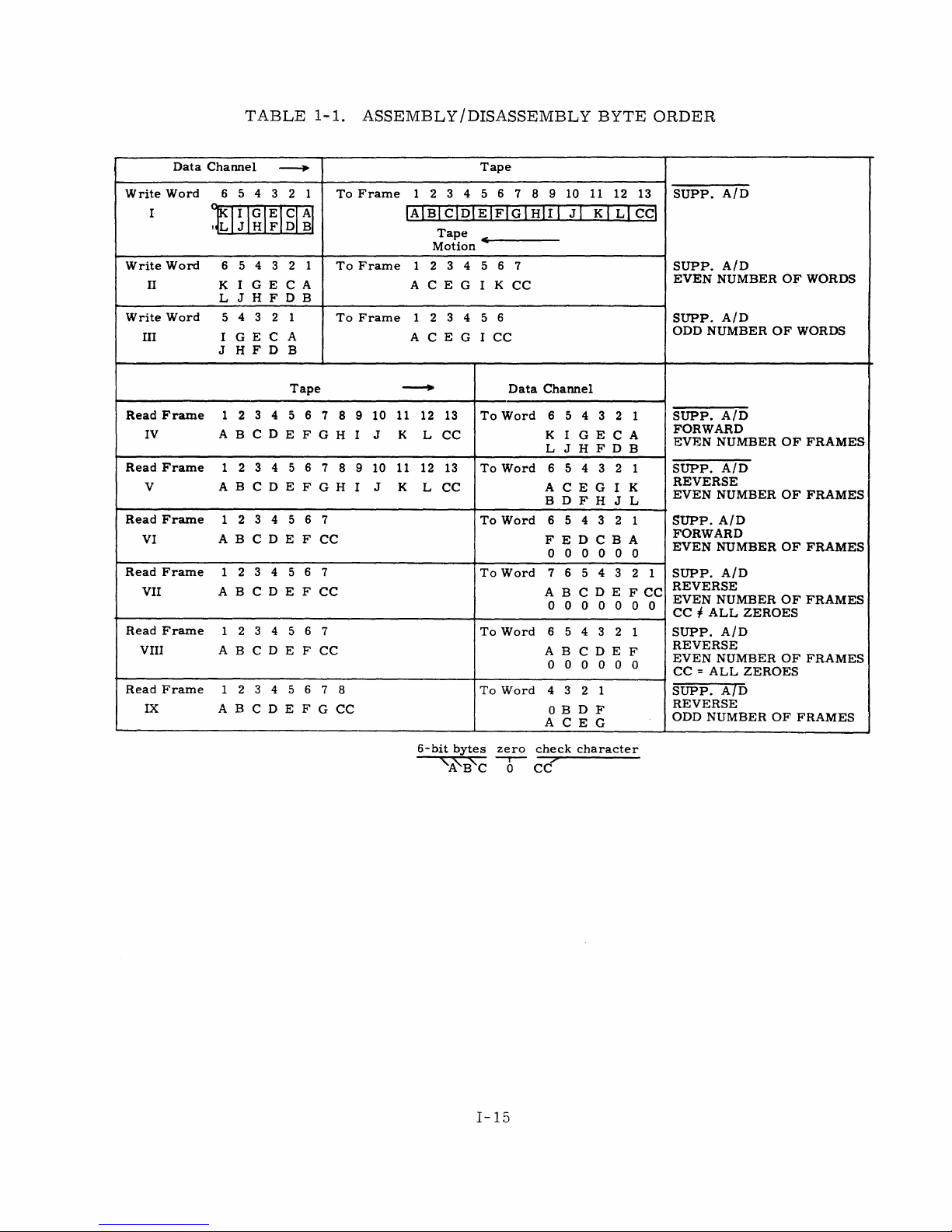
Assembly / Disassembly
Example I in
word
are
bled
to
the
table
written
data
1-1
on
tape.
channel.
data
recognize
the
converts a character
reading.
shows
the
Example
Example V shows
pulse
character
frame
This
makes
order
IV
in
shows
whenever
of
all
and
an
128
which
the
the
it
zeroes
error
of
all
BCD
an
the
two
order
assembly
senses a bit
is
written
would
zeroes
illegal
occur.
in
to
128
number
characters
in
which
data
during a Reverse
in a frame
BCD
To
prevent
when
in
in
each
on
tape
mode,
writing
relation
data
is
assem-
Read.
on
the
the
this,
and
to
channel
Suppress
If
the
operation,
Assembly/Disassembly
Suppress
bits 6 through
through 5 are
If
the
signal
bits 6 through
VII,
and
VIII).
Programlning
1)
If
data
Disassembly
is
that
may
controller
with
attempted,
through 5 of
example
Assembly/Disassembly
11
of
written
is
sent
11
of
to
the
on
the
the
Data
tape
controller
Channel
Considerations:
is
to
be
assembled
mode,
in
Suppress
be
written
zeroes.
will
the
the
Assembly/Disassembly
on
the
automatically
If
an
odd
inverted
last
IX).
the
Data
(table
from a tape
assembly
tape.
number
assembly
Data
Channel
signal
Channel
1-1,
is
sent
word
examples
during a Read
input
word
are
that
difficulties
If
this
occurs,
fill
in
bits 6 through
of
frames
will
be
word
will
to
the
are
II
operation
packed
was
recorded
may
be
mode,
and
are
written,
one
frame
be
filled
controller
discarded
and
II!).
(forward
with
zeroes
encountered.
an
odd
the
tape
is
11
of
the
and a Reverse
out
of
in
with
during a Write
and
only
or
reverse),
(examples
in
Suppress
The
number
read
forward,
last
input
order
and
zeroes
bits
Assembly/
problem
of
frames
word
Read
bits
(table
0
VI,
the
is
0
1-1,
2)
If
a
Reverse
check
character
Channel
because
read
as
Read
character).
of
an
even
the
first
may
Data
is
attempted
be
If
number
Channel
read
no
to
check
of
bits
in
Suppress
the
Data
character
in
each
character
I-13
Assembly / Disassembly
Channel
exists
tape
(table
as
the
(check
channel),
1-1,
examples
last
character = zero
the
frame
last
VII
mode,
(first
frame
and
Data
will
VII!).
Rev.
the
be
C

Write
Write
II
Write
III
I
TABLE
Data
Channel
Word
65432
tl~I~I~lgl~1
Word
Word
5 4 3 2 1
6
I G E C A
K
J H F D B
L
543
I G E C
J H F D
---.
2 1
1-1.
1
A
B
ASSEMBLY/DISASSEMBLY
Tape
To
To
To
Frame
Frame
Frame
1
23456
IAIBlclDIEIFIGIHll1
Tape
Motion
234
1
CEG
A
234
1
A C E G I
~
5 6 7
I K
5 6
7 8 9 10
CC
CC
JI
BYTE
11
12
KI
LI
ORDER
13
cci
SUPP.
SUPP.
EVEN
SUPP.
ODD
AID
AID
NUMBER
AID
NUMBER
OF
OF
WORDS
WORDS
Read
Frame
IV A B C D E
Read
Frame
V
Read
Frame
VI
Read
Frame
VII A B
Read
Frame
VIII
Read
Frame
IX
1
2
1 2
ABCDEFGH
1
234
ABCDEF
1 2
1 2 3 4 5 6
AB
1
234
ABC
Tape
345
345
5 6
345
CDE
C D E F
5
D E
6 7
FGH
678
CC
6
F
CC
CC
6
F
G
8 9
I J
9 10 11 12
I
7
7
7
7
8
CC
---+
10 11 12
K
L
J K
L
6-bit
13
CC
13
CC
bytes
'-A'B'C
To
To
To
To
To
To
Data
Word
Word
Word
Word
Word
Word
zero
6
Channel
6 5 4 3 2 1
K I G E C A
L
JHFDB
654
ACEG
BDFH
6
FEDCBA
o
7 6
ABC
000
3 2 1
543
000
543
D E
0
65432
AB
CDEF
o 0 o
4 3
000
2 1
o B D F
ACEG
check
character
cc!'
I K
J L
2 1
0 0
000
2
FCC
1
SUPP.
FORWARD
EVEN
SUPP.
REVERSE
EVEN
SUPP.
FORWARD
EVEN
1
SUPP.
REVERSE
EVEN
CC I ALL
SUPP.
REVERSE
EVEN
CC = ALL
SUPP.
REVERSE
ODD
AID
NUMBER
AID
NUMBER
AID
NUMBER
AID
NUMBER
ZEROES
AID
NUMBER
ZEROES
AID
NUMBER
OF
OF
OF
OF
OF
OF
FRAMES
FRAMES
FRAMES
FRAMES
FRAMES
FRAMES
1-15

SECTION
3.
OPERATION
Read/Write
For
For
EQUIPMENT
An
Equipment
switch
the
controller
the
setting
time
the
603/604
200
bpi
556
bpi --24 fJ,sec
800
bpi --16.6
the
606/607
200
bpi --33.
556
bpi --12
800
bpi
SELECTION
Selection
designates
will
of
the
When a controller
Selection
switch
on
switch
the
tape
for
one
tape
- -
66.
6 fJ,sec
tape
3 fJ,sec
--
8.3
switch
the
controller
be
transmitted
Equipment
is
connected
is
illuminated.
handler
6-bit
frame:
handler:
fJ,sec
(604
handler:
fJ,sec
fJ,sec
(607
SWITCHES
SWITCH
Selection
lights.
only)
only)
AND
is
associated
as
equipment
on
one
switch.
to a tape
When a tape
INDICATORS
with
number
of
the
eight
handler,
handler
each
Interrupt
a
white
channel.
N.
Any
indicator
is
in
use,
The
setting
Interrupts
lines
corresponding
in
the
Equipment
coming
the
Equipment
of
this
from
to
Select
If
a
transmission
red
indicator
in
LONGITUDINAL
At
the
end
of
an
Parity
error
indicators
has
occurred.
WRITE
The
Write
The
Write
VERTICAL
A
Vertical
operation.
indicator
indicator
PARITY
Parity
This
parity
the
Controller
PARITY
operation
should
is
illuminated
remains
Error
light
is
error
occurs
involving
be
lit.
on
indicator
lit
until a new
during a Function,
Equipment
longitudinal
If
one
or
during
until
the
lights
Selection
more
Write
Write
if
a
record
I-16
parity
are
and
operation
vertical
is
begun.
switch
checking,
lit,
it
Write
parity
Read,
or
Write
operation,
lights.
none
of
the
Longitudinal
indicates a longitudinal
End
of
File
Mark
operations.
terminates.
error
occurs
during
a
parity
an

INTERRUPT
This
indicator
signal
drops.
BCD
This
indicator
tape.
(INT)
lights
lights
when
when
an
Interrupt
BCD
mode
occurs.
is
selected
This
or
light
an
End
is
of
lit
File
until
Mark
the
Interrupt
is
written
on
Rewind
Rewind
Backspace'~
Search
Unload
End
of
Forward
Release
.
Binary
Coded
Density
Density
Interrupt
Not
(556
(200
on
Busy
Releas e Inte
Ready
Interrupt
and
on
Operation
XXXI
XXX2
Ready
Read/Write
Busy
XXX4
XXIX
XX2X
XX4X
i.<
Write
End
If
a
Backspace
forward
File
Load
of
direction.
TABLE
File
BPI)
BPI)
Ready
rrupt
Not
Busy
End
Enable
Mark
Point
Tape
1-2.
Mark
and
on
of
Control
operation
FUNCTION
0020
0021
0022
STATUS
and/
or
is
executed
CODES
Release
Interrupt
Release
RESPONSE
XIXX
X2XX
X4XX
lXXX
2XXX
when
Reverse
AND
STATUS
Interrupt
Operation
of
Operation
Interrupt
End
of
Operation
Density
Density
Lost
End
Transverse
Read
on
Abnormal
Data
of
Parity
is
RESPONSES
on
End
End
on
Abnormal
(1
in
bit 6 indicates
556
BPI)
(0
in
bit 6 and
indicates
(800
BPI) 1 in
Operation
or
Longitudinal
Error
set,
tape
of
200
is
bit
BPI)
bit
moved
0023
0024
0025
7
7
in
a
1-17

PART
II.
THEORY
OF
OPERATION
The
controller
the
Data
Channel.
handler
in
Figures
Connect
(B)(Figure
2-1
code
and
+0. 2 psec -start
+ 1
psec -enable
receives
The
a
Connect
2-1).
and 2-2. A
TABLE
signal
from
Check
Connect
Set
Clear
Set
T 2
if
proper
Set
Light
SECTION
12-
bit
Connect
code,
The
sequence
timing
2-1.
the
data
code
timing
chain
Connect
Controller
Connect
Reject
FF
Connect
Controller
Controller
1.
code
AXXB,
of
events
chart
for
the
CONNECT
channel.
for
transmission
(T
1).
FF -prevent
Connect
code
if
Read/Write
code
Connect
Connect
CONNECT
accompanied
selects
followed
Connect
SEQUENCE
parity
(Page
2)
Interrupt
FF
if
for
controller.
Active
and
if
Reject
FF -permits
indicator.
by a Connect
the
controller
during a Connect
sequence
error.
during
parity
and
FF
error
controller
is
not
further
(A)
is
shown
(Page
Connect.
or
if
set.
operation.
signal
and
the
is
in
..
,
','
1)
not
proper
is
reselected.
(Page
from
tape
shown
Figure
2)
2-3.
+1
psec -enable
+ 1
p,sec -enable
Connect
*Page
code
numbers
Customer
and
Reject
signal.
Engineering
T 3
Set
T 4
If
If
Clear
signal
in
parentheses
tape
handler
conjunction
Selection
proper
signal
no
tape
Reject
Connect
drops
after
refer
Diagrams
tape
handler
handler
the
Manual
Select
FF
with
switch.
is
to
data
channel.
is
selected,
signal
to
FF -allows
data
channel
to
the
3228/3229
(Pub.
II-I
according
setting
(Page
selected,
set
data
channel.
Interrupt
receives
No.
60093700).
to
of
the
4)
set
Reply
(Page
Reject
to
Magnetic
Connect
tape
handler
FF -send
2)
FF
- + 2
perform.
either
Tape
code
in
Equipment
p,
sec
the
Reply
Controller
Reply
send
or

r:tj
1-'.
CTQ.
C
1-1
(D
~
I
I-'
1-1
1-1
n
I
~
0
::J
::J
(D
(J
r+
r:tj
r:tj
(fl
CONTROLLER
CONN
ECT
TRANSMISSION
PARITY
ERR::
~.~
PROPER
CONNECT
CODE*
~~
TI
*
EQUIPMENT
SELECT
SWITCH
XXXB
SELECT
CODE
TAPE
HANDLER
SE
LECT
SWITCH
NO
TAPE
HANDLER
SELECT
SIGNAL
RE
JECT
FF
TAPE
HANDLER
SELECT
FFS
KO-O
KO-I
CLEAR
RELEASE
AND
CON N
ECT
CODE
AXXX
PROPER
CONTROLLER
CONNECT
CODE
KI04
REPLY
KI03
KI05
REJECT
F F
CONNECT
SIGNAL
KI02~
I
KICl5~
II02
T 2
K102~
I
K104~
II03
T3
K103~
I
K104~
1104
T4

~
1-"
O"Q
C
1-1
ro
I:\.:)
I
I:\.:)
()
I-t
0
I-t
::s
I
w
::s
ro
()
ri-
O
"d
ro
1-1
P'
ri-
1-"
0
::s
CONNECT
ENTER
CONNECT
SIGNAL,
12-B IT
CONNECT
CODE,
PARITY
PARITY
SIGNAL
SET
,--
- -
INITIATE
TIMING
CHAIN
DO
TRANS.
PARITY
CHECK
SET
CONNECT
FF
(T
I)
PAR
ITY
ERROR
FF
SET
CONT.
CONNECT
FF
(T2)
LIGHT
DOES
THE
FOLLOWING
EXIST?
I.
TRANSMISSION
PARITY
ERROR
PREVENT
AB.
END
-OF-OPERATION
INT. DURING CONN.
BITS
9,10,
a II
GO
THROUGH
OCTAL
SWITCH
LIGHT X MSN
PARITY
ERROR
INDICATOR
DO
TAPE
EQUIP.
SWITCH a CODE
AGREE?
NO
CODE
AGREE
SET
SELECT
F F
(T3)
NO
CLR.CONT.
CONNECT
FF
(TI)
CLEAR
CONTROLLER
CONN.
FF(TI)
SET
REPLY
FF,
CL.CON
N.
FF
(T4)
REJEC
T
CONTROLLER
SET
REJECT
CLEAR
CONNECT
FF
(TI)
CLEAR
REPLY
FF
INDICATOR
FF,
CL.
CONN.
FF
(T4)
YES
DESIRED
TAPE
UNIT
IS
NOW
CONNECTED
AND
INVERTERS
GATE
THE
FLOW OF
INFORMATION
BETWEEN
THE
TAPE
UNIT
AND
DATA
CHANNEL
VIA
THE
MAG
NET
IC
TA
PE
CON
TROL
L E
R.
REJECT
FF
--
--------
------1
I
I
I
I
__________
--.1
* WHEN
THE
CONTROLLER
STOPS
YES
AND DOES
NOT
ISSU
EAR
EPLY
OR
REJECT,
THE
COMPUTER
ISSUES
AN
INTERNAL
REJECT
AFTER
100fLSEC.

CONNECT
CONNECT
KIOI
K103*
KI05
TI
SIGNALJROl3
TIMING
COSB
COSO
C
IIOI
CIIA
""lS I 9B
10
.-J
~
IE-
0.2
fL
S
EC
I I
~r--------------I------------~
I I
IE--
IfLSEC
I I
CHECK
~
I
PARITY
~--------------------------
IE--
IfLSEC
--']!~
....
I I I
IE;;"'--
I I I
IfL
SEC~
I
I
~
L..-
iE-
__________
o.lfLSEC
.....
_
T2*r102
T3
II03
T4
II04
CONNECT
KIIS/119
CONTROLLER
CONNECT
KilO/III
SELECT
KO-
0/0-1
REPLY
K114/115
REJECT
K112/113
REPLY
SIGNAL*
TO 13
S20B
REJECT
SIGNAL*
TOl4
S23A
FF*
G24
FF
C05
FFs
FF*
CI6
FF*
CI8A
*
*
CIIB
CI2A
CI2B
*
THESE
DEPENDENT
TIMES
FFs
SHOWN ARE
___________________________________________
I
~nL..__
_________
_
{6).
I
I
jE-=
I
tE-
2fLS
IfL
SEC
SCALE
EC
:n=:r-
~
r--------
I
RESELECT a R/W
AND
SIGNALS
ON OTHER FUNCTIONS.
ARE
OPTIMAL.
-
---
ACTIVE
ALSO
Figure
2-
3.
Connect
II-4
Timing

The
controller
the
Connect
or
Write
requests
necessary
this
manual.)
selection)
If
the
Function
(Figures
after
any
Function
receives a 12-
exchange.
operation
(C
= 2)
(Table
controller/tape
The
are
shown
code
2...,5
and 2 -6).
necessary
code
and
signal
SECTION
The
(C
= 0,
4),
2-2).
different
in
Figure
is
illegal,
If
the
processing
to
2.
bit
Function
certain
Each
handler
techniques
2-4.
the
code
delays.
drop.
FUNCTION
Function
code,
tape
selection
operation.
used
controller
is
legal, a Reply
code
XXCD,
motion
The
SELECTION
accompanied
selects
directives
is
recorded
(These
to
set
these
sends
Reply
the
or
the
by a FF
operations
FFs
data
signal
Reject
by a Func"tion
tape
format
(C
= 1),
(which
channel a Reject
is
sent
signal
which
are
to
permits
and
explained
record
the
signal
for a Read
Interrupt
controls
the
signal
data
channel
the
after
the
later
function
in
FORMAT
0000
0001
0002
0003
0004
0005
0006
0040
0041
Release
Binary
Coded
556
Density
200
Density
Clear
800
Density
Clear
Reverse
TABLE
Reverse
Read
2-2.
Read
0020
0021
0022
0023
0024
0025
FUNCTION
INTERRUPT
Ready
Release
End
Release
Abnormal
Release
CODES
TAPE
0010
0011
0012
0013
0014
0015
0016
and
of
MOTION
Not
Ready
Operation
End
of
End
Abnormal
DIRECTIVES
Rewind
Rewind
Backspace
Search
Search
Write
Skip
Busy
and
Not
Operation
of
Operation
End
Unload
Forward
Backward
File
Bad
Busy
of
Operation
Mark
Spot
II-5

FOR
MAT
OX
CODE
FUNCTION
~
~I
I
OX
X2
OX
XI
PARITY
FORMAT
J020
J021
CODED
BINARY
BACKWARD
4X
XI
~REVERSE
4X
~RELEASE
XO
READ
RR
MOTION
CODE
DI04
DI22
FUNCTION
INTERRUPT
CODE
(EVEN)
conE
(ODD)
TYPICAL
(00)
RELEASE
(03)
(04)
(05)
CLEAR
*(06)800
DIRECTIVES
(0)
REWIND JOOO
(II
)
REWIND
(12)
BACKSPACE
(13)
SEARCH
(14)
2X
2X
OF:
556
200
TYPICA L OF:
SEARCH
JOI8/JOI9
DENSITY
DENSITY
J026/J027
SELECT
UNLOAD
FORWARD
BACK
J022/J023*
J024/J025*
SETS
BOTH
WRITE
/JOOI
J002/J003
J004 / J005
WARD
SET
RELEASE
J006/
J008 / J009
J023
AND
CODE
DI04
DI22
ENABLE
FUNCTION
J007
FUNCTION~
J025
I
:j
_T...;,Y.,;..P....;.I..;...C_A,.:;:L_O.:....F_;
(J
5)
WRITE
(16)
SKIP
II
CL
CONTROLLER
CONNECTED
SIGNAL
--;7
FILE
BAD
EARED
______
MARK
SPOT
I
0.2fL
JOIO /
JOI2/JOI3
TERMINATION
BY
SEC
]I
~I
I
_____
JOII
REPLY
REJECT
XMSN
JO
14/
JOI6/JOI7
OF
FF
FF
PARITY
II
__
JOl5
OPERATION
ERROR
(20/21)
(22/23)
(24/25)
TYPICAL
READY
END-0 F-OPER
J030/J031
ABNORMAL
OPERATION/RELEASE
OF;
/RELEASE
END-
ATION
OF-
J028/J029
J032/J033
Figure
/RELEASE
READ/WRITE
ACTIVE
BUSY~
READY
2-4.
Function
II-6
Select
FFs
0.2fL
SEC

~
......
(Jq
~
'"i
ro
l'\:l
I
;.n
~
~
H
::s
H
()
I
c-+
-:]
......
0
::s
::0
ro
'"0
I-'
'<
-
::0
ro
.:........
ro
()
c-+
FORMAT
REPLIES
RELEASE,
BCD/BINARY,
~
REPLY
FF
CLEAR,
OR
BACKWARD
CODE I
IILSEC
I
FUNCTION
SIGNAL
REJECT
FF
DELAYED
O.4ILSEC
REJECT
FF
DENSITY
CODE
REPLY
FF
SATISFY
REPLY
FROM
TAPE
HANDLER
FUNCTION
SIGNAL
DELAYED
0.4ILSEC
200
DENSITY
SELECT
556
DENSITY
SELECT
800
BPI
REPLY
MOTION
DIRECTIVE
REPLIES
MOTION
DIRECTI
VE
FFs
~
REPLY
FF
____
I
IIILILSSEECC
I
FUNCTION
SIGNAL
INTERRUPT
REPLY
ANY
INTERRUPT
CODE
~
REPLY
FF
2X
I
FU
NCT
ION
SIGNAL
DELAYED
OAIL
SEC
END -
OF -RECOR
D
REJ
ECT
FF
REJECT
2X
REJECT
FF
REA
DY
OR
BUSY
REJ
ECT
FF
MOTION
DIRECTI
VE
REWIND
MOTION
DIRECTIVE
FF~
LOAD
POINT
REJECT
FF
REPLY
FF
*
THIS
BLOCK
PREVENTS
A WRONG
DENSITY
SIGNAL
FROM
BEING
ISSUED WHEN
CHANGING
TO
800
BPI.
OX
4X

FUNCTION
SIGNAL
CLEAR
ENABLE
MOTION
ENABLE
MOTION
ENABLE
ENABLE
DIRECTIVE
FORMAT
DIRECTIVE
FORMAT
INTERRUPT
SET
REJECT
SET REPLY
FORMAT
FF
FF
FF
FFS
FF
FF
FF
s
S
______
s
S
I
~Il~
__________________________
CHANGE
TO
800
---------~~
_
I
MOTION
REW I
AT
REJECT
REPLY
DIRECTIVE
NO
SELECT
LOAD
POINT
INTERRUPT
SIGNAL
SIGNAL
Figure
SAME
2-
AS REPLY
6.
Function
II-
FF
8
Select
Timing

05
CODE
CLEAR
TAPE
SELECT
KO-O
HANDLER**
FFs
FUNCTION
00
CODE
FUNCTION
RELEASE
Figure
2-7.
*
** SEE FIGURE
Clear
and
T2
IS
CONNECT
Release
Ko-r
INITIATED
SIGNAL
2~2
BY
II-9

This
section
detailed
is
presented
information
SECTION
may
3.
using
be
found
FUNCTION
only
simplified
in
the
OPERATION
logic
Diagram
drawings
Manual.
(FORMAT)
and
flow
charts.
More
Format
Parity
Function
Mode
Clear
Release
Density
Reverse
02
Read
CODE
OICODE~
MC
Figure
2-8
2-12
2-16
WRITE
FILE
Flow
MARK
Chart
Figure
2-9
2-10
2-11
2-13,2-14,2-15
2-17,2-18
Diagram
BCD
BITS
ODD
CHANNEL
WR
ITE
3,
9,
12
2, 3
2, 3
3,5,7,8,11
3,
5, 11
INDICATOR
6
REGISTER
Page
READ
READ
Figure
READ
BIT 6 :"1"
BIT 6 :"0"
BITS
2-
8.
II
-10
VERTICAL
r-&-~-----,
EVEN
Parity
P051
I.---~
lVlode
READ
READ
PARITY
BIT
6:"0"
BITS
ODD
ERROR
VERTICAL
ERROR
PARITY
INDICATOR

FUNCTION
ENTER
FUNCTION
SIGNAL,
12
-BIT
FUNCTION
CODE,
PARITY
PARITY
-.,;.....;...-.------~
SIGNAL
YES
SET
REPLY FF.
LIGHT
BCD
INDI-
CATOR
ON
CONTROL.
THIS
INDICATOR
STAYS
LIT
UNTIL
BCD/BINARY
FF
IS
CLEARED.
CLEAR
REJECT
FF.
*
INTERNAL
REJECT
BY
COMPUTER
AFTER
100
fL
SEC.
YES
LIGHT
XMSN.
PARITY ERROR
INDICATOR.
CLEAR
REPLY F
F.
YES
SEND
XMSN.
PARITY
ERROR
SIGNAL
TO
DATA
CHANNEL.
SET
PARITY
FORMAT
FF
(CODE
=
0002)
OR
CLEAR
PARITY
FORMAT
FF
(CODE =
0001)
SET
REJECT
FF.

f-rj
1-"
CfQ
~
'"i
([)
N
I
I-'
?
f-I
n
f-I
I
I--'
I-'
([)
N
PJ
'"i
0
'U
([)
'"i
PJ
r+
1-'.
0
::s
FUNCTION
ENTER
FUNCTION
SIGN
AL,
12 -BIT
FUNCTION
CODE,
PARITY
PARITY
----~
SIGNAL
NO
YES
*
INTERNAL
REJECT
BY
COMPUTER
AFTER
100
fLSEC.
SET
CLEAR
FF.
SET
REPLY
FF.
WHEN
THE
GLEAR
FF
SETS,
THE
SELECT
FFS
CLEAR.
THIS
CLEARS
THE
EXISTING
CONNECT
IOU
FOR T HE
TAPE
UNIT.
CLEAR
REJECT
FF.
LIGHT
XMSN.
PARITY
ERROR
INDICATOR.
CLEAR REPLY,
CLEAR
FFS.
YES
SET
SEND
XMSN.
PARITY ERROR
SIGNAL
TO
DATA
CHANNEL.
TRANSLATE
fUNCTION
CODE.
REJECT
FF.
A

~
1-'.
crq
s::
'1
ro
~
I
f-1
f-1
I-i
~
I-i
ro
I
t-J
f-1
ro
W
p:J
Ul
ro
0
'"d
ro
'1
p:J
<+
1-"
0
::s
FUNCTION
ENTER
FUNCTION
SIGNAL,
12
- BIT
FUNCTION
CODE,
PARITY
PARITY
SIGNAL
NO
YES
LIGHT XMSN.
PARITY
ERROR
INDICATOR.
* INTERNAL REJECT
BY
COMPUTER
AFTER
100
f'
SEC.
WHEN
THE
RELEASE
FF
SETS
THE
SELECT
FFS
CLEAR.
THIS'
CLEARS
THE
EXISTING
CON-
NECTION
FOR
THE
TAPE
UNIT.
CLEAR
REJECT
FF.
SET
REPLY
FF.
YES
SEND XMSN.
PARITY
ERROR
SIGNAL
TO
DATA
CHANNEL.
TRANSLATE
FUNCTION
CODE.
SET
REJECT
FF.
NO
CLEAR
RELEASE
CONNECTED
UNIT
FF.
CLEAR
REPLY
FF.
SET
RELEASE
FF

(SELECT
800
BPIl06
CODE
(SELECT
556
BPI)
03
CODE
FUNCTION
~
......
aq
~
t-i
(1)
(SELECT
800
BPI)
06
CODE
tv
I
........
I--'
........
~
(SELECT
200
BPI)
04
CODE
I
I--'
t-J:::>.
tJ
(1)
FUNCTION
::s
00
......
c-+
<:..<
556
J022
J023
J025
TAPE
SELECT
r
TO
TAPE
HANDLER
~
TO TAPE HA
NDLER
TAPE
SELECT
~:OO
556
BPI}
800
BPI
FROM TAPE
HANDLER

fTj
1-'-
O"Q
C
t-S
(!)
[\J
I
I-'
W
H
[\J
H
0
I
0
I-'
CJl
td
~
H
0
'"0
(!)
t-S
PJ
M-
1-'-
0
~
FUNCTION
PARITY
ENTER
FUNCTION
SIGNAL,
12 -BIT
FUNCTION
CODE,
PARITY
SIGNAL
* INTERNAL REJECT BY COMPUTE
RAFTER
100
II-
SEC.
~-
..... SEE FLOW CHARTS FOR
0003,
0006
CODES.
CLEAR
REPLY
FF.
CLEAR
DENSITY
200
BPI
FF.
YES
SET DENSITY
200
BPI
FF.
DROP
200
BPI
SIGNAL
TO
TAPE
UNIT.
CLEAR
REJECT
FF.
SEND
200
BPI
SIGNAL
TO
TAPE
UNIT.
LIGHT XMSN.
PARITY
ERROR
INDICATOR.
YES
NO
NO
SET
SEND
XMSN.
PARITY
ERROR
SIGNAL
TO
DATA
CHANNEL.
TRANSLATE
FUNCTION
CODE.
A
REJECT
FF.
C
SET
REPLY
FF.
A
"0"
IN
BIT POSITION 6
ON
A STATUS
LINE
AND
A
"0"
IN
BIT POSITION 7
ON
A STATUS LINE INDICATES
200
BPJ:
DENSITY
IS
SELECTED. THESE SIGNALS
REMAIN UNTIL
THE DENSITY IS CHANGED.

I-rj
f-'.
(J'Q
~
f-"'J
ro
tv
I
I---'
*'"
1-1
CJl
1-1
CJl
I
OJ
I---'
OJ
IJj
'lj
1-1
0
'\j
ro
.f-"'J
PJ
rt-
f-'.
0
~
ENTER
FUNCTION
s~
FUNCTION
SIGNAL,
12-81T
FUNCTION
CODE,
PARITY
PAR
ITY
SIGNAL
* INTERNAL REJECT
BY
COMPUTER AFTER 100
p.SEC.
r---~
SEE
FLOW CHARTS
FOR
00041,0006
CODES.
CLEAR
REPLY
FF.
CLEAR
DENSITY
~~6
BPI.
FF.
SET DENSITY
~~6
BPI
FF.
DROP
~!56
BPI
SIGNAL'TO
TAPE
UNIT.
CLEAR
REJECT
FF.
SEND
~~6
BPI
SIGNAL
TO
TAPE
UNIT.
LIGHT XMSN.
PARITY
ERROR
INDICATOR.
YES
SEND
XMSN.
PARITY
ERROR
SIGNAL
TO
DATA
CHANNEL.
TRANSLATE
FUNCTION
A
CODE.
SET
REJECT
FF.
SET
REPLY
FF.
5~6
BPI
SIGNAL
("I"
IN
BIT POSITION
6)
IS
AVAILABLE
ON
A STATUS LINE UNTIL A
DIFFERENT DENSITY
IS
CHOSEN.

I-:rj
1-'.
(Jq
~
I-i
CD
l'..J
I
I--'
~
I-i
CO
I-i
0
I
0
I--'
--l
tJj
1::J
I-i
~
CD
I-i
P'
c-+
1-'.
0
;:s
FUNCTION
ENTER
FUNCTION
SIGNAL,
12-
BIT
FUNCTION
CODE,
-.:....P..;,.A:....;,R..;,.I;..,.;T;..,.;Y:...-:.ot
PAR
IT
Y
SIGNAL
* INTERNAL REJECT BY COMPUTER
AFTER
100
f'SEC.
SEE FLOW CHARTS
FOR
0003,0004
CODES.
CLEAR
REPLY
FF.
CLEAR DENSITY
SET DENSITY
M6
BP:I,DENSITY
200
BPX
FFS.
SEND
200
BPI:,
~~
BPI
SIGNALS
~--JIIf
TO
TAPE
UNIT.
200
BPX,
DENSITyl--~
~~6
BPI:
FFS.
DROP
200
BPI,
~~6
BPI
SIGNALS
TO
TAPE
UNIT.
NO
CLEAR
REJECT
FF.
LIGHT
XMSN.
PARITY
ERROR
INDICATOR.
YES
NO
S~T
SEND
XMSN.
PARITY
ERROR
SIGNAL
TO
DATA
~HANNEL.
TRANSLATE
FUNCTION
CODE.
REJECT
FF.
SET
REPLY
FF.
A
A
"I"
IN
BIT
POSITION 7
ON
A STATUS
LINE INDICATES
800
BPX DENSITY IS
SELECTED. THIS SIGNAL
IS
PRESENT
UNTIL
THE DENSITY
IS
CHANGED.

':rj
1-'.
TO
ASSEMBLY/DISASSEMBLY
()"Q
~
CONTROL
I-oj
(D
tv
SEARCH
FORWARD
READ
FF
I
i-'
m
WRITE
TAPE
SELECT
BACKWARD
~
r
REVERSE
I-i
PJ
41
CODE
I-i
I
"d
i-'
ro
co
~
0
40
CODE
rl
1-"
TO
TAPE
0
::::J
READ
MOTION
FF
TA
PE
SELECT
w.
1-"
MC
()"Q
::::J
PJ
WRITE
MOTION
FF
r
FORWARD
I-'
Ul
READ
FF

I-:rj
......
(Tq
~
'i
(1)
tv
I
I-'
--J
I-i
::0
I-i
(1)
I
<:
I-'
(1)
CD
'i
rn
(1)
0
'"'d
(1)
'i
P'
c-+
......
0
::l
FUNCTION
ENTER
FUNCTION
SIGNAL,
12
-8
IT
FUNCTION
CODE,
NO
PARITY
PARITY
------3toI
SIGNAL
A
WHEN
THE
BACKWARD
FF
SETS,
CONDITIONS IN
THE
CONTROL
ARE
ESTABLISHED
SUCH
THAT:
I)
READ AND REVERSE SIGNALS
ARE
SENT
TO
THE
TAPE UNIT
WHEN
THE
READ
OPERATIC
...
COMMENCES, AND
2)A
REVERSE
ASSEMBLY
SIGNAL IS
SENT
TO
THE
DATA
CHANNEL.
*
INTERNAL
REJECT BY COMPUTER
AFTER
100fLSEC.
CLEAR
REJECT
FF.
YES
SET
LIGHT
XMSN.
PARITY ERROR
INDICATOR.
REPLY
FF.
YES
SEND
XMSN.
PARITY ERROR
SIGNAL TO
DATA
CHANNEL.
SET
TRANSLATE
FUNCTION
CODE.
REJECT
FF.
CLEAR
REPLY
FF.
SET BACKWARD
FF.
(THIS
FF
IS ONLY
CLEARED BY A
MC
OR A 0040
FUNCTION
CODE.)
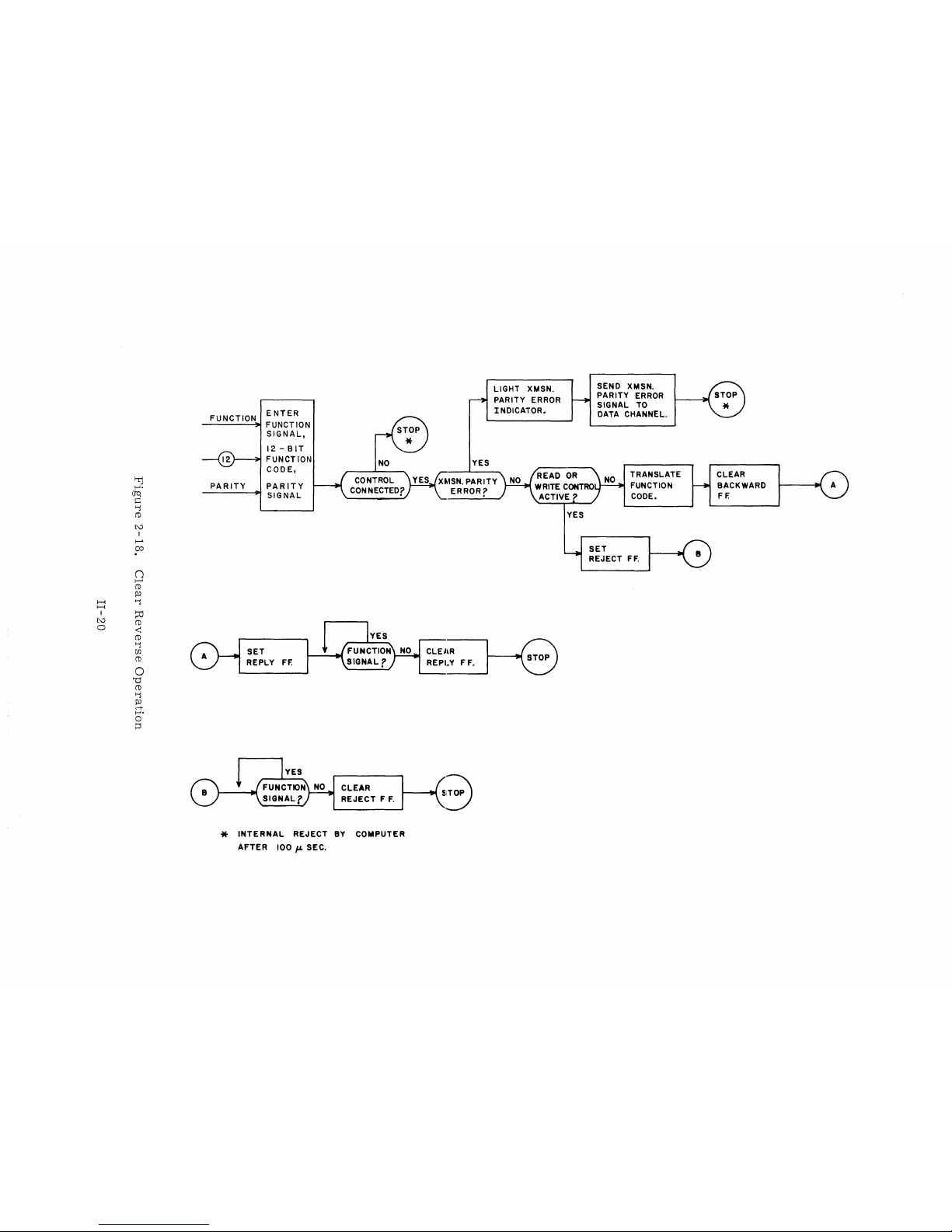
'Ij
1-"
(JQ
C
'"""i
CD
tv
I
I--'
;;0
0
t--'
CD
pJ
I-i
'"""i
I-i
I
~
tv
CD
a
-<
CD
~"l
(f)
CD
0
'd
CD
'"""i
pJ
rt
1-"
0
~
FUNCTION
ENTER
FUNCTION
SIGNAL,
12 -
BIT
FUNCTION
CODE,
_P_A_R_I
T_Y_..t
PAR
IT
Y
SIGNAL
SET
REPLY
FF.
NO
CLEAR
REJECT F F.
*
INTERNAL
REJECT
BY
COMPUTER
AFTER
100,.,.
SEC.
YES
LIGHT XMSN.
PARITY ERROR
INDICATOR.
CLEJ\R
~
~R_E_P_I
___
Y_F
__
F'
__
f
....
~
YES
SEND XMSN.
PARITY
ERROR
SIGNAL
TO
DATA CHANNEL.
TRANSLATE
FUNCTION
CODE.
SET
REJECT
FF.
CLEAR
BACKWARD
FF.
The
purpose
the
Tape
through
nization
Controller
of
the
signal
command
as
WTl,
names
imply.
of
Handler
certain
are
controlled
and
exchange
timing
RTl,
the
or
registers
the
charts.
etc.
)
SECTION
Controller
Data
Channel.
in
by
Data
Channel
and
(For
These
is
the
timing
the
timing
times
4.
INFORMATION
to
modify
The
Controller.
elements
and
the
elements
simplicity,
are
not
and
synchronize
data
modification
Internal
activated
Controller
is
this
section
always
TRANSFER
register
by
exchange
and
the
shown
later
refers
completely
data
as
is
performed
transfers
of
Tape
Handler.
in
this
to
certain
incremental
it
passes
signals
section
by
passing
and
between
The
timing
as
through
synchro-
action
in
the
elements
their
to
the'
R
to
0
This
transfer
sion
parity.
the
transmitted
Data
signal
accept
o
This
two
(DK)
this
of
B1
This
(Page
bit
2-21
if
B042.
the
information
to
Bl
transfer
6-bit
shown
transfer
disassembly.
to
B2
automatic
9).
4,
bit 5 is
converts
the
Negate
The 0 to
Negate
REGISTER
accepts
A
new
parity
from
the
performs
characters.
in
Figure
discards
transfer
The
BCD
complemented
"31"
BCD
12
BCD
signal
TRANSFERS
the
output
parity
Data
(page
bit
bit
(page
Channel
8).
the
The
2-20.
bits 6 through
performs
conversion
to
"71".
Conversion
conversion
is
not
DURING
word
is
1).
disassembly
disassembly
from
generated
The
if
the
transfer
Tape
function,
order
During a Suppress
11
of
the
the
BCD
changes
internal
(bit 4 remains
If
the
Controller
signal
occurs
present,
is
present,
if
the
and a frame
the
for
WRITE
Data
the
12
is
Handler
(Figure
Channel
bits
gated
and
converting
is
controlled
Assembly/Disassembly
output
conversion
unchanged).
is
Controller
word.
BCD
to
selected
BCD
conversion
and
external
The
is
contains
and
of
data
by
the
the
Controller
the
by
the
Table
the
O-to-12
example
to
write
selected
all
zeroes
2-19)
checks
and
the
compared
R-to-0 FF
are
12-bit
output
disassembly
mode
1-1
shows
conversion
BCD;
if
a 1
shown
in
Binary
is
blocked
to
write
(Figure 2-22).
transmis-
with
set
by
ready
word
counter
operation,
examples
appears
in
Figure
format
by
inverter
in
BCD.
the
to
into
in
or
II-21

t-rj
f-'.
crq
~
~
(1)
~
I
~
~
I-t
I-t
tj
I
~
p:J
~
ri-
p:J
t-3
~
p:J
~
r.n
f--+)
(1)
~
DATA
CHANNEL
@
@
T
L
@
-
CHECK
TRANSMISSION
PARITY
H
GENERATE
TRANSMISSION
PARITY
BIT
BCD
PARITY
CONVERSION
GENERATE
CHECK
CHARACTER
~
CONVERSION
LONGITUDINAL
PARITY
ERROR
TAPE
TAPE
SELECT
N
M
TRANSVERSE
N~C
PARITY
ERROR
I
TO
TAPE
FROM
TAPE
WRITE
READ
CONTROL
WRITE/READ
BYTE
LENGTH

ODD
FROM
DATA
CHANNEL
01""";' B :
02~
B:
(WRITE
(WRITE
@
SUPPRESS
WRITE GATE
WT 6
GATE
FF)
GATE
FF)
CIRCLED
AID
FF
(WT
(WT
I)
(6 -BIT
I)
(EVEN)
NUMBERS
+ 0 DO)
(6-
BIT)
INDICATE
~_~
EVEN
TO
WRITE
REGISTER
BYTE
LENGTH
ZOIS
ZOl9
TOGGLE
Figure
2-20.
Disassembly
II-23
Control

31
BI
B2
71
o
~I
BOOO
0
0
~!
BOlO
~
B020
B030
~I
I
I
I 0
0
~I
BOOI
BOil
~I
B021
~I
B031
~I
;,.
!I
~
..
0
0
o
BINARY
NEGATE
CONVERSION
BCD
o
o
o
o
o
o
;;,
--~
..
{ BOlO
--~-:
r 1
--~"l
--:,.1_:
--~,
"I
Figure
8000
L,
----.-------------------....;.1)1,
}~-_r__4_----------------~~1-~_1
B020
:~
____
-4-+_-----------------+_~~
B030
B040
B050
~
I~
........
--I-+--------+-+----------(""\-
:~---4t--+_-------_+__+_-------------:.01~
,~----+--------_+__+_---------~I
1 1 1
B0021
2-
21.
BCD
.....
0--~
..
~1
B003.--
I'
II'
Conversion
:I-~{
B004
~
BOOI
....
,
-~~
BOllI--
1-"'::
B021
:r---~
B031
ll---~
B041
11---";'
B051
Ir--_~
0
o
o
0
o
BI
Figure
NARY
NEGATE
CONVERSION
2-22.
o
O-to-12
BCD
Conversion
II-
24

WT2
WT 2
o
o
WT 3
PREVIOUS
OUTPUT
o
o
(W2)
WT 3
OUTPUT
NEW
OUTPUT
TO
o
I
o
TAPE
(WI)
(A
CHANGE)
(A
CHANGE)
HANDLER
Figure
2-23.
Write
II-25
Register
(One
Channel)

B2
to
WI
This
transfer
The
parity
number
register;
generated;
WI
to
W2
The
Write
each
time
At
the
end
written.
register
Therefore,
equals
an
performs
generator
exists
if
even
if
and
even
register
a 1
is
of a record,
The
check
(W
1).
the
even
BCD
and
and
(W 1 - W 2)
received
character
Each
total
number
number.
the
parity
determines
is
selected,
BCD,
a
Binary,
(Figure
three
FF
that
bit
whether
O.
If
an
a
1.
performs
2-
23
spaces
(longitudinal
must
be
of
bits
in
generation
an
a 1
is
passed
odd
number
the
shows
remain
toggled
each
and
the
even
or
odd
to
the
exists
change-on-ones
one
channel
blank
parity)
channel
to
and
is
clear
(including
then a check
generated
the
change-on-ones
number
seventh
and
of
channel
Binary
Is
is
conversion;
of
the
Write
character
by
clearing
register
the
generates
check
conversion.
exist.
of
the
selected,
WI
register).
the
character)
If
an
WI
a 0
toggles
is
Write
a 1.
odd
is
After
Write
parity.
each
Reply
Vertical
generated
difference
Each
7-bit
(Cl -C2).
the
record
be
clear
(indicating
Longitudinal
M
to
N
This
transfer
new
parity
parity
bit.
REGISTER
7-bit
frame
circuit.
parity
for
each 6 bits
sets
the
frame
Each 1 in
(and
the
Parity
checks
bit
is
generated
Any
difference
TRANSFERS
is
The
Vertical
received
the
record
an
even
Error
REGISTER
the
recorded
Write
is
checkeu
of
data
Parity
by
frame
check
number
FF
vertical
for
sets
DURING
on
Reply
uuriug
and
compared
Error
the
Write
toggles
character)
of
is
set
(page
TRANSFERS
parity
each 6 bits
the
Vertical
tape,
circuit
Lhe
FF
Reply
its
corresponding
Is
in
14).
as
the
of
WRITE
it
is
REPLY
read
checks
IVr-to~N
against
(page
12).
circuit
have
been
each
channel).
DURING
7 -
bit
frame
data
and
Parity
Error
back
to
the
vertical
transfer,
the
recorded
is
sent
FF.
toggled,
READ
is
compared
FF
(Figure
the
Controller
and
when a new
to
the
After
the
If
C1 is
read
from
against
(page
2-1
g)
longitudinal
parity
parity
Read
all
bit.
Toggle
the
C1 register
not
clear,
the
the
12).
by
the
bit
Any
register
frames
should
the
tape.
recorded
is
in
A
II-26

N
to X and N to
This
transfer
BCD
conversion,
into
one
12-bit
As
each
7-bit
register
frames
ter
clear-,
If
the
present,
shown
The
BCD
(Cl -C2).
in
should
the
Controller
any
in
Figure 4-6
12-to-O
signal
C
checks
performs
input
frame
the
record
be
clear
(indicating
Longitudinal
is
selected
time
bit 4 is
conversion
is
not
present,
the
longitudinal
the
word.
is
gated
Each 1 in
(and
the
Parity
to
a 1,
shows
the
occurs
and a frame
12-to-O
out
of
the
frame
record
an
even
Error
Read
bit 5 is
conversion
if
the
parity,
performs
conversion
the N register,
toggles
check
FF
in
character)
number
is
set
BCD
of
(page
format
complemented
of
71
Controller
is
read
and
it
is
its
corresponding
Is
in
14).
and
(bit 4 remains
to
31.
is
selected
as
12
(Figure
the
external
assembles
passed
have
been
each
channel).
the
Negate
to
2-25).
to
toggled,
Read
BCD
two
the
FF.
BCD
I).
in
to
6-bit
Read
After
If
signal
The
BCD,
internal
characters
Toggle
the
Cl
Cl
is
example
the
all
regis-
not
is
not
Negate
the
The
assemble
assembly
function
order
During a Suppress
6-bit
character
zeros.
X
to
Table
H
The H register
that
the
Data
are
assembled.
the
Data
Channel
H
to
T
During
inspected
mission
as
the
this
to
parity
13th
into
1-1
(Holding
Channel
transfer,
determine
uses
bit.
is
controlled
converts
by
two
the
Assembly/Disassembly
Nl,
and
Nl
- N2
shows
examples
register)
has
time
to
The H register
has
accepted
the
transmission
whether
odd
parity,
If
an
odd
number
is
the
an
so
6-bit
characters
assembly
are
transferred
of
assembly.
temporarily
accept
the
cleared
word.
)
parity
even
or
if
an
even
of
bits
exist,
counter
mode
word
when
bit
odd
number
operation,
stores
before
the
is
generated.
number
a 0
is
into
(AK)
to
the
Data
of
of
added.
one
the
12-
new
signal
bits
bits
12-bit
shown
this
transfer
Data
Channel
bit
input
characters
drops
The
is
present.
is
sensed,
in
input
Figure
word
12
word.
2-26.
packs
with
N2
to
assure
from
the
(indicating
bits
of
data
The
a 1
is
added
The
each
all
tape
that
are
trans-
II-27

7----------------------------------------~>
N
BIT
0
rNG~:~Er~.......;,..1
----------------~~I
XI
OR
REGISTER r l
31
X
2
BIT2
BIT31
BIT 4
BIT 5
N021
N031
I
0
~I
r
TO H REGISTER
I
~I
r
I
o
I
o
Figure
2-
24.
BCD
II-28
Conversion

BIT
12
0
o
o
Xi
OR X
REGISTER
:.0
2
-
BIT
BIT
BIT4
BIT
I
~~-----------+------------~
I 0
o
o
2
3
o
o o
o
o
r-----~
o
o
o
TO
H REGISTER
BIT
5
o
Figure 2-25.
12-to-O
II-29
o
Conversion

41
CODE
N ~ XI =
N
~X2=
X ~ H
(REVERSE
(REVERSE
(SUPPRESS
::
!6-8!T)(EVEN)(
SPROCKET
SUPPRESS
READ)(EVEN){RT2)
READ)(ODD)(RT2)(SUPPRESS
A/D)
RT6) + (6-BIT)(Z067){RT
A/D
RT
7
SPROCKET
+(REVERSE
J038
J039
40
CODE
(DELAYED)
READ)
A/O)+(REVERSE
6)
REVERSE READ
REVERSE
AK
ODD
EVEN
(ODD)
(RT
READ
~-+--++
2)
+(SUPPRESS
READ)(EVEN)(RT
EVEN
( NOT
ZERO)
A/D)
2)
FROM TAPE
G)
-'-';;;;";..j
PARITY
N
ERROR
CIRCLED
DETECTION
NUMBERS
Figure
2-26.
X~H
@
INDICATE
Assembly
II-30
H
BYTE
Control
@
CD
PARITY
@
LENGTH.
TO
DATA
CHANNEL

WRITE
OPERATION
SEQUENCE
(FIRST
OUTPUT
WORD)
STEP
1
2a
2b
3
4
5
6
7
EVENT
Write
Write
2
Signal
Signal
O.
prepares
R
First
Write
Signal
Control
to
60
J1,sec
is
occurs
1 J1,sec
to 0 FF
(TO)
Resync
present,
after
the
sets
to
Pas s through
Next
WT
0
Pass
through
FF
after
Write
Write
come
sets
Timing
Timing
set
the
Write
the
Data
Control
channel,
after
Chain
Chain
Set
Write
Send
Tape
Initiate
3. 5 (4.
30
(70)
Write
for
Indicates
Tape
motion
delay
5)
ms
ms
channel
data
a
Motion
transfer
Controller
Clear
+
Reply
O.
1 J1,sec
check
signal
permitting
return
later
R-to-0 FF
(Timing
Set
Write
Chain
Gate
Upper 6 bits
channel
Write
Advance
Clear
+
Set
O.
1 J1,sec
Write
Sprocket
Disassembly
Write
Gate
Lower 6 bits
channel
Write
Advance
Set
Clear
Clear
+
check
O.
Sprocket
Write
Write
1
J1,
sec
Disassembly
character
COMMENT
Handler
initiated
path
delay
if
tape
through
12-
bit
accepts
character
Write
sent
the
Data
with
cleared
running
FF
of
data
FF
Sprocket
Clear
FF
of
data
FF
Sprocket
Resync
Clear
FF
Write
to
set
path
is
at
word
12-
Resync
to
Data
~ignal
a ne'w
pass
set
Counter
FF
Write
pass
set
Counter
counter
FF
FF
Write
and
Forward
Write
from
Load
the
Control
Write
Point
controller
available
bit
word
counter
FF
enable
sets
Channel,
to
drop
12-
bit
word
continuously)
through
(signal
passed
(set
Gate
FF
through
(signal
passed
(clear
Enable
Gate
FF
Motion
prepared
thereby
and
the
DK
the
FF
signals
FF
FF
Write
to
tape)
)
1
Write
to
tape)
DK
1
FF;
)
WRITE
8
9
OPERATION
R-to-O
Write
the
Same
FF
Resync
previous
as
steps 4 through 7 above
SEQUENCE
sets
FF
output
after
clears
the
word
(NOT
from
FIRST
Same
II-31
OR
LAST
as
step 3 above
OUTPUT
WORD)
Rev.
C

WRITE
OPERATION
SEQUENCE
(LAST
OUTPUT
WORD)
STEP
10
11
12
13
14
15
1-6
17
Data
and
not
present
Resync
Pass
Pass
Pass
Pass
+2.6
+1.0
+0. 1 usec
through
through
through
through
(6.2)
usec
EVENT
Vvrite
FF
ms
signals
when
clears
Timing
Timing
Timing
Timing
Write
Chain
Chain
Chain
Chain
R-to-O
Check
Write
Enable
Enable
Enable
Enable
Set
Write
Clear
Set
Write
Send
Set
Write
Clear
Clear
Drop
Initiate
Clear
Drop
Clear
Clear
Enable
FF
not
reset
Character
Data
Lockout
check
check
check
Check
WI
Sprocket
Write
Write
Forward
End
Write
Write
Write
Write
New
character
character
character
Character
Termination I FF
register
Sprocket
signal
Termination
Termination I FF
Motion
signal
of
Record
Data
signal
Termination
Control
Write
COMMENT
Counter
FF
sets
counter
counter
counter
Counter
(generates
FF
to
Tape
II
FF
FF
Clear
Lockout
II
FF
(Y043)
Enable
check
Handler
(F002=
FF
FF
FF
I
II
III
IV
1)
not
cleared
character)
Rev.
C
II-32

WRITE
OPERATION
SEQUENCE
(WRITE
REPLY)
During a Write
acter)
distance
causes
is
read
between
the
Write
STEP
A
B
C
Read
+0.2
Repeat
When
If
not,
operation,
back
to
the
reply
Write
the
to
every
controller
heads
trail
the
EVENT
Sprocket
signal
fJ,sec
steps A and B for
tape
handler
senses
indicate a Longitudinal
frame
to
and
Write
each
an
written
check
the
Read
output
Initiates
Z054/055
C1
Set
Set
Accept
Check
occurs.
lights
frame
End
of
Parity
the
heads
to
C2
Z056/
Write
Vertical
and
written
Record,
Error
on
the
accuracy
in
by 2 ms
Read
sets
transfer
057
Reply
frame
Vertical
Status
(see
tape
(including
of
the
tape
(4
ms).
COMMENT
timing
(Read
Timing
from
tape
Parity
Parity
line
on
tape
check
C1 - -
Read
the
recording.
handler
chain
Toggle
Chain
handler
(if
parity
Error
(bit
10)
(includes
it
Sequence)
the
check
(0. 3
register)
Lockout
in
error
Indicator
is
activated)
check
should
charThe
inches)
FF
C
1
character)
be
all
zeros.
II-33
Rev.
C


WRITE
TIMING
CIRCUITRY
(SHOWN
AT
75
IPS)
(ACTIV E WHEN
RECEIVING A
DENSiTY
SIGNAL
FRO"'"
THE
TAPE
HANDLER)
~
WRITE
PREPARATION
j'
WRITE t FIRST
OUTPUT
WORD)---------------~I
l~~;I.~i~J¥'----------CHECK
CHAR~CTER
GAP
---------------r:----WRITE
(CHECK
CH~RAC==tER)
T;~~~~T6~N
j
12:1
0
rOB->!
b 1
r-
e
O.4l
d
r'21"""1d
I'
7.21'SEe
-----~Id
r-1.2I'S"'1 d 1<-1,-----7.2fL
SEC
--------;o.j
..
I'SEC
fL
SEe
-11--~'~EC
tee
S,,!,SEC
fc-I.OI'SEC
dr--------. ~ d
I}o:-,----
e
~
d
r-----
.
----~I
d
1<--------7
6f'SEC
f
f.sJL-SE<l
l0.a,..sa:
WRITE
SIGNAL
FROM
DAT/l.
CHANNEL
{ROI7}
---..r--------
---
---------------
---------------
WRITE DATA LOCKOUT
FF
WRITE
MOTI
ON
FF
FORWARD
SIGNAL
TO
TAPE
HANDLER
WRITE
ENABLE
SI
GNAL
TO
TAPE
HANDLER
(Z037)
~
(Z021)
---..r--
(D067)
~~6AM
Sci:TNflcHANNEL
(ROIS)
------J:~
~
WRITE
CONTROL
(Z02'3]
---f~
(ZOII)
----
RESYNC
(ZOI3)
(KI15)
(F002)
(D05X)
------------~u___
-------------~
------------,u----
--------------~~
OSCILLATDR
WoeXl
J1
~ULSE
~------------~--___Jf~~~------------------~:~~------------------
DK, ~ DK2
WI
~W;2
B~WI
(KI61)
-1
(KI63)
~
(!143)
(1141)
J1
(1<151)
-.J
(KI53)
~
(K
1!5!5)
----~-----------~~
I
(K
(57)
________
~--------~~L
...,
I.,....c:--=r-
(WOS.]
----------------,-------
(W08S)
----------------;----
{(:g:~t
--------.--------,----
~~~--------------,----
START
SPROCKET (WI03]
-----,~r-----------
WRITE
SPROCKET
FF
(ZOO9}
-----------------'-------
CLEAR
SPROCKET
(WIO'S)
----------------"~
ADVANCE
(WI04)
----
DK2
Ff
(ZOI9)
'END
OF
RECORD
(WIOO]
~----------,---
END
OF
RECORD
(WI071
------,L_Jr----------
STROBE
;2
CHECK CHARACTER
J(ZOQI)
-------------------
COUNTER
ENABLE
FF
i
~
('2003)
GRAY
CODE
COUNTER
I (ZOOS]
-----------------;----
l(ZQO?)
----------------;----
tWQ76)
------------------
('6'098)
----
WRITE
TERMiNATION I FF
{ZO:31}
----
WRrTE
TERMINAl
ION
JI
FF
(Z033)
----
~
,-----
~
~r---------------
~
~r-------------
n--'----
______________________
__
~~---------------------
~r------------'_
____
___
~r------------~
______
_
-----'--------~~
------~------------,~
__________
r------------.L
__________
r-----------~L
L-
___________________________
--J
r
L-
____________________________
~r
,--,--'---------------------------
,__,L
__________________________
__
____
~L
______________________
_
~L-
_________
___
-------,~r----------
-----~L_Jr----------
------~-------------...,~
------~-----------,~
________________
r----L
----------------------------~
_____________
~r__;L
_____
_
______________
Ir--IL-
______
_
L---J.--------------
~,-------------------------
--------~~.------------------
----~L_Jr---------------
_____________
-'----__...,L---
------------------------,~
---
-----------------------,~
____
r
a - 2
TO
50
fL
SEC
b -
DETERMINED
BY
TAPE
SPEED
AND
POSITION
OF
TAPE WITH RESPECT
TO
LOAD
POINT.
e - 0 TO
7,uSEe
DEPENDING
ON
NEXT
WIQ
AFTER
WRITE
RESYNC
FP
SETS.
d -
DETERMINED
BY
SELECTED
DENSITY
e -
END
OF
RECORD
STROBE
POSITION
OF
WRITE
TIMING
CYCLE
f -
DETERMINED
BY
TAPE
SPEED.
---------,L--r
-----~~
--------~
~L-
____________________________
__
~r-----------------
~r------------------------
~L-
______________
___
~I------~--------
~r------------'_
_____
~
________
r------------,~
--
__________
s-------------,L
~~
______________________________
_"r
--------,~r----------------
________
r------------,~
------
_________
~r----L
------
____________
~,__,L_
______
__
------~~r---------
~~~------~f~~----------~:~r---------~;r-...,~---------------------------
__________
~r_____
------,~
_________
~r_____
-----------------.~
~r---------------,~
~r----------------------------,L____
-.Jr-------------------
------------------~f~
Figure
2-27.
Write
Timing
II-35
Rev.
C

B
Enter
Write
_
Signal
Set
Write
Gate
FF
Set
Write
Gate
FF
Transfer
Upper
6
bits
of
Data
Word
to
B
Register
L--
___
---.J
No
Set
R--+O
t---.---r~
FF
Transfer
New
I2-bit
Word
to
o
Register
and
Clear
Check
Character
Counter
Enable
FF
Transfer
Lower
6
bits
of
Data
Word
to
B
Register
Set
Write
Motion
FF
Yes
Send
Write
and
Forward
Signals
to
Tape
Handler
Tape
at
Load
Point?
No
Transfer
Cpper
6
bits
of
Data
Word
to
WI
Re
ister
Transfer
Lower
6
bits
of
Data
Word
to
WI
__
E!?gister
Clear
Reply
and
R--+O
FFs
Set
Sprocket
FF
Send
Sprocket
Signal
and
Upper 6 bits
of
Data
Word
to
Tape
Handler
Set
Sprocket
FF
Send
Sprocket
Signal
and
Lower 6 bits
of
Data
Word
to
Tape
Handler
No
Set
Write
Control
FF
Set
Check
Character
Counter
Enable
FF
and
Clear
DKI
FF
Prepare
Controller
to
Write
Next
Data
Word
Prepare
Controller
L--
____
~for
Write
Termination
Clear
~
Sprocket
FF
Character
Counter
Enable
FFs?
No
Clear
Sprocket
and
Write
Resync
FFs
Set
R
......
O
FF
Transfer
I2-bit
Data
Word
to
o
Register
-,-
Controller
Connected
Abnormal
Interrupt
Write
File
Mark
Skip
Bad
Spot
Lost
Data
Read
Control
Write
Control
Signal
from
Tape
Handler
1.
Write
Enable
>!<>!<
Write
Data
Lockout
Controller
Connected
Lost
Data
End
of
Record
Clear
Write
Resync
B
Figure
2-28.
Flow
Chart:
Write
Prepara-
tion
and
Write
First
Data
Word
Operation
II-37
Rev.
C

Clear
Sprocket
Pulse
(Last
Frame)_
Set
Write
Termination
II
FF?
Clear
Sprocket,
Write
Resync
And
Write
Gate
FFs
End
Of
Record
Strobe
#2
Pulse?
Write
Next
Data
Word
Yes
Check
Character
Gap
----1~
(3
Absent
Frames)
Clear
Write
Termination
I
And
Write
Motion
FFs
Drop
Forward
Signal
To
Tape
Handler
~
____
----I
No
~IE~----------------------
Check
Character
Gap
-----------------------------~~.
(3
Absent
Frames)
Enable
Clear
Wl
Pulse
And
Set
Write
Ter-
mination I FF
Drop
Write
Signal
To
Tape
Handler
Enable
r---~
End
Of
Record
Yes
Pulse
Set
Sprocket
FF
'--
____
No
~------------~
Send
Sprocket
Signal
And
Check
Character
To
Ta e Handler
Clear
Check
Character
Count-
I---~er
Enable
And
Yes
007
FFs.
Drop
Clear
WI
Pulse.
Go
to
Start
Page
II-37
Figure
2-29.
Flow
Chart:
Write
Termination
II-39
Rev.
C

READ
OPERATION
SEQUENCE
(FIRST
TWO
FRAMES)
STEP
1
2
3
4
5
6
7
8
9
10
11
12
13
14
15
16
17
18
Read
signal
+ 1 fJ,sec
received
10
usee
First
+
(set
+
+0.
+0.
+0.2
+
O.
2 fJ,sec
Z054/055)
O.
2
fJ,
5 fJ,sec
2 fJ,sec
fJ,sec
O.
2 fJ,sec
frame
Second
+0.2
fJ,sec
+0.2
fJ,sec
+0.2
fJ,sec
+0.
2 fJ,sec
+0.2
fJ,sec
+0.2
fJ,sec
+0.2
fJ,sec
Data
sec
frame
EVENT
signal
read
initiate
set
Z 0
set
Z058/059
set
Z090/091
clear
clear
read
set
Z054/055
set
Z056/057
set
Z058/059
set
Z090/091
clear
clear
clear
timing
56/
057
Z054/055
Z056/
057
Z054/055
Z056/057
Z058/059
Set
Read
Set
Generate
tape
Clear
Clear
Clear
Data
Set
Read/Write
Sprocket
Read
Forward
motion
End
Motion
Read
FF
Forward
handler
C1 register
Assembly
End
Channel
Read
Control
pulse
FF
clears
and
continues
of
Record)
of
Record
Active
Read
Clear X register
Cl
to
C2
AKI
to
AK2
Read
Data
Lockout
Set
Reply
Set
Begin
N
to
N
to
check
Set
AKI
Sprocket
Cl
to
AKI
Set
Begin
N
to
N
to
Clear
Generate
Transfer
Timing
Record I FF
X2
(6
C1 (7
parity)
pulse
r
C2
to
AK2
Record
Xl
C
1
AKI
Reply
12-bit
bits
bits
COMMENT
FF
and
Counter
ready
to
FF
(E021)
received
signals
(motion
FF
Chain
of
data
to
Read
received
II
FF
signal
word
Read
II
FF
accept
clears
to
Toggle
to
signals
(AK)
data
drop,
stops
Lo
ckout
Assembly
Data
Channel
but
only
FF
register)
register
.
to
tape
at
to
II-41
Rev.
C

READ
OPERATION
SEQUENCE
(NOT
FIRST
TWO
FRAMES)
Same
remain
READ
STEP
19A
20A
21A
22A
23A
24A
25A
26A
as
steps 4 through
set.
OPERATION
Absence
pulse
Check
+0. 2 usec
(set
Z054/055)
+0.2
usec
+0.2
usec
End
of
Tape
Handler
Read
+
1.
and
usec
FF
18
TERMINATION
EVENT
of
sprocket
for 2 1/2
frames
Character
initiate
set
Z056/057
set
Z058/059
Record
Data
clear
signal
signals
Read
above,
read
timing
from
Control
except
SEQUENCE
drop
that
Begin
(END
Set
End
of
Set
Assembly
blocks
further
prevents
to
the
Data
Sprocket
C
to
C
1
N
to
2
C
1
C1 should
longitudinal
Set
End
of
Set
End
of
Send
Data
Clear
Set
Clear
Clear
Read
Read
Begin
End
Record I and
OF
RECORD)
COMMENT
Record I FF
Counter
ass
em
any
more
Channel)':'
Pulse
now
be
all
parity
Record
II
Record
Channel
Motion
Data
Lockout
Record
of
Record I FF
Begin
Enable
bly
counting
data
from
zeros.
error
FF
is
(clear
Disconnect
End
of
Record
F F
F F
FFs
Record
FF
(this
and
being
If
it
is
indicated.
H)
FF
signal
II
thus
passed
not,
FFs
':'
The
timing
read,
word
Rev.
to
C
the
the
chain
AK
Data
is
counter
Channel.
enabled
will
one
more
be
stepped
to
Bits 6 through
time
the
11-42
so
even
11
that
will
if
an
state
and
be z eros
odd
thereby
number
in
this
of
frames
transfer
last
word.
one
were
more

READ
OPERATION
TERMINATION
SEQUENCE
(NOT
AT
END
OF
RECORD)
STEP
19B
20B
21B
22B
23B
24B
25B
26B
No
Read
End
of
lack
of
Check
+0.
2 J.,lsec
(set
Z054/055)
+0.2
+0.
2 J.,lsec
End
of
Tape
+1.
usee
Control
EVENT
or
Record
sprocket
Character
initiate
J.,lsec
Record
Handler
Clear
FF
Data
set
set
signals
sensed
read
timing
Z056/057
Z058/059
signal
Read
by
from
Set
Read
Tape
motion
continue
not
vertical
any
Set
until
transferred
and
remaining
End
of
Sprocket
C1
to
C2
N
to
Cl
C1 should
longitudinal
Set
End
of
Clear
Clear
Clear
Read
Begin
End
COMMENT
Data
Lockout
and
data
the
end
to
the
longitudinal
frames.
Record I FF
pulse
now
be
all
parity
Record
II
Motion
Record
of
Record I FF
transfer
of
zeros.
error
FF
FF
FFs
FF
the
Data
parity
record.
Channel,
If
is
indicated.
to
is
it
the
controller
Data
but
checked
is
not,
is
for
II-43
Rev.
C

REVERSE
The
sequence
Read
with
1)
READ
of
the
following
The
Reverse
Handler
OPERATION
events
occurring
exceptions:
signal
at
step
1.
SEQUENCE
during a Reverse
(rather
than
the
Forward
Read
signal)
is
similar
is
sent
to
those
to
the
Tape
in a normal
2) A
3)
If
a
of
assembled
ter
Vertical
without
4)
Steps 7 and
5)
If
had
mode
out
with
the
to
Reverse
a
blank
Check
data.
was
an
odd
been
of
of
order
zeros.
timing
the
even
Assembly
space
Character
If
no
and
all
zeros)
Parity
regard
14
number
recorded
Reverse
and
The
chain
position,
follows
blank
passed
Error
to
vertical
are
of
Read
signal
and
space
If
the
reversed,
frames
in
Suppress
the
is
not
follows
to
the
first
FF
is
parity
is
attempted,
is
first
passed
Data
cleared
thereby
are
bits 0 through 5 of
zeros
make
are
one
thereby
inserted
additional
permitting
sent
to
frame
the
Channel.
frame
and
recorded
Assembly
the
and
pass.
the
Data
read,
to
the
Data
first
frame
read
was
because
may
have
reversing
on
/Disassembly
the
inverted
last
the
the
Channel
the
Channel
(This
the
the
Check
set
the
the
tape
Data
Channel
Data
This
advances
transfer.
during
first
frame
read,
the
occurs
Check
Character
the
FF.
order
(often
mode),
assembly
Channel
step
is
recognized
as
if
it
were a frame
first
if
the
Check
Character,
of
frame
the
case
and
will
be
word
word
the
will
passed
Assembly
1.
frame
the
is
written
assembly.
if
the
one
be
as
is
Charac-
the
data
Assembly
frame
filled
by
in
having
counter
SUPPRESS
When
are
the
disabled.
before a new
frame
ASSEMBLY
Suppress
is
inserted
This
Data
zeros).
During a Suppress
determine
frame
This
is a programming
is
if
the
always
/DISASSEMBLY
Assembly
forces
Channel
in
bits 0 through 5 of
Assembly
first
frame
treated
/Disassembly
only
word
/Disassembly
read
as
if
consideration.
OPERATION
signal
bits 0 through 5 of
is
accepted.
the
Data
Reverse
is
the
Check
it
were a true
data
II-44
is
present,
each
During
Channel
Read,
Character
frame
SEQUENCE
the
Data
Channel
Read
and
word
there
or
not.
and
passed
AK
and
DK
word
Reverse
Read,
(bits 6 through
is
not
enough
Therefore,
to
the
Data
counters
to
be
each
11
time
the
Channel.
written
are
all
to
first

1E--------
REA D TE
RM I NATION
-----
___
---':0.1
READ
PREPARA
TI
ON
READ
SIGNAL
FROM
DATA
CHANNEL
READ
MOTION
FF
(Z043)~
READ
FF
(D053)~
---,L
____________________
__
READ
AND FORWARD
SIGNALS
TO
TAPE
HANDLER
(0060,
D0671~
---,L
___________
_
CLEAR
CI
DATA
SIGNAL
FROM
DATA
CHANNEL
READ
CONTROL
FF
I
(E0261~
I
(ROI5)
____
-1
(Z045)
----~fjJ
READ
!WRITE
ACTIVE
(E021)
____
_
(END
OF
RECORD)
u
SPROCKET
FROM
TAPE
HANDLER
(D042,D044)
_____
-
~f
~
TIMING
CIRCUIT
{::::::
(Z0591
_____
_
{Z09
II
_____
_
CLEAR
X
AKI
~AK2
CI
~C2
N
~CI
N
-+
XI
N_X2
CLEAR
H
AK I FF
AK2
FF
READ
DATA
LOCKOUT
FF
REPLY
TIMING
CHAIN
LOCKOUT
FF
BEGIN
RECORD
IFF
BEGIN
RECORD
II:
FF
READ
READY
FF
REPLY
FF
END
OF
RECORD I FF
END
OF
RECORD
II:
FF
END
OF
RECORD
DISCONNECT
FF
{E02e,
E0291
______
_
{E0301
(E031)
_____
_
(E042,E0431,
____
_
{E0441
_____
_
(E046)
_____
_
{E05
4,
E055)
____
_
(E057)
(E05e)
____
_
(Z065)
____
_
(Z067)
(Z04
I)
(ZO 5 3)
(Z06
I)
(Z063)
(Z075)
(KI15)
(Z047)
(Z0771~
(Z073)
END
OF RECORD
SIGNAL
TO
DATA
CHANNEL
(TO
15)
I
_____
~r___1~
__________
_
______
~r--1~
________
__
~L_
____________
__
~L_
____________
__
~L_
________________
_
---,
~
---J~----lL
________
__
--.J
-.-J
~
__ __
--1r--1~
__________
_
Jn~
____________
__
~~-----------
~~-------------
__
______
~nL
__________
_
__
____
~n~
__________
__
.J
__
____
~r___1~
_________
_
__
____
~r__1L-
________
__
~~--------------
~~---------------
---,~----------------
~-------------b-~~I~~~-----------b-_J-I~~~-------------b-~-~---
---l
---l
____
~nL
_________
__
______
-1riL
_______
_
------------------~f~
-I----------------------~:;r_____
--I
IE-h
~~-------------------
~-------,--------
L
L
L
L
0.4,.,.SEC
a -
DETERMINED
BY
TAPE
SPEED
b -
DETERMINED
BY
DENSITY
C -
DETERMINED
BY
TAPE
SPEED
AND
DENSITY
d -
DETERMINED
BY
TAPE
SPEED
AND
DENSITY
WHEN
SPROCKET
e -
DETERMINED
BY
TAPE
SPEED
TO
CHECK
CHARACTER
f -
DETERMINED
BY
LENGTH
OF
REMAINING
RECORD,
TAPE
SPEED,
AND
DENSITY
WHEN
SPROCKE
T
9 - I
,.,.SEC
h - 10
jLSEC
*-
2,.,.SEC
FOR
606,607
Figure
2-30.
Read
Timing
II-45
Rev.
C

Prepare
To
L..--=--=---_~
Terminate
.Read
Oper§.tion
***Conditions
Satisfactory
To
Transfer
12-Bit
Data
Word
To
Data
Channel?
1.-
_____
--1
No
1.
5
(800)
3.5
(556)
12
(200)
Send
Reply
Signal
And
12-Bit
Data
Word
To
Data
Channel,
Clear
Bead
Ready
FF
Clear
Reply
Timing
Chain
Lockout
FF
Clear
p,eply
Timing
Chain
Lockout
FF
Transf
er
C 1
~2
And
AKI
~AK2.
Set
Begin
Record
II
FF.
Prepare
To
Read
Next
12-Bit
Data
Word
Prepare
To
'--_.=J..><-._'"
Terminate
Read
Operation
Transfer
2nd
Data
Word
To
Xl
and
C
Registers
Controller
Connected
Abnormal
Interrupt
Lost
Data
Read
Control
Write
Control
Write
Motion
Signals
from
Tape
Handler
1.
Ready
2.
Busy
Clear X Register,
Transfer
Cl->C2,
Transfer
AKI-AK2,
Clear
Read
Data
Lockout
FF,
and
Drop
Clear
H
Set
Reply
Timing
Chain
Lockout
And
Begin
Record
I
FFs
Transfer
Data
Word
To
X
2
And
Cl
Register
Transfer
12-Bit
Data
Word
From X to
H
Register
**
Read/Write
Active
Lost
Data
Reply
Timing
Chain
Lockout
***
B
Controller
Connected
Data
Signal
Lost
Data
Figure
2-31.
Flow
Chart:
Read
Prepara-
tion
and
Read
First
Data
Word
Operation
II-47
Rev.
C

Data
And
Set
Read
Data
Lockout
FF,
Clear
Reply
FF,
and
Clear H Register
Read
Signals
Drop
Before
End
Of
Record
Continue
Normal
Read
Operation
**Conditions
Satisfactory
To
Enable
Timing
Circuitry?
End
Of
Sprocket
Signals
Arrive
Until
End
Of
Record
Is
Rea-
ched.
No
Data
Transfer
During
This
Tim
Yes
Clear X Register
Transfer
Cl ~ C2
And
Transfer
AKl ~ AK2
Clear
Reply
Timing
Chain
Lockout
FF
Transfer
Check
Character
Word
To
Cl
And
X2
Registers
Set
Reply
Timing
Chain
Lockout
FF
Clear
Record
Signal
Set
From
Tape
.....
Y-e-s~End
Of
Recordt------------r--~
Handler?
~I=I~F~F
______
~
Read
Motion
t--"T"'""""~
FF?
*
Reply
Timing
Chain
Lockout
Sprocket
Begin
Record
I
Plus
the
following:
1.
Begin
Record
II
2.
Write
3.
Read
forward
Clear
Reply
Timing
Chain
Lockout
FF
**
Read/Write
active
Lost
Data
Reply
Timing
Chain
Lockout
No
*Conditions
Satisfactory
To
Yes
Set
Set
End
Of
Record I FF?
End
Of
Record
IFF
Disable
AK
Clear
Begin
Record
I,
Begin
Record
II,
and
End
Of
Record
FFs
No
Clear
Read/Write
Active
No
Check
Character
Sprocket
Signal
From
Tape
Handler?
Figure
2-32.
Flow
Chart:
Read
Termina-
tion
(Not
End
of
Record)
and
Read
Nonstop
Operation
II-49
Rev.
C

Read
NewSprocket
No
Signal
from
Tape
Handler?
Last
Frame
of
Record
Yes
Previous
Read
Frame
Not
Last
Frame
~:(~:(Conditions
Satisfactory
to
Enable
Timing
Circuitry?
End
of
Set
Clear
IIXII
Register,
Transfer
CI-C2,
and
Transfer
AKI-AK2
Clear
"H"
Register
Set
Clear
Reply
Timing
Chain
Lockout
FF
Transfer
Check
Character
Word
to
Cl
and
K2
Send
End
of
Record
Signal
to
Data
Channel
Read
Signal
Drops
No
Clear
~:(Conditions
Satisfactory
to
Set
End
of
Record I FF
No
Set
Read
Data
Lockout
FF
Yes
Disable
AK
Counter
Circuit
Set
t----e-~
End
of
Record
IFF
Record
Signal
Yes
from
Tape
End
of
Record
II
FF
End
of
Record
Disconnect
t---e-:;JotEnd
of
Record
t-----------,,;~
Handler?
o
FF
Clear
Reply
Timing
Chain
Lo
ckout
FF
,!,
Reply
Timing
Chain
Lockout
Sprocket
Begin
Record
I
Plus
the
following:
1.
Begin
Record
II
2.
Write
3.
Read
Forward
~:(~:<
Read/Write
Active
Lost
Data
Disconnect
FF
Reply
Timing
Chain
Lockout
No
New
Data
&
Read
Signals
No
Check
Character
Sprocket
Signal
from
Tape
Handler?
Clear
No
Timing
Circuitry
Sto
s
Clear
Begin
Record
I,
Begin
Record
II,
and
End
of
Record
I
FFs.
Read
Controll----+-----;~
FF?
Clear
Read/vVrite
Active
Figure
2-33.
Flow
Chart:
Read
Termina-
tion
(End
of
Record)
II-51
Rev.
C

The
Write
30
ms
the
tape
FF
Skip
Motion
(70
to
sets
and a Write
SECTION
Bad
Spot
FFs
FF
(Page
ms)
delay
path
move 6 inches).
termination
5.
FUNCTION
(Figure
8)
is
to
set
2-34
set
the
When
OPERATION
SKIP
and
as
if
the
Write
the
Write
procedure
BAD
Page
Write
Control
ensues.
MOTION
SPOT
3)
simulate a partial
signal
Control
FF
were
is
FF
DIRECTIVES
present
initiated
is
set,
Write
(this
Write
operation.
(Figure
allows
Termination
2-34).
time
The
The
for
I
The
Write
automatically
Write
30
the
as
it
and
The
Motion
ms
(70
tape
to
if
the
Data
were a frame
then
writing
Search
operation.
signal
sent
Tape
File
(Figure 2-36).
to
the
Handler
Mark
File
ms)
Mark
writes
FF
delay
FFs
one
(Page
path
move 6 inches).
signal
Forward
The
of
data.
the
Read
were
check
To
FF
The
Tape
is
Handler.
so
that
sensed.
the
This
(Figure
frame
8)
is
set
to
set
When
present.
The
character)
SEARCH
File
Mark
(Page
Forward
The
End
of
permits
WRITE
2-35
(17
as
the
the
normal
FORWARD
5)
is
Search
Record
BCD)
if
the
Write
Write
The
End
then
FF
set
signal,
tape
FILE
and
Page
and
Write
Control
File
of
follows.
(Figure
as
if
the
signal
signal
motion
MARK
3)
its
check
signal
Control
Mark
Record
TO
FILE
2-36
the
Read
Read
modifies
is
returned
to
simulate a Write
character
were
present
FF
is
initiated
FF
is
set,
is
then
sent
procedure
MARK
and
Page
Motion
signal,
the
continue
End
to
over
3)
FF
and
of
the
operation
on
the
tape.
(this
the
to
(Figure
R-to-O
the
WI
allows
2-35).
time
FF
register
(leaving 3 blank
simulates
were
the
Search
Record
Controller
any
End
set
circuit
of
a
partial
by
signal
only
Record
which
The
is
set
frames
the
Read
in
when
The
for
as
Read
are
the
gaps.
if
a
SEARCH
This
operation
Mark
(Figure
The
The
FF
2-37).
Backspace
Read
(Figure
FF
(Page
is
identical
2-37
FF
and
(Figure
5)
is
set
to
Search
Page
2-38
as
BACKWARD
Forward
3)
initiates
BACKSPACE
and
Page
if
the
Read
TO
FILE
except
reverse,
3)
simulates a partial
Motion
FF
that
rather
were
II-53
MARK
the
set
Search
than
Reverse
by
Backward
forward,
the
Read
tape
Read
signal
to
File
motion
operation.
Rev.
C

(Figure
Tape
The
Motion
Rewind
signal
the
nearest
different
and
terminates
New
operation
2-38).
(Figure
Tape
The
continues
FF
(Figure
2-
3 9).
Load
Point.
Handler.
tape
is
then
Reverse
until
2-39
This
The
When
motion,
possible.
signal
the
Tape
and
Page
signal
Controller
the
it
signals
and
the
Handler
REWIND
3)
instructs
Tape
Handler
the
Read
senses
sends
the
is
free
Controller
signal
the
Tape
to
assume
that
are
an
End
connected
Handler
is
rewinding
that
it
sent
of
Tape
to
some
is
to
the
Record.
Handler
rewind
other
senses
Ready
Tape
at
high
operation
the
and
at
Handler.
the
Rewind
speed
with
Load
Load
Point.
to
a
Point
The
Rewind
Rewind
at
high
some
that
is
Unload
speed
other
selected
Unload
signal
until
operation
to
Rewind
FF
(Figure
(Figure
the
tape
is
with a different
Unload
REWIND
2-40
and
2-40).
This
completely
Tape
is
impossible
UNLOAD
Page
signal
off
the
Handler.
3)
sends
reel.
until
the
instructs
The
Operation
the
connected
the
Controller
tape
is
Tape
with
manually
Tape
Handler
is
free
the
Tape
reloaded.
Handler
to
rewind
to
Handler
the
assume
II-54

f-Ij
1-'-
(1'q
~
~
(1)
I.'\:)
I
W
fI:::..
H
H
I
CJl
(f).
CJl
:;.:;-'
1-'-
'"d
td
pJ
0..
(f).
'"d
0
rt-
FUNCT
ION
PARITY
ENTER
FUNCTION
SIGNAL,
12 -
BIT
FUNCTION
CODE,
PARITY
SIGNAL
SET
WRITE
MOTION
FF.
NO
SEND
FORWARD,
WRITE SIGNALS
TO
TAPE
UNIT.
TAPE
MOTION COMMENCES.
WRITE CONTROL
FF
SETS
30
MS
(70MS)AFTER
WRITE
MOTION
FF,
LIGHT WRITE
INDICATOR
CLEAR
REJECT
FF.
* INTERNAL REJECT
BY
COMPUTER
AFTER 100
JL
SEC.
LIGHT XMSN.
PARITY
ERROR
INDICATOR.
SEND
XMSN_
PARITY
ERROR
SIGNAL
TO
DATA
CHANNEL.
SET
REJECT
FF.
YES
TRANSLATE
FUNCTION
CODE.
BUSY
SIGNAL (BIT
I)
WILL
BE
AVAILABLE
ON
STATUS LINE
DURING
AND 4 MS
AFTER TAPE MOTION.
SET
REPLY
FF.
WRITE
TERMINATION
I---~
I FF
SETS.
WRITE
TERMINATION
II
FF SETS
AFTER
2.6MS.
(5.2
MS)
CLEAR
J
016
/0
17
AFTER
O.lfLSEC
NO
~.W1fITE
CONTROLS" AND" TAPE YES
SET SKIP
UNIT
READY.
BUSY
"AND"
WRITE ENABLE
PRESENT?
CLEAR
SKIP
BAD
CLEAR
WRITE
TERMINATION
I,
WRITE
MOTION
FFS.
BAD SPOT,
J016/017
FFS
WRITE ENABLE
(BIT
2)
PRESENT
ON
STATUS
LINE.
CLEAR
WRITE
CONTROL
FF
CLEAR
WRITE
TERMINATION
II
FF AFTER O.IJLSEC.
DROP
FORWARD,
SIGNAL
DROP
WRITE
SIG
NAL
TO
TAPE
UNIT
TO
TAPE
UNIT.
TAPE MOTION HALTS.
TAPE
HAS
NOW
BEEN
MOVED
AND
ERASED
e 6
INCHES
IN A
FORWARD
DIRECTION.

I-rj
1-"
CTQ
r::
~
CD
I'.:)
I
W
~
r-t
r-t
~
I
CJl
~
m
1-'.
rl-
CD
I-rj
1-"
~
CD
~
Pl
~
~
PAR
ITY
ENTER
FUNCTION
SIGNAL,
12 -BIT
FUNCTION
CODE,
PARITY
SIGNAL
SET WRITE
MOTION
FF.
NO
SEND FORWARD,
WRITE SIGNALS
TO
TAPE
UNIT.
TAPE
MOTION COMMENCES.
LIGHT WRITE
INDICATOR
CLEAR
REJECT
FF.
YES
LIGHT XMSN.
PARITY
ERROR
INDICATOR.
TRANSLATE
FUNCTION
CODE.
BUSY
SIGNAL
(BIT
I)
WILL
BE
AVAILABLE
ON
STATUS LINE
DURING
AND 4 MS
AFTER
TAPE MOTION.
SET
SEND XMSN.
PARITY
ERROR
SIGNAL
TO
REJECT
FF.
DATA
CHANNEL.
NO
~.~
CONTROLS
"AND"
TAPE YES
UNIT
READY
• BUSY
"AND"
WRITE ENABLE
PRESENT?
CLEAR
WRITE EF
MARK
FF.
SET WRITE
EF
MARK,
J014/015
FFS.
WRITE
ENABLE
(BIT
2)
PRESENT
ON
STATUS LINE.
*
INTERNAL
REJECT BY COMPUTER AFTER 100,.,.
SEC.
SEE
WRITE
SEQUENCE

~
.......
(TQ
~
.,
CD
I:\:)
I
CAl
::n
w.
CD
pJ
.,
1-1
(')
1-1
::r'
I
CJl
~
-l
0
.,
~
pJ
.,
Q..
<"+
0
~
.......
t-'
CD
~
pJ
.,
~
A
FUNCTION
ENTER
FUNCTION
SIGNAL.
12-BIT
FUNCTION
CODE
PARITY
PARITY
SIGNAL
SEND
READ,
FORWARD,
SEARCH
END
OF
FILE SIGNALS
TO
TAPE
UNIT.
NO
TAPE UNIT
S
TARTS
SEARCH
OPERATION.
CLEAR
REJECT
FF.
* INTERNAL REJECT
BY
COMPUTER AFTER 100
JL
SEC.
YES
LIGHT XMSN.
PARITY
ERROR
INDICATOR.
TRANSLATE
FUNCTION
CODE.
BUSY SIGNAL
(BIT
I)
WILL
BE
AVAILABLE
ON
STATUS LINE
DURING
AND 4 MS
SEND
XMSN.
PARITY
ERROR
SIGNAL TO
DATA CHANNEL.
SET
REJECT
FF.
NO
Am.WRIT-£
CONTROLS
SET
SEARCH
"AND" TAPE UNIT
EF
FORWARD
READY-BUSY ?
FF.
CLEAR READ FF ;
AFTER TAPE
MOTION
•
DROP
READ,
FORWARD,
SEARCH
END
OF
FILE
SIGNALS
TO
TAPE
UNIT.
SET
REPLY
FF
TAPE
MOTION
CONTINUES UNTIL
END
OF
FILE
MARKER IS
DETECTED.
NO
CLEAR REPLY,
SEARCH
EF
FORWARD
FFS.
ENO
OF
FILE SIGNAL
(BIT
3)
APPEARS
OM
STATUS
LINE
WHEN
Ef
MARK
IS
DETECTED.
THIS SIGNAL REMAINS UNTIL
A
NEW
OPERATION
INVOLVING
TAPE MOTION
IS
INITIATED.

~
1-'.
(J'Q
C
f-o$
(1)
['V
I
VJ
-J
rn
(1)
PJ
f-o$
(')
f-4
::r'
f-4
I
to
CJl
PJ
00
(')
~
~
PJ
f-o$
0...
ri-
O
~
1-'.
I-'
(1)
~
PJ
f-o$
~
FUNCTION
PAR
ITY
A
ENTER
FUNCTION
SIGNAL,
12
-BIT
FUNCTION
CODE,
PA R
ITY
SIGNAL
SEND READ,REVERSE,
SEARCH
END
OF
FILE
SIGNALS
TO
TAPE
UNIT.
NO
TAPE
UNIT
STARTS
SEAR:H
OPERATION.
*
INTERNAL
REJECT
BY COMPUTER
AFTER
100
fL
SEC.
CLEAR
REJECT
FF.
LIGHT
XMSN
PARITY
ERROR
INDICATOR.
SEND XMSN
PARITY ERROR
SIGNAL
TO
DATA CHANNEL.
SET
REJECT
F.F.
TRANSLATE
FUNCTION
CODE.
BUSY
SIGNAL
(BIT
I)
WILL
BE AVAILABLE
ON
STATUS
LINE
DURING AND 4 MS
AFTER
TAPE MOTION
SET
REPLY
F.F.
TAPE MOTION
CONTINUES
UNTIL
END
OF
FILE
MARKER
IS
DETECTED.
NO
READ·WRITE
CONTROLS
"AND"
TAPE
UNIT
READY.BUSY?
SET SEARCH
EF.
BACKWARD
F.
F.
CLEAR
READ
F.
F
~
DROP
READ,REVERSE,
SEARCH
END
OF
FILE
SIGNALS
TO
TAPE
UNIT.
CLEAR
REPLY,
SEARCH
EF
BACKWARD
FFS.
END
OF
FILE
SIGNAL
(BIT
3)
APPEARS
ON
STATUS
LINE
WHEN EF MARK IS DETECTED.
THIS
SIGNAL
REMAINS
UNTIL
A
NEW
OPERATION INVOLVING TAPE
MOTION
IS
IN
ITIATED.

f-:rj
.......
(J'Q
~
I-i
(l)
~
I
w
H
?J
A
H
I
CJl
CD
td
P'
()
~
Ul
'0
P'
()
(l)
FUNCTION
ERROR
FUNCTION
LIGHT
XMSN.
PARITY
ERR
INDICATOR.
SEND
XMSN.
PARITY
ERROR
SIGNAL
TO
DATA
CHANNEL.
PARITY
SIGNAL,
12
-BIT
FUNCTION
CODE,
PARITY
SIGNAL
SET
READ
F.F.
SEND REVERS
READ
SIGNAL
TO
TAPE UNIT.
NO
NO
TAPE
UNIT
STARTS
YES
TRANSLATE
FUNCTION
CODE.
BUSY SIGNAL
(BIT
I)
WILL
BE
AVAILABLE
ON
STATUS
LINE
DURING AND 4 MS
AFTER
TAPE
MOTION
NO
READ.iiITTE
CONTROLS YES
"AND"TAPE
UNIT
READY-BUSY
~
CLEAR
REPLY,
BACKSPACE
F.F. S.
BACKSPACE
OPERATION.
TAPE
WILL
BE
**
BACKSPACED ONE
RECORD
LENGTH
OR
TO L.P. IF THERE ARE
NO
INTERIM
RECORDS.
CLEAR
REJECT
F.F.
*
INTERNAL
REJECT BY COMPUTER
AFTER
100
fLSEC.
**
IF
THE
BACKWARD
FF
(JX38/X39)IS
SET,
TAPE
IS
MOVED
IN A FORWARD
DIRECTION.
SET
REJECT
F.F.
SET
BACKSPACE
F.
F.
CLEAR
READ
F.F;
DROP
REVERSE,
READ SIGNALS
TO
TAPE
UNIT.

r-rj
.....,.
{TQ
~
~
([)
[\,J
I-t
I
I-t
W
I
~
OJ
0
~
([)
~
.....,.
::s
0..
FUNCTION
ENTER
FUNCTION
LIGHT XMSN.
SEND
XMSN.
SIGNAL,
PARITY
ERROR
PARITY
ERROR
SET
12 -BIT
INDICATOR.
SIGNAL
TO
REJECT
FF.
DATA
CHANNEL.
FUNCTION
NO
YES
CODE,
TRANSLATE
wrAi5
• imi'Fl
CON T ROLS
SET
PA
RITY
PARITY
FUNCTION
"AND"
TAPE UNIT
SIGNAL
CODE
READY·
BUSY
?
REWIND
FF.
* INTERNAL REJECT
BY
COMPUTER AFTER 100,..,. SEC.
YES
SET
REPLY
FF.
L.
P. SIGNAL
ON
STATUS
LINE.
SEND
REWIND
SIGNAL
TO
TAPE
UNIT.
CLEAR
REJECT
FF
TAPE UNIT
STARTS
RE¥nNDING
SET REPLY
FF,
DROP
REWIND
SIGNAL
TO
TAPE
UNIT.
TAPE UNIT WILL
REWIND TO
LOAD
POINT
AND
STOP.
LOAD
POINT SIGNAL APPEARS
ON
STATUS LINE
WHEN
OPERATION ENDS.
BUSY
SIGNAL
(BIT
I)
AVAILABLE
ON
STATU
LINE
DURING
AND
4
MS
AFTER
TAPE
MOTION
LOAD
POINT
SIGNAL
DROPS
WHEN
TAPE
MOT10N
STARTS
FOR A NEW
OPERATION.

J-:rj
1-"
(J'q
~
'"i
(1)
t-.:>
I
f-i:::..
0
1-1
1-1
I
~
m
I-'
(1)
:a
1-"
::s
0..
c::
::s
I-'
0
III
0..
ENTER
FUNCTION
FUNCTION
SIGNAL,
12 -BIT
FUNCTION
CODE,
--,-P_A~R.;....I_T_Y_;>1
PA R
IT
Y
SIGNAL
SEND REWIND
UN LOAD SIGNAL
TO
TAPE
UNIT
NO
*
INTERNAL
REJECT BY COMPUTER
AFTER
100
fLSEC.
NO
CLEAR
REJECT
FF
YES
LIGHT
XMSN
PARITY
ERROR
INDICATOR
SEND
XMSN
PARITY
ERROR
SIGNAL
TO
DATA
CHANNEL
NO
TRANSLATE
FUNCTION
CODE
READ· WRITE CONTROLS
"AND"
TAPE
UNIT
READY.
BUSY?
TAPE
UNIT
WILL
REWIND
PAST
L.P.
AND STOP.
ALL
FURTHER
OPERATIONS
ON
THIS
TAPE
ARE LOCKED OUT.
SET
REPLY
FF
BUSY
SIGNAL
(BIT
I)
AVAILABLE
ON
STATUS
LINE
DURING
AND
4MS
AFTER
TAPE
MOTION
DROP
REWIND
UNLOAD SIGNAL
TO
TAPE
UNIT
CLEAR
REPLY, REWIND
t---
.......
UNLOAD
FFS
SET
REJECT
FF.

SECTION
6.
PROGRAM
CONVENIENCES
Three
signal
which
sets
to
determine
Condition
on
Abnormal
Inte
rrupt
If
the
Interrupt
Busy
ler.
the
signal
Interrupt
The
controller
Interrupt
If
the
Interrupt
ler
receives
(Figure
of
conditions
the
data
channel.
what
FFs
are:
End
of
on
Ready
on
are
received
signal
Interrupt
or
if
all
on
End
of
on
the
End
2 -
43). J 040/041
in
conditions
Interrupt
Operation.
Ready
to
the
FF
remains
Interrupt
Operation
End
of
of
Record
INTERRUPT
the
tape
Function
on
FF
is
set,
from
the
data
channel
Condition
Operation
signal
is
set
by a pulse
handler
codes
are
to
Ready,
Figure
the
tape
set
until a new
FF
from
FUNCTION
or
set
generate
Interrupt
2-41
Interrupt
handler
and
lights
FFs
are
is
set,
the
generated
controller
or
clear
the
on
shows
FF
(Figure
the
2X
cleared.
the
tape
the
Interrupt.
End
how
they
is
set
2-42).
Interrupt
Function
Interrupt
handler
when
may
generate
Interrupt
of
Operation,
are
if
a
indicator
code
FF
while
the
Channel
The
set
Ready
The
is
received
is
set
J040/041
an
Condition
three
Interrupt
and
and
cleared.
signal
Interrupt
on
when
Busy
Interrupt
FFs
Interrupt
and a Not
FF
the
control-
by
the
the
control-
is
set
signal
sends
Interrupt
If
the
Interrupt
any
of
If
the
Interrupt
initiated
The
Interrupt
the
tape
Rev.
C
on
Abnormal
the
following
Lost
Longitudinal
Vertical
Tape
End
of
End
of
until
handler
on
data
at
File
Tape
FF
this
FF
Ready
Load
End
Abnormal
conditions
parity
parity
Point
detected
is
set
FF
is
can
also
signal
of
Operation
End
sensed
error
error
during a Search
by
any
of
cleared.
be
set
drops
of
Operation
the
by
the
at
at
the
above
Interrupt
an
improper
II-62
FF
is
End
of
Record
conditions,
on
time.
set,
the
(Figure
no
Abnormal
Interrupt
new
tape
End
FF
2-44):
motion
of
Operation
will
can
be
be
FF
set
by
if

~
1-'.
aq
~
'"i
(D
~
I
H::>-
I---"
t-I
t-I
t-I
::s
I
ri-
A
(J)
(D
CAl
'"i
'"i
~
'U
ri-
ll'
::s
Q..
U1
(D
f-l
(D
()
ri-
B
FUNCTION
ENTER
FUNCTION
SIGNAL,
12
-BIT
FUNCTION
CODE,
PA
R I
TY
PARITY
SIGNAL
SET
ONE
OF
THE FOLLOWING
FFS:
I.) INTERRUPT
ON
READY AND NOT BUSY.
2.) INTERRUPT
ON
END
OF
OPERATION.
3.) INTERRUPT
ON
ABNORMAL END
OF
OPe
CLEAR INTERRUPT
ACTIVE
FF.
IF
SET.
CLEAR
ONE
OF THE FOLLOWING
FFS:
NO
I.) INTERRUPT
ON
READY AND NOT BUSY.
1-------
....
2.)lNTERRUPT
ON
END
OF
OPERATION.
3.)INTERRUPT
ON
ABNORMAL END
OF
OP.
NO
YES
DROP
INTERRUPT
SIGNAL
TO
LIGHT XMSN.
SEND
XMSN.
PARITY ERROR
SIGNAL TO
PARITY
ERROR
.......
- ......
INDICATOR.
YES
NO
SEND INTERRUPT
SIGNAL TO
DATA
CHANNEL.
TRANSLATE
FUNCTION
CODE.
DATA
CHANNEL.
WAIT
FOR
COMPUTER
TO PROCESS
INTERRUPT.
LIGHT
INTERRUPT
INDICATOR
ON
CONTROL
X.
*
INTERNAL
REJECT
BY COMPUTER
AFTER
100
,.,.SEC •
NO
SET
REPLY
FF.
NO
CLEAR
REPLY
FF.
CLEAR
INTERRUPT
ACTIVE
FF.
DATA
CHANNEL.

INTERRUPT
ON
READY
J028
READY
BUsY
INTERRUPT
J034
I
NTERRUPT
AND
INDICATOR
SIGNAL
INTERRUPT
END -
Of
I
J029
ON
-OPERATION
J030
~----------------------------~
I
2X
I
NTERRUPT
INTERRUPT
INTERRUPT
Figure
6-2.
ON
READY
ON
END-Of-
ON
ABNORMAL
Interrupt
OPERATION
END-Of-OPERATION
on
Ready
END
Of
RECORD
H
INTERRUPT
J034
~
I -
I I I NDICA
~
INTERRUPT
SIGNAL
AND
TOR
CHANN
EL
BUSY - .......
~
READ
READ
WRITE CONTROL
WRITE
WRITE MOTION
WRITE
READ
READ
CONTROL
NONSTOP
OR
NONSTOP
OR
CONTROL
OR
MOTION
CONTROL
Figure
2-43.
SEC
O.lfL
Interrupt
II-64
on
End
INTERRUPT
INTERRUPT
of
Operation
ON
ON
END
-Of-OPERATION
AB
..
END-Of-OPERATION

INTERRUPT
END-OF-OPERATION
J032
J033
ON
AB.
READY
RELEASE
CONNECT
PULSE
[}----------+----,
END
-OF-
RECORD
AND
LOST
LONG.
VERTICA L PARITY
FILE
END-OF-TAPE
LOAD
DATA
OR
PAR
OR
OR
MARK
OR
OR
POINT
ITY
ERROR
DURING
E R
RO
SEARCH
2X
R
INTERRUPT
INTERRUPT
INTERRUPT
INTERRUPT
J034
ON
READY
ON
ON
END-
OF-0 PERATION
ABNORMAL
BLOCK
NEW
INTERRUPT
AND
INDICATOR
END-OF-OPERATION
SIGNAL
MOTION
Various
computer
conditions
by
using
during a program.
The
(Page
vated.
at
Load
status
1).
For
Point,
Bit
lines
If
example,
Bit
Bit
Bit
Bit
Bit
Bit
Bit
Bit
Bit
any
bit 4 status
0
1
1
1
1
1
2
3
4
5
Figure
existing
the
are
of
the
2-44.
in
eleven
enabled
status
when
predetermined
if
the
Controller
line
Tape
Tape
Tape
Tape
Tape
Tape
Channel
Tape
Tape
Tape
Tape
Interrupt
the
Controller
lines.
the
(Tape
Handler
Handler
Handler
Handler
Handler
Handler
Interrupt
Handler
Handler
Handler
Handler
on
Abnormal
STATUS
and
A
Controller
conditions
is
connected
Handler
Ready
Ready
Ready
Ready
Ready
Ready
Write
at
File
at
Load
at
End
the
status
is
exist,
at
Load
and
and
and
and
and
Enable
Mark
of
End
Tape
inspection
connected
the
and
the
Point)
Busy
Controller
Controller
Controller
Channel
Point
Tape
of
Operation
Handler
may
may
to
the
corresponding
connected
is
activated.
Write
Read
Write
Busy
and
be
occur
Data
Tape
Control
Control
Motion
Lost
sensed
at
any
Channel
line
is
Handler
Data
by
time
acti-
and
the
is
II-55

Any
Bit
Bit
Bit 6 and
Bit
Bit
Bit
Bit
number
6
7
8
9
10
10
of
i3It'7
these
Tape
Tape
Tape
Controller
End
Vertical
Longitudinal
responses
Handler
Handler
Handler
of
Operation
may
Lost
Parity
be
active
at
556
at
800
at
200
Data
Error
Parity
Error
at
BPI
BPI
BPI
the
same
time.
If
at
any
appear
8).
and
Lost
The
for
This
activate
Data
input
indicating
not
appear
the
time
signal
(bit
Record
is
selected.
The
Lost
This
sends
the
End
time
the
condition
Bit 8 on
FF
word
that
(operation
the
next
8)
signal
)
Data
an
of
Record
LOST
during a Write
length
is
to
the
of
will
the
cleared
the
computer
input
time
cause
Status
by a new
word
being
frame
appears
is
received
FF
End
would
on a status
also
sets
of
Record
check
character
DATA
operation
required
an
LOST
has
normal
have
from
the
signal
CONDITION
(Write
to
write
Interrupt
lines.
No
on
other
Function, a new
is
been
line.
the
End
DATA
held
in
to
tape
back
before
DURING
in
the H register
accepted
other
be
transferred
(An
unit
of
Record
to
stopping.
Interrupt
the
DURING
signal
two
frames,
Abnormal
Write
Connect,
READ
by
the
respects),
if
Interrupt
Disconnect
data
WRITE
present),
the
End
of
operation
or a Master
until
computer.
the
Lost
to
the X register.
occurs
5
on
Abnormal
FF
channel.
the
Data
Lost
Operation
is
possible
the
Data
If
Data
f.lsec
after
if
the
Read
Tape
motion
Data
signal
the
FF
End
signal
FF
(if
Clear.
Data
will
A
Lost
the
of
control
continues
does
sets
(Page
selected)
until
the
drops,
signal
be
set
Data
End
of
Operation
is
not
does
at
set.
to
Further
a
new
Read
Connect,
operations
or a Master
are
impossible
Clear
signal
until
clears
II-66
the
Lost
the
Data
Lost
FF
Data
is
FF.
clear.
A
new
Function,

PART
III.
MAINTENANCE
The
Controller
identical
computer
Blowers
the
can
to
cool
cabinet.
be
determined
environment
Specification
Cables
Tables
each
The
the
nector
other
are
3-1
Tape
four
Data
1A2
external
connectors
Channel.
(control).
going
to
some
is
those
of
the
Controller
These
No.
118102.
connected
and 3-2
Handler.
is
either
equipment.
Connector
other
SECTION
constructed
the
3000
is
required.
filters
from
to
give
tables
the
the
Table
at
the
Connector
terminated
1B2
is
external
1.
of
standard
series
by
drawing
should
The
be
in
the
3228/3229
SECTION
cable
pin
3-3
connector
numbers
gives a brief
bottom
1A1
or
Connector
either
equipment.
ENVIRONMENTAL
Control
computers.
air
through
cleaned
3200
2.
weekly.
Installation
uses
Power
LOGIC
panel
associated
description
of
the
connector
attaches
attached
terminated
1B1
to a Data
to
another
is
attached
or
Data
components
Normal
reuseable
Power
Manual
Type C power
CABLING
at
the
bottom
with
signals
of
panel
are
Channel
1/0
to a Data
attached
CARE
with
dust-free~
filters
and
or
air-conditioned
at
cooling
from
Engineering
control
rear
of
in
the
two
each
of
these
used
to
fasten
I/O
cable
cable
(data)
going
Channel
to
another
I/O
properties
the
bottom
requirements
wiring.
the
chassis.
cables
signals.
cables
(data).
to
I/O
cable
cable
of
to
from
Consome
(control)
Tables
Table
3-4
and 3-5
3-6
gives a brief
list
signal
description
and
pin
assignments
of
each
III
of
-1
these
for
the
signals.
Data
Channel
I/O
cables.

TABLE
3-1.
SIGNAL
AND
PIN
ASSIGNMENTS
Note:
Terms
in
parentheses
specifications.
Output
Pin
*F
cable
give
from
322X
signal
20 Write
21
Write
22
Write
23 Write
24
Write
25 Write
Parity
Write
Address
Address
to
60X,
nomenclature
Write
Sprocket
6
7
Connector
used
Signal
in
#J208
60X
manuals
and
Forward
Reverse
Search
Set
Set
Write
Read
MC
Rewind
End
556
BPI
200
BPI
(Write
(Read
(Master
Unload
of
File
Density
Density
Select)
Start)
Clear)
(Stop
(Select
(Select
On
File
Hi
Density)
Lo
Mark)
Density)
Rewind
Address
Turn
Turn
b
Ground
On
On
5
Connect
Reserve
Light
Light
(Unit
(Unit
Select
Select
Light
Light
# 1)
# 2)
,:~
From
,:o:~
From
322X
60X
to
to
322X
60X
III-
2

TABLE
3-2.
SIGNAL
AND
PIN
ASSIGNMENTS
Note:
Terms
in
parentheses
specifications.
Input
cable
~--------~----------------------------------~
Pin
to
give
322X
signal
from
60X,
nomenclature
Signal
Connector
used
#J209
in
60X
20 Read
21
Read
22
Read
23 Read
24
Read
25 Read
Parity
Read
Write
Address
End
Read
Sprocket
Enable
4
of
Record
(Write
(End
Ready)
of
Operation)
manuals
and
~:~
From
):~~:(
From
322X
60X
to
to
322X
60X
z
a
b
File
Mark
Address
Address
Address
Address
Busy
Density
Load
Point
End
of
Ready
Density
Not
Used
Ground
III-3
0
1
2
3
(1 =
Tape
(1 =
556
800
BPI)
BPI)

TABLE
3-3.
SIGNAL
DEFINITIONS
Signal
7
Write
Write
Address
Forward
Reverse
Search
Set
556
Set
200
Write
Definitions:
Information
Sprocket
5, 6,
End
of
File
BPI
Density
BPI
Density
and
Output
7
cable
These
the
322X
bit.
A 4
(6)
lines
These
on
the
address
switch
A 1
signal
A 1
signal
A 1
signal
motion
A 1
signal
(556
lines
A 1
signal
(200
lines
A 1
signal
seven
usec
into
three
60X
is
stops
from
322X
lines
control.
pulse
the
60X
address
Unit
line
corresponding
rotated,
which
which
which
when
which
per
inch)
which
per
inch)
which
to
carry
Six
which
Write
Select
all
initiates
initiates
initiates
an
selects
selects
crl::lbles
60X
information
lines
gates
circuitry.
lines
switch.
address
forward
tape
End
556
200
'.x/rite
carry
the
(eight
to
the
lines
reverse
motion
of
File
BPI
BPI
from
data,
one
information
total)
A
correspond
static 1 signal
Unit
Select
have a momentary
tape
motion
tape
motion
forward/backward.
character
density
density
al!d
Re8.d
Operating
Operating
vprify
the
line
is
Write
carries
on
the
to a setting
appears
setting.
at
150/75
at
150/75
detected.
mode
mode
operations.
register
a
seven
on
When
0
output.
ips.
ips.
in
parity
data
the
the
Tape
Read
MC
Rewind
Rewind
Signal
Turn
Light
Turn
Light
Ground
Rev.
Unload
Definitions:
On
Connect
On
Reserve
C
A 1
signal
A 1
signal
clearing
A 1
signal
at
350
and
Stop.
A 1
signal
Load
Output
A
cable
1
signal
Point
cates a particular
A 1
signal
cates a particular
(Not
used
all
ips
to
when
which
which
enables a Read
establishes
Select
which
initiates
to a Tape
which
initiates
marker.
322X
from
which
which
turns
turns
connected
III-4
conditions.
tape
Unload
tape
60X
on
Unit
tape
handler
on
Unit
tape
handler
to
operation.
initial
Immediately
motion
condition
motion
Select
is
connected
Select
is
reserved
3206.
)
operating
in a reverse
(all
tape
at
350
light
light
conditions
stops
on
ips
to
# 1.
This
to a data
#
2.
This
by a data
tape
direction
supply
the
light
channel.
light
channel.
by
motion.
reel)
nearest
indi-
indi-

TABLE
3-3.
SIGNAL
DEFINITIONS
(Cont'd)
Signal
7
Read
Read
Sprocket
Write
Address
End
of
File
Mark
Busy
Density
Load
Point
Definitions:
Information
Enable
0, 1, 2, 3, 4
Record
(556
BPI)
Input
These
Six
A 1
information
A 1
tape
now
See
A 1
File
A 1
A 1
4
A 1
If
. A 1
Cable
lines
pulse
signal
has
be
address
signal
Mark,
signal
signal
ms
signal
this
signal
to
32
seven
carry
which
from
which
been
performed.
which
or
which
which
after
tape
which
signal
which
2X
from
6
lines
carry
data,
one
signals
the
60X.
indicates
loaded.
5, 6,
and
indicates
Load
Point
indicates a File
indicates
motion
indicates
is
absent,
indicates
OX
information
line
the
322X
that
Write
and
7.
an
has
that
stops.
that
200
or
tape
from
the
carries a parity
to
sample
the
file
protection
Read
Verify
End
of
Record
been
detected.
Mark
tape
556
800
is
BPI
BPI
at
is
in
Load
has
been
motion.
density
density
Point.
60X
to
bit.
the 7 bits
ring
operations
check
character,
detected.
Signal
is
selected.
is
selected
the
of
is
322X.
Read
in
and
may
drops
.
End
of
Ready
Density
Ground
Tape
(800
BPI)
A 1
signal
sensed.
A 1
signal
prepared
ready
is
Not
when
Ready
manipulated
A 1
signal
If
this
signal
which
which
for
its
from
which
indicates
indicates
the
next
Ready
when
indicates
is
absent,
operation.
indicator
power
its
control
is
200
the
the
off
800
BPI
End
60X
is
or
panel.
BPI
or
of
Tape
is
under
The
tape
illuminated.
when
the
density
556
BPI
marker
322X
handler
The
tape
is
selected.
density
has
control
is
always
tape
handler
is
been
and
is
handler
is
being
selected.
III-5

TABLE
3-4.
(Mates a 322X
Pin
(two
used)
SIGNAL
Data
Control
AND
PIN
I/O
Cable
and a 3206
ASSIGNMENTS
or a 3681
Converter)
Signal
(Not
See
in
cable.
note).
AI-2
A3-4
A5-6
A7-8
A9-10
BI-2
B3-4
B5-6
B7-8
B9-10
Cl-2
C3-4
C5-6
C7-8
C9-10
DI-2
D3-4
D5-6
D7-8
D9-10
.EI-2
E3-4
E5-6
E7-8
E9-10
FI-2
F3-4
F5-6
F7-8
F9-10
Data
Bit
00
Data
Bit
Data
Bit
Data
Bit
03
Data
Bit
04
Data
Bit
Data
Bit
06
Data
Bit
Data
Bit
Data
Bit
Data
Bit
Data
Bit
Parity
Channel
Reverse
Bit
Busy
Assembly
Read
Write
Connect
Function
Data
Signal
Reply
Reject
End
of
Record
Parity
Error
(Unused)
Master
(Used
(Used
Clear
Internally)
Internally)
Termination
01
02
05
07
08
09
10
11
Power
III-6

Pin
(two
used)
TABLE
3-5.
SIGNAL
Control
(Mates a 322X
AND
I/O
Control
PIN
ASSIGNMENTS
Cable
and a 3206)
Signal
(Not
in
cable.
See
note)
NOTE:
AI-2
A3-4
A5-6
A7-8
A9-10
BI-2
B3-4
B5-6
B7-8
B9-10
CI-2
C3-4
C5-6
C7-8
C9-10
DI-2
D3-4
D5-6
D7-8
D9-10
EI-2
E3-4
E5-6
E7-8
E9-10
FI-2
F3-4
F5-6
F7-8
F9-10
The
tor
lines
29-pair
are
used
in
the
cables
to
I/O
terminate
provide
cable.
power
Status
Status
Status
Status
Status
Status
Status
Status
Status
Status
Status
Status
Other
Bit
Bit
Bit
Bit
Bit
Bit
Bit
Bit
Bit
Bit
Bit
Bit
Control
Computer
Negate
Suppress
Inte
rrupt
Interrupt
Interrupt
Interrupt
Interrupt
Inte
rrupt
Interrupt
Interrupt
(Unused)
(Unused)
(Unused)
(Unused)
(Unused)
(Unused)
Termination
in
61-pin
to
the
terminal
00
Ready
01
R/W
Control
02
Density
03
File
04
Load
05
End
06
Write
07
Density
08
Lost
09
Longitudinal
10
Vertical
11
Tape
(1 =
Mark
Point
of
Tape
Enable
(1 =
Data
Parity
Handler
(Unused)
Running
BCD
Conversion
(Unused)
Assembly/Disassembly
Line.
a
Line
1
Line
2
Line
3
Line
4
Line
5
Line
6
Line
7
Power
connectors.
Pins
assembly
(and/or)
556
800
Parity
Reserved
(1604
F9-10
and
BPI)
BPI)
Error
Mode)
do
not
Bus
Error
of
each
connect
for
connec-
to
III-7

TABLE
3-7.
DATA
CHANNEL
SIGNALS
'~'~Data
Signal
Static 1 signal
operations.
1)
In a Read
reading
2)
In a Write
available
Static 1 signal
Function,
or
Data
1)
If
the
2)
If
signal
a
3)
In a Read
or
Signal
connection
322X
a
specified
is
Reply.
placed a 12Signal.
In a Write
samples
received
Signal
drops
operation,
information
operation,
on
the
data
produced
Data
Signal.
drops.
can
connects
function
received,
operation,
bit
word
operation,
the
data
by
and
by
be
made
the
the
lines
the
322X
when
Data
Signal
transmitting
Data
lines
the
and
322X
Signal
when
desired
can
be
322X
the
322X
on
the
the
322X
in
response
during
322X
returns a Reply
indicates
Signal
the
in
drops
indicates
Write
response
when
Connect
tape
unit
performed
executes
sends a Reply
data
lines
sends a Reply
to
both
it
to
operation
Connect,
signal
and
when
the
in
response
the
Read
that
the
that
and
to
the
322X
may
data
channel.
information
Write
may
to a Connect,
Function,
is
received,
returns a Reply.
the
Function
function
Data
as
soon
as
Signal.
and
to
soon
as
the
as
3206.
begin
begin.
returns
it
has
Data
it
is
*'~*Reject
"r:Data
'~*Channel
Bits
Busy
Static 1 signal
Function
cannot
respective
signal,
be
performed
signal.
Static 1 signal
signal
specified
The
12
is
produced
block
lines
follows:
1)
In a Read
frames,
are
sent
2)
In a Write
in
12-bit
into
6-bit
3)
The
Connect
via
the
12
Static 1 signal
Read/Write
operation.
produced
if
produced
of
which
(input)
and
assembled
to
the
(output
bytes.
frames
code
data
which
the
at
in
response
data
carry
operation,
3206
operation),
The
and
lines.
indicates
by
the
connection
the
time
by
the
has
been
data
are
into
data
channel.
322X
writes
and
Function
322X
in
response
cannot
that
the
322X
during a Read
to
the
Data
reached.
bidirectional,
data
is
12-bit
data
bytes.
is
disassembles
them
on
code
the
data
channel
be
made
322X
Signal,
read
received
tape.
are
to a Connect
or
receives
operation.
if
and
from
tape
These
from
these
12-bit
received
is
performing
the
Function
the
the
end
perform
in
12-bit
the
by
the
of
6-bit
bytes
3206
bytes
322X
or
This
the
as
a
III-
8

~,p
arity
Bit
TABLE
A
parity
the
total
3-7.
322X
number
DATA
bit
accompanies
and
the
of
CHANNEL
3206
Is
transmitted
data
SIGNALS
each
channel.
12
is
bits
of
Odd
always
(Cont'd)
data
parity
an
odd
transmitted
is
used,
number.
between
so
the
*~:<*Reverse
Assembly
Static 1 signal
operation.
Static 1 signal
operation.
Static 1 signal
available
a
Reply
on
or
Reject.
Static 1 signal
available
a
Reply
on
or
Reject.
Static 1 signal
plus
the
parity
returned
to
the
handler.
A 1
zero
This
while
The
signal
initial
signal
322X
from
conditions
directs
receiving a computer
uses
received
received
received
data
received
data
produced
bit
3206
the
eleven
lines.
lines.
is
not
only
computer
the
by
by
by
The
by
The
if
an
if
and
data
status
the
the
the
signal
322X
signal
the
total
odd
the
which
clears
channel
word
lines
322X
from
322X
from
322X
when a 12-bit
drops
when a 12-bit
drops
number
number.
322X
is
connected
returns
all
connections
to
reverse
from
the
to
indicate
the
the
when
when
of
This
channel
322X.
3206
during a Read
3206
during a Write
Connect
the
322X
Function
the
322X
Is
in
the
signal
to
some
and
to
tape
the
byte
its
condition.
returns
code
returns
12
will
322X
handlers.
positions
code
data
be
tape
is
is
bits
to
*~:'~:'Negate
BCD
Conversion
~:'*Suppress
Assembly/
Disassembly
*~:<~:<Interrupt
Lines
~:'Bidirectional
~:<*Signal
~:<~:<~:'Signal
flow
flow
signal
from
from
Static 1 received
internal-toBCD
mode.
BCD
conversion
when
the
322X
Static 1 signal
by
external
It
also
during a Read
is
used
received
assembly / disassembly
322X
from
(upper 6 bits
6
bits
A 1
signal
the
322X
an
Interrupt
Number
of
the
switch.
the
data
of
the
data
channel
on
an
Interrupt
has
reached a predetermined
line
corresponding
flow
the
3206
to
the
322X
the
322X
to
the
3206
the
32
BCD
disables
by a 3400
by
in
channel
data
channel
III-
9
2X.
This
conversion
the
automatic
operation
or
the
322X.
the
322X.
writes
word).
word
are
line
indicates a tape
to
signal
disables
during a Write
external-to-internal
in
BCD
3600
computer.
This
signal
Each
word
one 6-bit
During
all
zeros.
condition.
the
setting
frame
Read,
handler
of
the
the
operation
mode.
)
disables
received
on
the
Each
Equipment
automatic
(Used
the
by
the
tape
the
upper
connected
322X
has
Rev.
in
only
to
C

In
the
322X
may
be
handler,
problem:
1)
2)
in
the
or
Check
a)
b)
c)
Check
SECTION
system,
Read/Write
the
tape
the
Change
Try
several
problem
Cable
suspect
cabling.
in
the
If
the
positions
the
which
handler
tape
handler
the
switch
is
in
another
tape
If
original
problem
and
logic
matrix
3.
GENERAL
includes
control,
itself.
positions
the
switch
tape
handler.
the
program
tape
still
continue
the
the
The
setting
and
handler
Remove
handler.
exists,
with
MAINTENANCE
322X
and
associated
logic
matrix
following
on
the
tape
Connect
codes.
logic.
that
is
known
power
runs
using
recable
step
the
the
2.
which
steps
handler
to
from
new
tape
PROCEDURE
tape
handlers,
gates
may
If
be
the
tape
be
and
use a new
the
unit
working
tape
handler,
information
used
handlers
handlers
now
in
to
their
to
localize
works,
place
the
the
problem
to
the
Connect
the
of
when
problem
original
tape
the
code.
the
re-
is
3)
a)
Check
a)
b)
c)
d)
Recable
the
progr::lm
logic
handler
the
If
the
as
shown
If
the
shown
If
the
events
and
II
If
the
events
II-49
the
that
feed
and
control
control
in
control
in
the
control
listed
- 3 9.
control
listed
and
II-51.
tape
handler
rl1nR;
the
the
tape
continue
logic
won't
the
won't
flow
won't
in
won't
in
connect
flow
execute a function,
charts
Write,
Section 4 and
Read,
Section 4 and
problem
unit.
with
chart
on
to
step
on
check
check
the
If
3.
the
page
pages
the
the
next
is
the
tape
II-55
out
timing
out
timing
higher
in
the
problem
handler,
II
- 3
(Figure
check
the
the
or
Land
still
through
Write
diagrams
Read
diagrams
lower
M
exists,
check
2-
out
the
II-65.
logic
logic
cable
cards
out
2)
of
function
using
on
using
on
and
recable
the
this
pages
the
pages
connectors.
associated
the
connect
manual.
logic
the
sequence
II-35,
II-37
sequence
II -45,
II -47,
If
tape
logic
as
of
of
III
-10

The
following
table
will
be
helpful
in
adjusting
certain
critical
delays:
TERM
Y024
Y057
Y045
Y041
Y058
Y064
Y027
Y028
Y067
Y033
Y029
Y031
Y068
Y034
Y070
Y071
Y038
Y060
Y039
Y061
Y040
Y062
Y037
Y009
Y023
Y056
Y042
Y059
Y047
Y046
Y036
Y044
Write
Write
Write
From
Reply
Reply
Reply
Reply
Reply
Reply
Reply
Reply
Reply
Reply
200
556
800
End
End
Write
(LP)
Stop
Term.
Sprocket
Timing
Timing
Timing
Timing
Timing
Timing
Timing
Timing
Timing
Timing
BPI
BPI
BPI
of
Record
of
Record
(LP)
Non-Stop
Read
Read
Stop
N
on-Stop
Lost
Data
TABLE
TITLE
Write
Read
3-7.
I
to
II
Lockout
Lockout
Lockout
signal
CRITICAL
(800
BPI)
(556
BPI)
(200
BPI)
DELAY
PAGE
8(F24A)
8(G22A)
8(F29A)
8(F41A)
8(K08A)
II(G23A)
II(KI6A)
II(E32A)
II(G28A)
Il(E28A)
Il(I40A)
ll(I38A)
II(E33A)
11
(E38A)
II(L05A)
II(L06A)
II(D21A)
Il(KI2A)
11
(D22A)
Il(KI3A)
II(D23A)
11
(KI4A)
II(DI7A)
7(I33A)
8(F23A)
8(G21A)
8(F23A)
8(K04A)
11
(D33A)
11
(D32A)
II(E36A)
8(F37A)
TABLE
DELAY
3.5
2.6
5.2
0.2
O.
O.
0.2
O.
0.2
O.
O.
1. 5
3. 5 psec
12
28
50
72
140
20
40
400
5
30
70
3
6
1
3.5
2
1
ms
7
ms
5
ms
ms
ms
psec
2
psec
5
psec
psec
2
psec
psec
2
psec
1
psec
psec
psec
psec
psec
psec
psec
psec
psec
psec
psec
ms
ms
ms
ms
ms
ms
psec
ms
TAPE
150
both
150
both
both
both
both
both
both
both
both
both
both
both
150
150
150
both
both
150
150
both
both
both
both
SPEED
75
75
75
75
75
75
75
ips
ips
ips
ips
ips
ips
ips
ips
ips
ips
ips
ips
ips
ips
III
-11
APPENDIX
A
TAPE
Applicable
tape
handlers.
familiar
with
synchronizer
SYNCHRONIZER/CONTROLLER
to
the
synchronizers
It
is
intended
these
systems
to
as
that
benefit
well
control
as
nomenclature.
people
to
aid
GLOSSARY
the
603, 604,
who
are
in
the
606,
and
not
completely
standardization
607
of

Acceleration
Time
The
speed.
time
required
The
Preferred
606
for
requires
Term:
the
Start
tape
3
ms.
Time
handle r to
reach
full
tape
Assembly
Backspace
Backward
BCD
Conversion
BCD
Binary
Format
The
the
tape
One
Tape
See
Reverse
See
Binary
The
format
function
of
the
is
change
or
into
motion
moved
Coded
from
from
of
the
words
one
Read.
external
internal
converts a character
equals
to-internal
One
BCD).
being
number
were
(no
1,
of
two
This
stored.
"zero"
used,
sprocket
bit 5 is
operates
format
format
Binary
can
the
tape
pulse
synchronizer
to
be
passed
directive
record
Decimal
functions
length
format.
BCD
to
internal.
of
all
zeros
complemented
conversely.
representations
is
often
used
format
be
recorded
handler
would
could
be
generated).
that
packs
to
the
of
in
the
format
Internal-to-external
to
twelve
(bit 4 remains
(See
used
when
employs
on
the
not
characters
computer.
the
tape
reverse
to
external
and
Internal
on
tape
numerical
odd
parity
tape.
If
recognize
handler.
direction.
BCD
any
time
1).
External-
BCD.
)
(opposed
data
so
that
even
parity
the
frame
from
bit
to
is
the
4
Binary
Decimal
Coded
Format
(BCD)
Bit
One
of
Binary).
being
not
necessary
format.
The
binary
two
This
stored.
)
format
format
BCD
to
write
equivalent
A-1
representations
is
used
when
format
employs
"zero".
of a de
cimal
used
alphanumeric
even
(Also
referred
digit.
on
parity
tape
(opposed
data
because
to
as
Coded
is
to
it
is

Bit
Density
Commonly-used
inch
per
(BPI).
inch,
It
but
term
does
rather
not
the
for
really
number
the
number
mean
of
the
bits
of
tape
total
on
frames
number
one
of
the
per
of
bits
tracks.
Block
Buffer
Busy
Byte
Change-On-Ones
Preferred
One
group
Preferred
A
register
transit
transfer
The
state
tape
is
A
group
refers
Method
polarity
If
a 0
or
record
to
hold
between
rates
of
the
in
motion.
of
bits,
to a bi-octal
of
representing
of
each
is
to
be
written,
Term:
Term:
information
pieces
or
word
tape
usually
character
channel
Fr~mes
of
data.
Record
of
equipment
lengths.
handler
part
information
is
changed
the
polarity
Per
Inch
temporarily
that
while
operate
and a corresponding
of a larger
(6
bits)
word.
in
tape
on
tape.
if
a 1
remains
nomenclature.
The
is
to
unchanged.
it
at
signal
Usually
magnetic
be
written.
is
in
different
when
Channel
Character
Character
Density
Mode
See
Track
The
number
(Commonly
The
method
output
word
of
termed
of
regardless
During a Read,
each
with
used
frame
zeros).
to
(other
describe
6-bit
bits
writing
an
input
characters
Suppress
character
A-2
characters
per
one
of
the
word
inch)
tape
written
frame
length
is
sent
in
the
of
input
Assembly/Disassembly
mode
in
3000
from
the
to
on
one
each
computer
the
computer
word
Series
inch
of
computer
word.
for
are
packed
is
the
term
operation.
tape

Check
Check
Counter
Check
Coded
Connect
Control
Character
Character
Character
Gap
A
frame
even
parity
A
counter
The
check
See
The
equipment
Used
written
number
frame
used
three
blank
character.
Binary
selection
to
name
Coded
to
(synchronizers)
342X
or
362X.
controls.
)
on
the
tape
of
bits
in
each
using
be
to
frames
of
the
used
one
even
parity.
space
the
between
Decimal
synchronizer
by
the
of
the
independent
format.
in a multi-controller
(The
342X
Controller
at
the
end
channel.
check
character
the
'and
computer.
of a record
In
effect, a longitudinal
to
gap.
end
of a record
the
tape
handler
bi-direction
device
has
two
controllers
such
as
independent
make
and
in
as
the
an
the
the
Controller
Deceleration
Density
Direct
Transfer
Time
The
interface
tape
handler.
circuits,
(4)
timing
(Often
The
time
The
605
Preferred
The
rate
The
926
which
between
It
provides
(2)
tape
control,
referred
to
required
requires 2 ms.
Term:
of
characters
and
1615
permit
two
A-3
the
computer
the
following
motion
(5)
control,
format
control,
as a synchronizer.
for
the
tape
handler
Stop
Time
per
inch
of
synchronizers
computers
to
communicate
(or
data
channel)
functions:
(3)
Assembly/Disassembly,
and
(6)
parity
)
to
stop
tape
tape
have
(200,
satellite
556,
capabilities
directly.
and
(1)
selection
checking.
motion.
or
800).
the

Disassembly
The
function
output
word
of
into
the
synchronizer
6-bit
characters
that
converts a computer
to
be
written
on
tape.
Electronic
End-Of-
End-Of-
End
Of
Operation
End
Of
Record
File
File
Switch
Mark
Mark
Gap
Term
used
handler
A
one-character
written
tape.
with
Usually,
considered
precede
The
blank
check
The
character
state
handler
is
still
requesting
The
state
gap
on
the
in
the
selection
even
one
the
file
six
inches
that
exists
has
signalled
that
exists
tape
362X
to
describe
circuits.
record
parity
various
file.
(including
used
records
Six
inches
to
mark.
of
tape
between a file
from
the
previous
in
the
synchronizer
an
End
of
input.
v:hen
the
Read
following a record
the
its
aid
in
between
of
blank
record.
Record
circuits
of
data.
control
check
character)
addressing
two
file
tape
(file
mark
when
while
the
sensp. a blank
and
tape
areas
marks
mark
and
the
tape
computer
the
of
on
are
gap)
"17"
End
Of
Tape
Equipment
Switch
Erase
Error
Head
Detection
Selection
A
marker
area.
A
which
select
A
tape
switch
is
the
tape
handler.
The
head
preparation
The
combination
parity.
on
the
marker
on
the
manually
unit.
that
It
for a new
A-4
tape
indicating
is
sensed
tape
handlers
set
to
physically
is
used
Write.
of
checking
by
and
determine
precedes
to
erase
transverse
the
end
of
photocells.
some
the
of
address
the
any
previous
useable
the
Write
and
longitudinal
recording
synchronizers
that
will
head
on
the
recording
in

External
BCD
See
Internal
BCD.
File
Protection
File
Flag
Format
Function
Code
Ring
The
various
Load
Mark
A
that
the
A
that
Point
and
plastic
must
ring
programming
have
operate
other.
In
general,
(Parity,
to
designate
Computer
of
the
tape
records
and
the
End
ring
be
present
is
not
the
Satellite
together
the
Density,
Parity
I/O
system.
between
the
first
of
Tape.
inserted
for
inserted,
convenience
in
File
the
the
the
File
Mark
supply
Write
recorded
employed
feature.
more
selectable
efficiently
difference
Assembly/Disassembly).
mode
codes
used
only.
to
activate
Markers
or
circuit
It
permits
by
between
reel
of
to
data
cannot
by
the
the
being
in
able
recording
selection
or
between
the
last
the
tape
handler
operate.
be
synchronizers
computers
to
signal
modes
Sometimes
and
operation
the
File
When
erased.
to
each
used
Function
Holding
Register
Horizontal
Input
Lockout
Parity
A
lockout
from
being
selection
A
buffer
the
computer.
tape
handler
See
Check
Preferred
The
Read
that
prevents a new
recognized
no
longer
register
It
and
the
Character.
Term:
word
delivered
A-5
by
requires
that
temporarily
permits
computer.
Longitudinal
function
the
synchronizer
synchronizer
better
to
the
computer.
code
or
until
control.
stores
the
input
synchronization
Parity
the
the
between
I/O
present
word
line
to
the

Internal
BCD
The
method
in
the
computer.
computer
equivalents
therefore
J =
41).
can
perform
of
to
of
easier
See
use
BCD
the
alphanumeric
It
is
an
than
external
the
alphabet
to
sort
(A =
conversion.
conversion
representation
easier
representation
BCD,
go
in
ascending
21,
J = 41
The
automatically.
since
3000
the
order
rather
Series
used
internally
for
numeric
and
than
synchronizers
the
are
A = 61,
Interrupt
Least
Significant
(Character)
Length
Load
Error
Point
Longitudinal
Lost
Data
Parity
Byte
A
system
puter
In a 12-
if
a
bit
significant.
A
condition
occurs
if
characters
A
marker
usable
portion.
handler.
See
check
A
condition
during
signal
write
Read
at
the
Write
does
two
signal
time
that
permits
predetermined
word
the
placed
in
the
number
in
the
(0
through
925,
computer
on
It
is
character.
that
can
if
the
Write
not
appear
frames.
is
to
present
send
During
the
the
926
of
the
sensed
exist
for
but
data
synchronizer
condition
11),
and
frames
word.
tape
to
by
in
the
signal
the
length
Read,
the
Data
channel
to
signal
occurs.
bits 0 through 5 are
1615
synchronizers
on
tape
is
not a multiple
indicate
photo
3000
is
the
the
circuits
Series
present,
of
time
condition
signal
the
Reply
beginning
in
synchronizers
but
the
required
exists
does
not
signal.
the
the
which
the
Data
appear
com-
least
of
the
tape
to
if
the
of
Most
Significant
Byte
(Character)
Motion
Directives
In
the
most
The
They
12-bit
significant.
Function
are
used
word
codes
to
A-6
(0
through
which
position
move
tape.
11),
bits 6 through
tape
but
do
not
11
are
transfer
the
data.
 Loading...