

Page 1

Multi
Tracker
MultiTracker s/n: xxx-xx-xxx
Blanko s/n: xxx-xx-xxx
Solido s/n: xxx-xx-xxx
OxyDuo s/n: xxx-xx-xxx
DO cell s/n: xxx-xx-xxx
MultiTracker
2018-02-14 C84F5EN19
Page 2

Multi
Tracker
Table of Content
TABLE OF CONTENT ........................................................................................................................................ 2
GENERAL INFORMATION ................................................................................................................................................. 4
SECURITY INFORMATION ................................................................................................................................................. 4
DESCRIPTION OF THE OPERATION ................................................................................................................................. 4
MEASUREMENT FUNCTIONS ........................................................................................................................................... 4
2. UNPACKING .................................................................................................................................................... 4
CABLE HOOK..................................................................................................................................................................... 5
REMOVING THE CABLE HOOK .......................................................................................................................................... 5
3. TURNING ON THE HAND CONTROLLER ............................................................................................... 6
4. HANDLING AND INTERFACE .................................................................................................................... 6
DESCRIPTION OF THE DISPLAY IN TEXT MODE ........................................................................................................... 7
DESCRIPTION OF THE DISPLAY IN PROFILE MODE ..................................................................................................... 8
5. MAIN MENU .................................................................................................................................................... 9
SETTINGS............................................................................................................................................................................ 9
PREFERENCES ................................................................................................................................................................... 9
SETUP ............................................................................................................................................................................. 10
Language............................................................................................................................................................................10
Time and date ..................................................................................................................................................................10
Temperature units .........................................................................................................................................................11
CONCENTRATION UNITS ................................................................................................................................................ 11
Depth units ........................................................................................................................................................................11
LOG .................................................................................................................................................................................... 11
6. GETTING STARTED................................................................................................................................... 12
SAVE A MEASUREMENT .................................................................................................................................................. 12
DOWNLOADING DATA FROM THE MULTITRACKER CONTROLLER ........................................................................ 13
SOFTWARE UPDATE ........................................................................................................................................................ 13
7. MAINTENANCE ........................................................................................................................................... 14
INSPECTION OF THE SENSOR ......................................................................................................................................... 14
CHANGING OF BATTERIES ............................................................................................................................................. 14
8. TROUBLE SHOOTING ............................................................................................................................... 15
9. SPARE PARTS ............................................................................................................................................. 15
10. CONTACT INFORMATION .................................................................................................................... 15
11. WARRANTY .............................................................................................................................................. 16
12. TECHNICAL SPECIFICATIONS, MULTITRACKER HAND CONTROLLER ................................. 16
APPENDIX 1, BLANKO (SLUDGE BLANKET SENSOR) ........................................................................ 17
Description of the function ........................................................................................................................................17
Measurement Functions ..............................................................................................................................................17
Sensor body .......................................................................................................................................................................18
Description of the Display in Text Mode ..............................................................................................................18
Description of the Display in Profile Mode .........................................................................................................19
MAIN MENU ..................................................................................................................................................................... 20
Settings ................................................................................................................................................................................20
Calibration .........................................................................................................................................................................23
Getting Started ................................................................................................................................................................24
Specification, Blanko ....................................................................................................................................................27
2
Page 3

Multi
Tracker
APPENDIX 2, OXYDUO (DO SENSOR) ...................................................................................................... 28
Description of the function ........................................................................................................................................28
Measurement Functions ..............................................................................................................................................28
Sensor body .......................................................................................................................................................................28
Description of the Display ..........................................................................................................................................29
MAIN MENU ..................................................................................................................................................................... 30
Settings ................................................................................................................................................................................30
Calibration .........................................................................................................................................................................32
Getting Started ................................................................................................................................................................33
Maintenance .....................................................................................................................................................................33
SPECIFICATION, OXYDUO ............................................................................................................................................... 34
OXYGEN SOLUBILITY - CHART ...................................................................................................................................... 35
APPENDIX 3, SOLIDO (SUSPENDED SOLIDS SENSOR) ...................................................................... 36
Description of the function ........................................................................................................................................36
Measurement Functions ..............................................................................................................................................36
Sensor body .......................................................................................................................................................................36
Description of the Display ..........................................................................................................................................37
MAIN MENU ..................................................................................................................................................................... 38
Settings ................................................................................................................................................................................38
Calibration .........................................................................................................................................................................40
Getting Started ................................................................................................................................................................41
Specification, Solido ......................................................................................................................................................43
3
Page 4

Multi
Tracker
General information
It is of great importance to read all parts of this manual prior to start up of the
instrument. If the Multitracker is not used and handled according to this manual, then
the life and functionality may be jeopardized, and all warranties will be void.
Security information
This instrument should be handled by trained and authorized personnel only. It is
mandatory to follow all safety and other routines that apply at the plant when using
the Multitracker in tanks and basins.
Within EU it is prohibited to dispose of electric and electronic waste in regular waste as
these may contain harmful substances. All electric and electronic waste must be sorted
and left for recycling. Such products are labeled with an X-marked waste bin. It is
important that everyone cooperate when it comes to recycling and help to save our
environment. If such waste not is handled and recycled according to regulation (EC
Directive 2002/96/EC) the environment as well as people’s health may be jeopardized.
Description of the Operation
Multitracker is a portable hand controller designed to be connected to various sensors.
The hand controller connects to different sensors with an M12 connector. All data
stored while measuring is stored in the hand controller and can be downloaded to a PC
with the optional USB cable.
Measurement Functions
The Multiracker is able to store up to 250 measurements, each with information about
time, date, location. Location may be named by the user with maximum of 10
characters e.g. Clarifier 2; Thickener 5, etc. Blanko sensor has unique information like
blanket profile.
2. Unpacking
Open the instrument case and check that no damages have occurred during shipping.
The instrument case should contain the following items plus the service manual, see
figure 1.
fig 1
4
Page 5

Multi
Tracker
Cable Hook
In order to facilitate the handling of the MultiTracker it is supplied with a SS cable hook
that is attached to the battery case, see fig 2. It is possible to wind up all of the cable on
the cable hook. The cable is held in place on the hook with an O-ring, see fig 3.
fig 2 fig 3
Removing the cable hook
To detach the cable hook , unsnap the SS sensor from the cable hook . Turn the key,
see fig 4, 90 degrees to release the cable hook from the hand unit. Release the cable
hook by pulling it up and then pushing forward.
fig 4 fig 5
5
Page 6

Multi
Tracker
3. Turning On the Hand Controller
It is important that any sensor that is attached to the hand controller is in the air when
the hand controller is powered up. Sensors should not be in the liquid since this will
effect the pressure sensor!
To start measuring with the instrument press the key (on/off).
The measurement starts automatically with any sensor attached to the hand controller.
The measured value is displayed on-line in text mode on the display. Some attached
sensors support a graphical image of the measured value. If the instrument has been
inactive for 8 minutes (possible to modify under “Preferences” – “Auto Off”) it will
automatically switch off. To manually switch off the hand controller, then press key
(on/off).
4. Handling and Interface
The following icons show the keypad push buttons and describe their functions.
Opens the main menu or confirms (enters) a choice in the menus.
Closes a menu choice without changing, or exit’s one-step backwards in
the menu tree (escape function).
Navigates up one step in the menu tree or increases the value of a
chosen number in a menu.
Navigates down one step in the menu tree or decreases the value of a
chosen number in a menu.
The profile button alternates between measuring values in text or
sludge profile presentation. This function is sensor dependant.
Restart or Store of a measurement. At restart, a new measuring will be
initiated and replaces the existing value. The measured values will be
stored in the displayed log file or field at the bottom of the screen.
Turns on the backlight for display for two minutes but can be adjusted
under “Preferences” – “Light Time”.
On/Off switch. Press the button in order to turn on or off the Hand
Controller.
6
Page 7

Multi
Tracker
Depth
Solids conc or DO level
Date, Time
Water temperature
Battery Power
Threshold 1 – like Fluff or min. DO
Threshold 2 like Sludge or max. DO
Measuring location or Field
Level 1
Level 2
Description of the Display in Text Mode
At start up, the display is shown in fig 6 and description in fig 7. Measured concentration
is displayed on the left and alarm values for Threshold 1 (6) and Threshold 2 (7).
General information like time, date and temperature will always be displayed in the top
left side of the screen. Different sensors attached to the hand unit will display different
information on the display. The screen shoot below is showing an attached Blanko
sensor.
fig 6
fig 7
7
Page 8

Multi
Tracker
Profile displayed in x=mg/l and
y=depth
Solids Concentration
Depth – current
Fluff level
Blanket depth
Maximum depth
Sensor position during depth
measuring versus max. depth
Description of the Display in Profile Mode
When pressing the Profile button marked the display will show the sludge profile.
See fig 3 below. At any time during a measurement it is possible to switch between text
mode and profile mode by pressing the button without affecting the measuring
value. General information such as sludge concentration and depth is always shown in
either the text or profile modes windows.
fig 3
fig 4
8
Page 9

Multi
Tracker
5. Main menu
Press to open the main menu. See fig 8.
Use or to pick the desired sub menu and open with .
fig 8
Settings
In the SETTINGS menu (fig 9) it is possible to set thresholds concentrations. In this
menu the span (max depth) measurement is set to fit the profile scale maximum depth.
The settings are senor dependent and the screen shoot below is done with a Blanko
sensor attached the hand controller .
fig 9
Preferences
In the Preferences menu (fig 10) it is possible to change settings for the hand controller.
Auto off is the time in minutes before the hand controller is automatically switched off
when not used. Light time is time in minutes before the backlight is switched off.
Vibrator is on/off and Beeper is on/off for the hand controller.
fig 10
9
Page 10

Multi
Tracker
SETUP
The SETUP menu (fig 11) enables selection of language, time and date formats,
temperature units, concentration format, and depth format.
fig 11
Language
The following languages are available; Swedish, English, German and French. To select
the desired language, perform the following steps;
Press to open the menu and step down with and select ”SETUP” with
. Select ”LANGUAGE” and confirm with . Step up with or down
with until desired language is found and confirm with . Exit the menu
with until one of the two main windows appear (text mode or profile
mode).
Time and date
To set time and date;
Press to open the menu and step down with . Select ”SETUP” with
. Step down with and select ”Time and Date”. Confirm with . Step
up with or down with until desired time and date format. Step up
with or down with and set actual time and date. Confirm and step
further with . When all settings are done, exit with until one of the
two main windows appear (text mode or profile mode).
fig 12
10
Page 11
Multi
Tracker
Temperature units
Following temperature units are available; °C, °F, or °K.
Press to open the menu and step down with . Select ”SETUP” with
. Step down with . Select ”Temp. unit” and confirm with . Step
upwith or downwith until desired unit (C, F, K). Confirm with .
When all settings are done, exit with until one of the two main windows
appear (text mode or profile mode).
Concentration Units
Following units for sludge concentration are available; g/l, mg/l, %, and ppm.
Press to open the menu and step down with . Select ”SETUP” with
. Step down with and selsct ”Conc unit”. Confirm with . Step
upwith or down with until desired unit (g/l, mg/l, %, ppm). Confirm
with . When all settings are done, exit with until one of the two main
windows appear (text mode or profile mode).
Depth units
Following depth units are available; cm, dm, m, in, ft with inches.
Press to open the menu and step down with . Select ”SETUP” with
. Step down with . Select ”Depth unit” and confirm with . Step
upwith or downwith until desired unit (cm, dm, m, in, ft with
inches). Confirm with . When all settings are done, exit with until
one of the two main windows appear (text mode or profile mode).
Log
Up to 250 measurements may be stored in the MultiTracker internal memory. Every
stored measurement is saved and it contains all data available at the actual
measurement. Each individual line in the log may be tagged with 10 alphanumerical
characters; e.g. Clarifier 2; Thickener 5, etc. “Location” shows the field you are working
at the moment. “Show” shows a list of all the stored data at the above named Location
or Field. Empty and delete are local commands and will only effect the current Location
or Field you are working in. Create will create a new Location or Field.
11
Page 12

Multi
Tracker
fig 13
Press to open the menu and step down with . Select ”Log” and confirm with
Step down with and select Position - Show, Empty, Delete, or Create”. Confirm with
. ”Delete” and ”Empty” are local and are only valid in its choosen Location or Field.
”Show” or ”Create” are universal and valid for all Locations or Fields.
Step up with or down with to navigate the menu tree.Confirm with or
reverse the selection with .
When all settings are done, exit with until one of the two main windows appear
(text mode or profile mode). This data is stored in the MultiTracker controller and not
in the sensor.
6. Getting Started
Save a measurement
To save a measurement, or to perform a new measurement, press , When doing this,
an option to save or restart the measurement will be presented, There is a short
command from the text mode display where it is possible to select position for storing
the measurement profile. Step up with or down with to reach desired log
Location or Field. The Location tag will be shown in the lower left margin in the display
window. Fig 14 below, shows that the actual profile will be stored in that Location or
Field, ”General ”
fig 14
It is possible to tag each of the 250 log locations with up to 10 alphanumerical
characters. By entering the log location by tag name, all actual information for the stored
measurement may be retrieved.
12
Page 13

Multi
Tracker
Downloading data from the MultiTracker Controller
To be able to download data from the hand controller to a computer you need a USB
communication cable. The USB communication is a part of a package that contains the
following parts, see fig 15. We recommend that you download the latest driver for the
USB adapter from the www.cerlic.com/software/drivers website. You also need a PC
software named Traker Talk to interface with the hand unit and move the stored data to
the PC. The software can be downloaded free of charge from the Cerlic home page.
fig 15
To transfer the stored data, disconnect the sensor from the hand controller and attach
the communication cable to the same M12 connector, fig 16. Start the software Tracker
Talk and follow the instructions on the screen.
fig 16
Software update
You can update the software in the hand controller with the communication cable and
Tracker Talk software. Download the latest Multitracker software from
www.cerlic.com/software/drivers and follow the instruction in the software.
13
Page 14

Multi
Tracker
7. Maintenance
The instrument is designed to reduce the manual maintenance to a minimum. All metal
parts are stainless steel (SS 2343/SS316). The enclosure is IP65/NEMA 4. The sensor
cable is a specially manufactured PUR™ with a strong shield and extra heavy wires to
withstand mechanical wear for a long life. The sensor and enclosure cable fittings are
high quality MatchClamp™ to ensure a water proof connection even should the outer
shield be damaged.
Inspection of the sensor
The sensor should be cleaned, if any solids or fouling of the measuring windows occurs.
When cleaning the sensor, it is preferred to use the Cerlic Sensor Cleaning (CSC) liquid.
It is also possible to use a soft cloth and water. Pay attention not to scratch the quartz
measuring windows or damage the built in pressure sensor.
Changing of Batteries
Cerlic Blanket Tracker is supplied with four AA batteries, placed inside the Controller handle.
To change the batteries, follow the steps below;
1. Open the back part of the handle on the Controller . This part is a
combined battery lid and cable hook . This is done by removing the two
countersunk screws into the back of the enclosure, see fig 17. You do not
have to remove the screw holding the cable hook .
2. Remove the battery lid and replace the batteries. Make sure to follow the
label showing the battery polarity (+/-).
3. Remount the battery lid.
4. Mount the back of the handle containing the battery lid by tightening the
two countersunk screws. It is important to make sure the lid is well closed
with no visible gaps or cables between the housing and lid.
fig 17
14
Page 15

Multi
Tracker
Part no
Description
21450731
Battery 3V 200mAh
21450989
Battery AA (4 required)
20250978
Case for MultiTracker
20250979
Big case for more than 2 sensors
20201021
Battery Holder Case for 4 AA batteries
20201020
Handle Tracker
21650997
O-ring for cable hook 25,0x4,0 EPDM 70 or BunaN
11201058
Cable Hook for MultiTracker
21101037
Lock key cable hook
10206149
Horisontal attachement for Oxyduo cable
8. Trouble shooting
Check that the batteries are in good condition. The MultiTracker has built in logic to
increase the battery life. If the battery voltage goes below a certain level, then the
software will block the following functions; display back light, acoustic and vibration
signals. Battery life is displayed on the top of the screen.
If the sensor should deviate from expected values, then a new calibration should be
performed. Please see section Calibration for instructions under each sensor.
In case of any malfunction that is not possible to correct with a new calibration, please
contact Cerlic or a local Cerlic representative. In the event of returning the MultiTracker
to Cerlic for checkup or repair, please make sure to use the form for Return of Material
(RMA) prior to shipping . The RMA document can be downloaded from the Cerlic web
page www.cerlic.com. The WEB page also has the correct shipping address.
9. Spare Parts
The MultiTracker is supplied with four AA batteries. The batteries are the only parts
that are subject to be replaced by the user. It is suggested to keep an extra set of
batteries available.
Spare part list:
10. Contact information
Actual shipping address is always available at the Cerlic web page www.cerlic.com.
Europe
Cerlic Controls AB
Mälarvägen 3, SE 141 71 SEGELTORP, Sweden
Phone:+46 850 169 400/Fax: +46 850 169 429
Mail address: P.O. Box 5084, SE-141 05 KUNGENS KURVA, Sweden
web: www.cerlic.com
US
Cerlic Enviromental Controls, Inc Phone: 404-256-3097
200 Burdette Road e-mail: info@cerlicusa.com
Atlanta, GA 30327
15
Page 16

Multi
Tracker
Number of Detectable Levels
Two
Measuring units
g/l, mg/l, %, ppm
Display
Graphical, 128 x 64 pixels, LCD
Back light
Yes & time adjustable
Languages
Swedish, English, German, French
Log Function
250 Measurements
Signal at Preset Alarm Values
Acoustic, Vibration, Display
Temperature Range - Liquid
0 – +50°C (+32 - 122°F)
Temperature Range of hand
controller
-10 - +50°C (+14-122°F)
Key Pad
8 Membrane Push Buttons
Cable
PUR, Shielded
Cable Fitting
MatchClamp™
Weight Hand Held Unit w/ sensor
1.4 kg (3.0 lb)
Batteries
Four AA 1.5V
Battery Life, Continuous Use
Up to 100 hours
Battery Life, Normal Use
Approx. 1-2 years
Dimensions - SS Sensor Body
145mm x 32 mm Ø (5.7”x1.26”Ø)
Dimensions - MultiTracker
Controller
200x105x130mm (L x W x H)
7.87” x4.13” x 5.12” (L x W x H )
Cable Lengths
4 m (13 ft), 8 m (26 ft), 12 m(36 ft)
(20 m (61 ft) as option).
Enclosure MultiTracker Controller
IP65 (NEMA 4)
11. Warranty
Instruments delivered from Cerlic Controls AB, are carefully checked and tested prior to
the shipment.
Cerlic will repair or replace the product if a problem related to manufacturing or design
occur during the warranty period.
12. Technical Specifications, MultiTracker Hand Controller
16
Page 17

Multi
Tracker
Appendix 1, Blanko (Sludge Blanket Sensor)
Blanko
Sludge Blanket Sensor
Description of the function
Blanko is a portable optical suspended solids meter designed to measure sludge blanket
depth and suspended solids in clarifiers, thickeners, aeration basins, etc. in water and
wastewater plants, as well in other facilities. It is possible to display measured values as
text or as a graphic image of the sludge profile. Two different alarm levels for the sludge
blanket may be set to indicate fluff and sludge blanket levels. These may be displayed
next to the graphic sludge profile.
Measurement Functions
It is able to store up to 250 measurements as a graphic profile, each with information
about time, date, location, that may be named by the user (maximum 10 characters e.g.
Clarifier 2; Thickener 5, etc.) Each profile also contains data about blanket and fluff
depths that applied for the specific measurement.
17
Page 18

Multi
Tracker
Depth
Solids concentration
Date, Time
Water temperature
Battery level
Threshold 1 - Fluff
Threshold 2 - Sludge
Measuring location
Fluff level
Blanket depth
Sensor body
The sensor body contains optics and electronics that should not be exposed to
mechanical abuse or high temperatures. If the sensor body has mechanical damages,
water may penetrate into the sensor and destroy the electronics and optics. Please see
section Maintenance for more information.
Description of the Display in Text Mode
At start up, the display is shown in fig 1 and description in fig 2. Value for solids
concentration and depth are displayed on the left and alarm values for fluff (6) and
sludge blanket (7) with actual depth for each as (9) & (10) below. Depths are shown as
Blind until alarm for each concentration goes off. Plus date, time and temperature
across the top.
fig 1
fig 2
18
Page 19

Multi
Tracker
Profile displayed in x=mg/l and
y=depth
Solids Concentration
Depth – current
Fluff level
Blanket depth
Maximum depth
Sensor position during depth
measuring versus max. depth
Description of the Display in Profile Mode
When pressing the Profile button marked the display will show the sludge profile.
See fig 3 below. At any time during a measurement it is possible to switch between text
mode and profile mode by pressing the button without affecting the measuring
value. General information such as sludge concentration and depth is always shown in
either the text or profile modes windows.
fig 3
fig 4
19
Page 20

Multi
Tracker
Main menu
Press to open the main menu. See fig 5.
Use or to pick the desired sub menu and open with .
fig 5
Settings
In the SETTINGS menu (fig 6) it is possible to set the following functions:
Threshold 1 – preset Fluff concentration
Threshold 2 – preset Blanket concentration
Max Depth – depth from top of liquid to bottom of clarifier or tank
Blind Zone – depth at which sensor will start to measure solids. Normally set at 6” or so.
This alleviated false readings due to sludge or solids on top of liquid.
Meas. Mode –
Depth – shows depth from top of liquid to bottom of tank as sensor is lowered.
Height – Starts out at Max Depth and depth values go down as sensor is lowered to
0’ or bottom of the tank. Basically shows depth like a sludge judge from
the bottom of tank.
fig 6
Threshold 1 (Fluff)
This value defines the solids concentration that indicates the fluff level. The
concentration may be given in g/l, mg/l, % or ppm For more information see ”Settings”.
When the preset alarm value is reached, then this will be shown on the display as fluff
level. The sensitivity for fluff concentration is normally set at 10% to 25% of the sludge
blanket alarm value.
20
Page 21

Multi
Tracker
fig 7
Press to open the menu and select ”SETTINGS” confirm with . Step
down with and pick ”Threshold 1” with . Step up with or down
with until desired concentration is obtained. Confirm and step to next
digit with . Exit the menu with until one of the two main windows
appear (text mode or profile mode).
Threshold 2 (Sludge Blanket)
This value defines the solids concentration that defines the sludge blanket level. The
concentration may be given in g/l, mg/l, % or ppm For more information see ”Settings”.
When the preset alarm value is reached, then this will be shown on the display as sludge
blanket level. In a clarifier this concentration is normally choosen to correspond with
the return sludge (RAS) concentration, e.g. 5,000 mg/l (ppm) and in a thickener e.g.
7,000 mg/l.
fig 8
Press to open the menu and select ”SETTINGS” confirm with . Step
down with and select ”Threshold 2 ” with . Step up with or down
with until desired concentration is obtained. Confirm and step to next
digit with . Exit the menu with until one of the two main windows
appear (text mode or profile mode).
Maximum depth
Press to open the menu and select “SETTINGS”. Confirm with . Step
down with and select ”MAX DEPTH” with . To scale the “MAX
DEPTH” span that is shown at profile measurement, step up with or
down with until desired value. Confirm with . Exit the menu with
until one of the two main windows appear (text mode or profile mode).
21
Page 22

Multi
Tracker
Blind zone
Press to open the menu and select “SETTINGS”. Confirm with . Step
down with and select ”Blind zone” with . To scale the “Blind zone”
span that is shown at profile measurement, step up with or down with
until desired value.Confirm with . Exit the menu with until one
of the two main windows appear (text mode or profile mode).
Measuring mode
In order to define how the levels for fluff and sludge blanket are presented, it is possible
to select if the depth is shown from the surface top down (Depth) or from the bottom
up(Height). To choose between these options perform the following steps;
Press to open the menu and select ”SETTINGS”. Confirm with . Step
down with and select ”MEAS. MODE” with . Step up with or
down with in order to select desired mode. Confirm with . Exit the
menu with until one of the two main windos appear (text mode or
profile mode).
Setup
See setup in section for MultiTracker hand controller.
Preferences
See preferences in section for MultiTracker hand controller.
Language
See language in section for MultiTracker hand controller.
Depth Unit
Following units for depth measurements are available; cm, dm, m, inch and ft (with
inches).
Press to open the menu and step down with Select.”SETUP” with
. Step down with and select ”Depth unit”. Confirm with . Step up
with or down with until desired unit (cm, dm, m, in, ft). Confirm
with . When all settings are done, exit with until one of the two main
windows appear (text mode or profile mode).
Concentration Units
See Concentration Units in section for MultiTracker hand controller.
Temperature units
See Temperature units in section for MultiTracker hand controller.
22
Page 23

Multi
Tracker
Calibration
Calibration can be done for both depth measurement and sludge concentration. For
depth measurement, zero compensation is performed every time when the MultiTracker
is turned on to adjust for barometric pressure. It is also possible to perform a manual
calibration of zero and one meter (3.3 ft) depth. This is done by starting the
MultiTracker and perform a zero and 1 meter calibration of the depth.
Zero Sample
Press to open the menu and step down with . Select ”Calibration”
with . Step down with and select ”zero sample”. Confirm with .
Put the sensor in clean, deareated water and cover it to prevent the sensor
from being exposed to light and confirm with . . When zero
calibration is done, exit with until one of the two main windows appears
(text mode or profile mode).
Conc. sample – Sludge Sample
Press to open the menu and step down with . Select ”Calibration”
with . Step down with and select ”Conc sample”. Confirm with .
Put the senor in a sample with known concentration and stir sample with
sensor to keep solids in suspension. Confirm with when the values are
stable. When complete then exit with until one of the two main windows
appears(text mode or profile mode).
Lab Value
fig 9
Press to open the menu and step down with . Select ”Calibration”
with . Step down with and select ”lab value ”. Confirm with . Step
up with or down with until the value corresponds with the lab
value. Confirm with . When all settings are done, exit with until one
of the two main windows appears (text mode or profile mode).
23
Page 24

Multi
Tracker
0 m Cal. - Zero depth calibration
Press to open the menu and step down with . Select ”Calibration”
with . Step down with and select ”0 m cal. ”. Hold sensor vertically in
the air and start zero calibration with . Continue until value is stable and
then save calibration with . Exit the menu with .
1 m Cal. – 1 m or 39.4” depth calibration
Press to open the menu and step down with . Select ”Calibration”
with . Step down with and to ”1 m cal. ”. Lower the sensor into the
water until the 1 meter SS collar is level with the top of the liquid. Start
Calibration with and save calibration when value is stable by once again
pressing . When all settings are done, exit with until one of the two
main windows appears (text mode or profile mode).
Must turn Tracker OFF/ON after zero & 1 m depth calibrations
Turn tracker OFF and ON after you have completed zero & 1 m
depth calibrations. This resets the MultiTracker to accept the new depth
values.
Getting Started
Getting started with the Blanko
Start the MultiTracker by pressing the button marked . To switch OFF/ON the unit,
press the same button. The unit will do a atmospheric pressure compensation at startup and measurement will start automatically. Values for sludge concentration and
depth are displayed in clear text and real time. If the unit is not active during an eight
minute period then it will automatically be turn off without saving the measurements.
In order to get correct scaling of the depth range in profile range shown on the display,
then it is necessary to set the maximal depth at the actual measuring position.
Setting of Maximum depth
Press to open the menu and select ”Settings” with . Step down with until
desired Max Depth is selected with . Select the depth value numbers by stepping
and change the values with or . Save by pressing to save.
24
Page 25

Multi
Tracker
fig 10
Profile mode
In order to switch between text mode and profile mode, press the button marked . It
is possible to step back and forth with this button without affecting the actual
measurement.
Save a profile
To save a measurement profile, or to perform a new measurement, press , when
doing this, an option to save or restart the measurement will be presented,
There is a short command from the text mode display where it is possible to select
position for storing the measurement profile. Step up with or down with to
reach desired log position. The postion tag will be shown at the bottom of the display
window. Fig 11 below, shows that the actual profile will be stored at position ”General ”
Fig 11
It is possible to tag each of the 250 log positions with up to 10 alphanumerical
characters. By entering the log position by tag name, all actual information for the stored
measurement may be retrieved.
Alarm values
At delivery the Blanko is preset with the following values; Fluff (1,000mg/l) and Sludge
Blanket (5,000mg/l). Using these values, it is possible to instantly start to measure and
get a picture of the sludge profile. To change the settings please see Threshold 1 for Fluff
and Threshold 2 for Sludge Blanket.
25
Page 26

Multi
Tracker
Maintenance
The Blanko is designed to reduce the manual maintenance to a minimum. All metal parts
are stainless steel (SS 2343/SS316). The enclosure is IP68/NEMA 7. The sensor cable is
a specially manufactured PUR™ with a strong shield and extra heavy wires to withstand
mechanical wear for a long life. The sensor and enclosure cable fittings are high quality
MatchClamp™ to ensure a water proof connection even should the outer shield be
damaged.
Inspection of the sensor
The sensor head should be cleaned if any solids or fouling of the measuring windows
occurs. In order to verify the necessity of cleaning, place the sensor in clean, de-aerated
water and read the display value. The value should not differ more than ±100mg/l from
zero. If the value is off the cleaning is required, a new zero calibration may be
performed. See section Calibration.
In order to verify if a depth calibration is needed, lower the sensor into water until the
one meter cable mark. The depth value should not differ more than ±2cm (±1”). A higher
deviation requires a zero and one meter calibration, see section Calibration.
When cleaning the sensor, it is preferred to use the Cerlic Sensor Cleaning (CSC) liquid.
It is also possible to use a soft cloth and water. Pay attention not to scratch the
measuring windows or damage the built in pressure sensor.
Trouble shooting
If the Blanko values for depth and concentration should deviate, a new calibration for
depth and/or concentration. Please see section Calibration for instructions.
In case of any malfunction that is not possible to correct with a new calibration, please
contact Cerlic or a local Cerlic representative. In case of sending the Blanko to Cerlic for
check up or repair, please make sure to use the form for Return of Material (RMA) prior
to dispatch. The RMA document can be downloaded from the Cerlic web page
www.cerlic.com. The WEB page also has the actual and correct receiving address.
26
Page 27

Multi
Tracker
Function
Sludge Concentration and Depth
Measuring principle
Optical light transmission
Wave length
NIR 850 nm
Measuring range
Max – 20,000 mg/l (ppm)
Accuracy suspended solids
1% FS (full scale)
Repeatability
< 2% of Measured Value
Type of Measurement
Continuous with Profile
Number of Detectable Levels
Two (fluff and sludge blanket)
Measuring units
g/l, mg/l, %, ppm
Depth units
cm, dm, m, in, ft with inches
Principe of Depth Measurement
Pressure cell, absolute pressure
Accuracy Depth Measurement
+/- 0,5% FS
Altitude limitation
Max 4,500 feet (optional 15,000 feet)
Signal at Preset Alarm Values
Acoustic, Vibration, Display
Temperature Range - Liquid
0 – +50°C (+32 - 122°F)
Sensor Body
Stainless Steel, BK7 Glass Windows
Cable
PUR, Shielded
Cable Fitting
MatchClamp™
Weight Sensor
450g (1 lb)
Weight Hand Held Unit w/ sensor
1.4 kg (3.0 lb)
Dimensions Sensor Body
145mm x 32 mm Ø (5.7”x1.26”Ø)
Cable Length
8 m (26 ft), 12 m(36 ft)
Enclosure Sensor Body
IP68 (NEMA 7)
Specification, Blanko
27
Page 28

Multi
Tracker
Appendix 2, Oxyduo (DO Sensor)
Oxyduo
DO Sensor
Description of the function
Oxyduo is a portable oxygen meter designed to measure oxygen levels in aeration
basins, etc. in water and wastewater plants, as well in other facilities. It is possible to
display measured value as text on the screen and set two different alarm levels for high
and low levels.
Measurement Functions
It is able to store up to 250 measurements with information about time, date, location,
that may be named by the user (maximum 10 characters e.g. Clarifier 2; Thickener 5,
etc.) Each location will contain data oxygen level and temperature that applied for the
specific measurement sample.
Sensor body
The sensor is equipped with a horizontal attachement to enable the sensor to hang
horizontally to avoid accumulation of air bubbles.
The electronics should not be exposed to mechanical abuse or high temperatures. If the
sensor body has mechanical damages, water may penetrate into the sensor and destroy
the electronics. Please see section Maintenance for more information.
28
Page 29

Multi
Tracker
Min measured oxygen level
Max measured oxygen level
Date
Time
Water temperature
Battery level
Threshold 1 – High alarm level
Threshold 2 – Low alarm level
Measuring location
Description of the Display
At start up, the display is shown in fig 1 and description in fig 2. Value for oxygen
concentration are displayed on the left and alarm values to the right. Date, time and
temperature are shown across the top.
fig 1
fig 2
29
Page 30

Multi
Tracker
Main menu
Press to open the main menu. See fig 3.
Use or to pick the desired sub menu and open with .
fig 3
Settings
In the SETTINGS menu, below, it is possible to set alarm values for high and low oxygen
level concentrations. When oxygen levels are outside this Min limit the hand controller
will make one acoustic beep signal. When oxygen levels are outside this Max limit the
hand controller will make two acoustic beep signals.
Threshold 1 (Low oxygen level)
This value defines the oxygen concentration that indicates the low alarm. The oxygen
level may be given in g/l, mg/l, ppm. For more information see ”Settings”. When the
preset alarm value is reached, then this will be shown on the display as Low
fig 5
30
Page 31

Multi
Tracker
Press to open the menu and select ”SETTINGS” confirm with . Step
down with and pick ”Threshold 1” with . Step up with or down
with until desired concentration is obtained. Confirm and step to next
digit with . Exit the menu with until one of the main windows
appears.
Threshold 2 (Max oxygen level)
This value defines the oxygen concentration that indicates the high alarm. The oxygen
level may be given in g/l, mg/l, ppm. For more information see ”Settings”. When the
preset alarm value is reached, then this will be shown on the display as High .
.
fig 6
Press to open the menu and select ”SETTINGS” confirm with . Step
down with and select ”Threshold 2 ” with . Step up with or down
with until desired concentration is obtained. Confirm and step to next
digit with . Exit the menu with until one of the main windows appear.
Setup
See setup in section for MultiTracker hand controller.
Preferences
See preferences in section for MultiTracker hand controller.
Language
See language in section for MultiTracker hand controller.
Concentration Units
See Concentration Units in section for MultiTracker hand controller.
Temperature units
See Temperature units in section for MultiTracker hand controller.
31
Page 32

Multi
Tracker
Calibration
Calibration of sensor with Optical cell
Remove the black protective cover around the new cell's connector. End the circuit with the
bracket as shown. Connect the cell.
Zero calibration of the sensor:
Open the main menu with
Step down to Calibration
Use the / buttons to chose ”Zero” (two choices can be done Zero/Sample) and
confirm with .
Wait for a stable value and confirm with .
Leave the menu with until the main menu is reached.
Disconnect the bracket. Put the bracket on one pin for future use. Replace the protective
cover. Mount the cell.
Continue with ”Air calibration of sensor”
Air calibration of sensor with Optical cell
Open the main menu with
Step down to Calibration
Use the / buttons to chose ”Sample” (two choices can be done Zero/Sample)
and confirm with .
Wait for stable value and confirm with .
Leave the menu with until the main menu is reached.
32
Page 33

Multi
Tracker
Changing/installing an Optical cell
Unscrew the electrode holder, release the contact.
Push out the electrode from the back, clean the electrode holder.
Change o-ring (29,87x1,78) apply silicone lubricant, also on the o-ring
around the electrode. Carefully mount the electrode in the holder and reconnect.
Turn the electrode holder anticlockwise to get the cables right. Tighten.
NOTE! Flushing max 1 time/hour, max 2 bar and max 10 sec.
Getting Started
Getting started with the Oxyduo
Start the MultiTracker by pressing the button marked . To switch OFF/ON the unit,
press the same button. The unit will start automatically. Values for oxygen
concentration are displayed in clear text and real time. If the unit is not active during an
eight minute period then it will automatically be turn off without saving the
measurements.
Save a measurement
To save a measurement, or to perform a new measurement, press , when doing this,
an option to save or restart the measurement will be presented. There is a
short command from the text mode display where it is possible to select position for
storing the measurement. Step up with or down with to reach desired log
position. The postion tag will be shown in the lower margin in the display window. Fig 8
below, shows that the actual profile will be stored at position ”General”
fig 8
It is possible to tag each of the 250 log positions with up to 10 alphanumerical
characters. By entering the log position by tag name, all actual information for the stored
measurement may be retrieved.
Alarm values
At delivery the MultiTracker is preset with the following values; Threshold 1, 9mg/l
(High oxygen level) and Threshold 2, 2mg/l (Low oxygen level). Using these values, it is
possible to instantly start to measure. To change the settings, please see Threshold 1
and Threshold 2.
Maintenance
The Oxyduo is designed to reduce the manual maintenance to a minimum. All metal
parts are stainless steel (SS 2343/SS316). The sensor cable is a specially manufactured
PUR™ with a strong shield and extra heavy wires to withstand mechanical wear for a
long life. The sensor and enclosure cable fittings are high quality MatchClamp™ to
ensure a water proof connection even should the outer shield be damaged.
33
Page 34

Multi
Tracker
Function
Dissolved oxygen
Measuring principle
Optical
Measuring range
0 to 20 mg/l (ppm)
Accuracy
+/- 0,1 mg/l O2 <5 mg/l
+/- 0,2 mg/l O2 >5 mg/l
Type of Measurement
Continuous
Number of Detectable Levels
Two (High and low alarm)
Measuring units
mg/l, g/l, ppm, %
Temperature Range - Liquid
0 – +50°C (+32 - 122°F)
Sensor Body
Stainless Steel,
Cable
PUR, Shielded
Cable Fitting
MatchClamp™
Weight Sensor
450g (1 lb)
Dimensions Sensor Body
145mm x 32 mm Ø (5.7”x1.26”Ø)
Cable Length
4 m (13’), 8 m (26 ft), or12 m(36 ft)
Enclosure Sensor Body
IP68 (NEMA 7)
Inspection of the sensor
The sensor head should be cleaned, if any solids are present on the cell it can create a
measuring error. To verify that the cell is working properly an air measurement can be
performed. Place the sensor in clean, perform an air calibration, See section Calibration.
When cleaning the sensor, it is preferred to use the Cerlic Sensor Cleaning (CSC) liquid.
It is also possible to use a soft cloth and water. Pay attention not to scratch the
measuring cell.
Trouble shooting
In case of any malfunction that is not possible to correct with a new calibration, please
contact Cerlic or a local Cerlic representative. In case of sending the Oxyduo to Cerlic for
checkup or repair, please make sure to use the form for Return of Material (RMA) prior
to dispatch. The RMA document can be downloaded from the Cerlic web page
www.cerlic.com. The WEB page also has the actual and correct receiving address.
Specification, Oxyduo
34
Page 35

Multi
Tracker
Oxygen Solubility - chart
35
Page 36

Multi
Tracker
Appendix 3, Solido (Suspended Solids Sensor)
Solido
Suspended Solids Sensor
Description of the function
Solido is a portable optical suspended solids meter designed to measure suspended
solids in aeration basins, RAS, aerobic digesters, etc. in water and wastewater plants, as
well in other facilities. Two different alarm levels for the suspended solids may be set to
indicate high and low levels.
Measurement Functions
It is able to store up to 250 measurements with information about time, date, location,
that may be named by the user (maximum 10 characters e.g. Clarifier 2; Thickener 5,
etc.) Each location contains suspended solids level and temperature that applied for the
specific measurement sample.
Sensor body
The sensor body contains optics and electronics that should not be exposed to
mechanical abuse or high temperatures. If the sensor body has mechanical damages,
water may penetrate into the sensor and destroy the electronics and optics. Please see
section Maintenance for more information.
36
Page 37

Multi
Tracker
Min measured suspended solids conc
Max measured suspended solids conc
Date
Time
Water temperature
Battery level
Threshold 2 – High alarm conc
Threshold 1 – Low alarm conc
Measuring location
Selected calibration
Description of the Display
At start up, the display is shown in fig 1 and description in fig 2. Value for suspended
solids concentration is displayed on the left and alarm values to the right. Date, time and
temperature are shown across the top.
fig 1
fig 2
37
Page 38

Multi
Tracker
Main menu
Press to open the main menu. See fig 3. Use or to pick the
desired sub menu and open with . Exit the menu with until one of the
main windows appear.
fig 3
Settings
In the SETTINGS menu (fig 4) it is possible to set alarm values for high and low
suspended solids level. When suspended solids concentration levels are outside this Min
limit then the hand controller will make one acoustic beep signal. When suspended
solids concentration levels are outside this Max limit the hand controller will make two
acoustic beep signals.
fig 4
Threshold 1 (Low Concentration)
This value defines the suspended concentration that indicates the low alarm. The
concentration level may be given in g/l, mg/l, ppm or %. For more information see
”Settings”. When the preset alarm value is reached, then this will be shown on the
display as Min.
fig 5
38
Page 39

Multi
Tracker
Press to open the menu and select ”SETTINGS” confirm with . Step
down with and pick ”Threshold 1” with . Step up with or down
with until desired concentration is obtained. Confirm and step to next
digit with . Exit the menu with until one of the main windows appear.
Threshold 2 (Max Concentration)
This value defines the suspended solids concentration that indicates the high alarm. The
concentration level may be given in g/l, mg/l, ppm or %. For more information see
”Settings”. When the preset alarm value is reached, then this will be shown on the
display as Max.
.
fig 6
Press to open the menu and select ”SETTINGS” confirm with . Step
down with and select ”Thrreshold 2 ” with . Step up with or
down with until desired concentration is obtained. Confirm and step to
next digit with . Exit the menu with until the main windows appear.
Setup
See setup in section for MultiTracker hand controller.
Preferences
See preferences in section for MultiTracker hand controller.
Language
See language in section for MultiTracker hand controller.
Concentration Units
See Concentration Units in section for MultiTracker hand controller.
Temperature units
See Temperature units in section for MultiTracker hand controller.
39
Page 40

Multi
Tracker
Calibration
Calibration can be done for both zero and lab sample concentration.
fig 7
Zero Sample
Press to open the menu and step down with . Select ”Calibration”
with . Step down with and select ”zero”. Confirm with . Put the
sensor in clean, deareated water and cover it to prevent the sensor from
being exposed to light and confirm with . . When zero calibration is
done, exit with until one of the two main windows appears.
Conc. sample – Sludge Sample
Press to open the menu and step down with . Select ”Calibration”
with . Step down with and select ”Sample”. Confirm with . Put the
senor in a sample with known concentration and stir sample with sensor to
keep solids in suspension. Confirm with . When complete then exit with
until one of the two main windows appears.
Lab Value
Press to open the menu and step down with . Select ”Calibration”
with . Step down with and select ”Lab”. Confirm with . Step up
with or down with until the value corresponds with the lab value.
Confirm with . When all settings are done, exit with until one of the
two main windows appears.
40
Page 41

Multi
Tracker
General
Three Calibration Curve Setup*
When using the Solido sensor, the Mulitracker supports up to three different calibration
curves. This could be used to improve accuracy when measuring in different types of
sludge´s.
The symbol indicated above shows the selected calibration curve (curve 1 is currently
active). To change curves then you need to be on start-up screen which shows solids
concentration. To change the selected calibration curve, press and hold while using
the / buttons to change curves. Three curves are available.
To modify or recalibrate one of these curves, then first select the calibration curve to be
recalibrated as described above, which must be done before entering the main menu
screen by pressing and then calibration option.
To recalibrate multiple calibration curves, you will have to exit the menu between each
recalibration, select the next calibration curve, and enter the calibration menu again.
Only one calibration point can be entered for each curve.
Note
The zero (water) calibration value is common to all three calibration curves, and
therefore does only need to be performed for one of them.
*This function is supported with software version MT2.3 and above.
Getting Started
Getting started with the Solido
Start the MultiTracker by pressing the button marked . To switch OFF/ON the unit,
press the same button. The unit will start automatically. Values for suspended solids are
displayed in clear text and real time. If the unit is not active during an eight minute
period then it will automatically be turn off without saving the measurements.
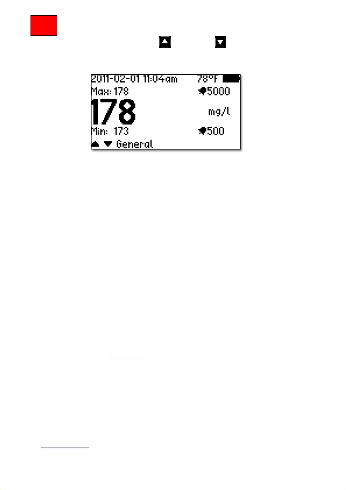
Save a measurement
To save a measurement, or to perform a new measurement, press , when doing this,
an option to save or restart the measurement will be presented. There is a
short command from the text mode display where it is possible to select position for
41
Page 42
Multi
Tracker
storing the measurement. Step up with or down with to reach desired log
position. The postion tag will be shown in the lower margin in the display window. Fig 8
below, shows that the actual profile will be stored at position ”General”
fig 8
It is possible to tag each of the 250 log positions with up to 10 alphanumerical
characters. By entering the log position by tag name, all actual information for the stored
measurement may be retrieved.
Alarm values
At delivery the MultiTracker is preset with the following values; Threshold 1, 500mg/l
(Low suspended solids level) and Threshold 2, 5,000mg/l (High suspended solids level).
Using these values, it is possible to instantly start to measure. To change the settings
please see sections for Threshold 1 and Threshold 2.
Maintenance
The Solido is designed to reduce the manual maintenance to a minimum. All metal parts
are stainless steel (SS 2343/SS316). The enclosure is IP68/NEMA 7. The sensor cable is
a specially manufactured PUR™ with a strong shield and extra heavy wires to withstand
mechanical wear for a long life. The sensor and enclosure cable fittings are high quality
MatchClamp™ to ensure a water proof connection even should the outer shield be
damaged.
Inspection of the sensor
The sensor head should be cleaned if any solids or fouling of the measuring windows
occurs. In order to verify the necessity of cleaning, place the sensor in clean, de-aerated
water and read the display value. The value should not differ more than ±10mg/l from
zero. If the value is off the cleaning is required, a new zero calibration may be
performed. See section Calibration.
When cleaning the sensor, it is preferred to use the Cerlic Sensor Cleaning (CSC) liquid.
It is also possible to use a soft cloth and water. Pay attention not to scratch the optical
windows.
Trouble shooting
In case of any malfunction that is not possible to correct with a new calibration, please
contact Cerlic or a local Cerlic representative. In case of sending the Solido to Cerlic for
checkup or repair, please make sure to use the form for Return of Material (RMA) prior
to dispatch. The RMA document can be downloaded from the Cerlic web page
www.cerlic.com. The WEB page also has the actual and correct receiving address.
42
Page 43

Multi
Tracker
Function
Suspended solids
Measuring principle
Optical light transmission
Wave length
NIR 850 nm
Measuring range
Up to 35,000 mg/l (ppm) dependent
on solids type
Accuracy suspended solids
1% FS (full scale)
Repeatability
< 2% of Measured Value
Type of Measurement
Continuous
Number of Detectable Levels
Two
Measuring units
g/l, mg/l, %, ppm
Temperature Range - Liquid
0 – +50°C (+32 - 122°F)
Sensor Body
Stainless Steel, BK7 Glass Windows
Cable
PUR, Shielded
Cable Fitting
MatchClamp™
Weight Sensor
450g (1 lb)
Dimensions Sensor Body
145mm x 32 mm Ø (5.7”x1.26”Ø)
Cable Length
4 m (13’), 8 m (26 ft), 12 m(36 ft)
Enclosure Sensor Body
IP68 (NEMA 7)
Specification, Solido
43
 Loading...