

Page 1
Page 2

XW110/XW111 User Manual Revisions
Revision Description
0.05 Work in progress, for review only
XW110/XW111 WiFi™ Users Manual
Page 2 Xytronix Research & Design, Inc.
Page 3

XW110/XW111 WiFi™ Users Manual Introduction
Section 1: Introduction
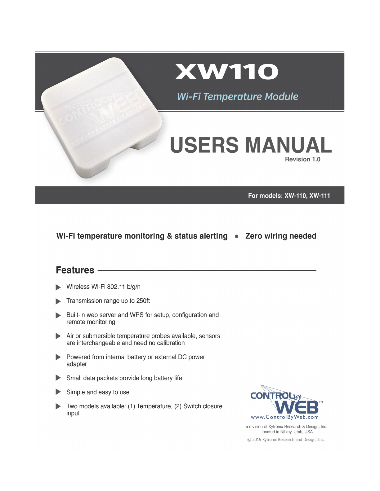
The XW110 and XW111 are easy to use wireless Wi-Fi temperature monitoring and status alerting
devices. The XW-110 measures and reports temperature using a temperature probe which contains a
precision digital sensor. The XW-111 monitors and reports the status of switch closure sensors and
alarms. Both are ideal for applications where temperature or events must be monitored and Ethernet
wiring is not accessible or practical to install.
The modules are powered from either two internal AA batteries or a 5-volt wall transformer. In the case
both are connected, the XW11x will use the wall transformer and automatically switch to the batteries in
the event of a power failure. A three position terminal strip provides connections for a temperature
sensor or up to two switch closure sensors. Not other cables, interfaces or PC utility programs are
needed.
Two user accessible push button switches aid in provisioning the module. Press the “access point”
switch to active the access point mode. With a PC or smart phone you then connect to and access the
internal web server. Using the web server, you may configure the measurement interval, access port,
name and other setup parameters. Alternatively, press the WPS (Wi-Fi Protected Setup) switch on both
the XW11x and your access point to add the XW11x to an existing network.
1.1.1 Features
➢ Wireless Wi-Fi 802.11 b/g/n
➢ Transmission range up to 250ft
➢ Two models available: (1) Temperature, (2) Switch closure input
➢ Built-in web server for configuration and remote monitoring
➢ Temperature sensor is accurate to +/-0.5°C from -10°C to +85°C
➢ Air or submersible temperature probes available, sensors are interchangeable and need no calibration
➢ Powered from two “AA” batteries or external DC power adapter
➢ Small data packets provide long battery life
➢ Simple and easy to use
1.1.2 Part Numbers and Accessories
Device Description Part Number
XW-110
XW-111
Temperature Sensor
Temperature Sensor
Temperature Sensor
Power Supply
Wi-Fi temperature sensor with built-in web server XW-110
Wi-Fi digital input sensor with built-in web server XW-111
Digital temperature sensor with short wire leads
(connects directly to the terminal strip)
Digital temperature sensor with 3 foot wire leads
(housed in submersible stainless steel probe)
Digital temperature sensor with 32 foot wire leads
(housed in submersible stainless steel probe)
Wall Transformer, 120VAC in, 5V, 1A out PS5VW1.0-2.5mm
X-DTS-U
X-DTS-S3C
X-DTS-S32C
Xytronix Research & Design, Inc. Page 3
Page 4

Introduction XW110/XW111 WiFi™ Users Manual
1.1.3 Wireless Communication Notes
Due to the nature of wireless communications, transmission and reception of data can not be
guaranteed. Data may be delayed, have errors or be lost. Although delays or losses of data are rare
with a well constructed network, data can be lost due to interference, noise, reflections or other
environmental conditions. The XW11x should not be used in situations where failure to transmit or
receive data could result in damage to property, equipment, direct, indirect, consequential, or incidental
damage (including damage for loss of business profit, business interruption, loss of data, life, and the
like.)
Page 4 Xytronix Research & Design, Inc.
Page 5
XW110/XW111 WiFi™ Users Manual Installation and Setup
Section 2: Installation and Setup
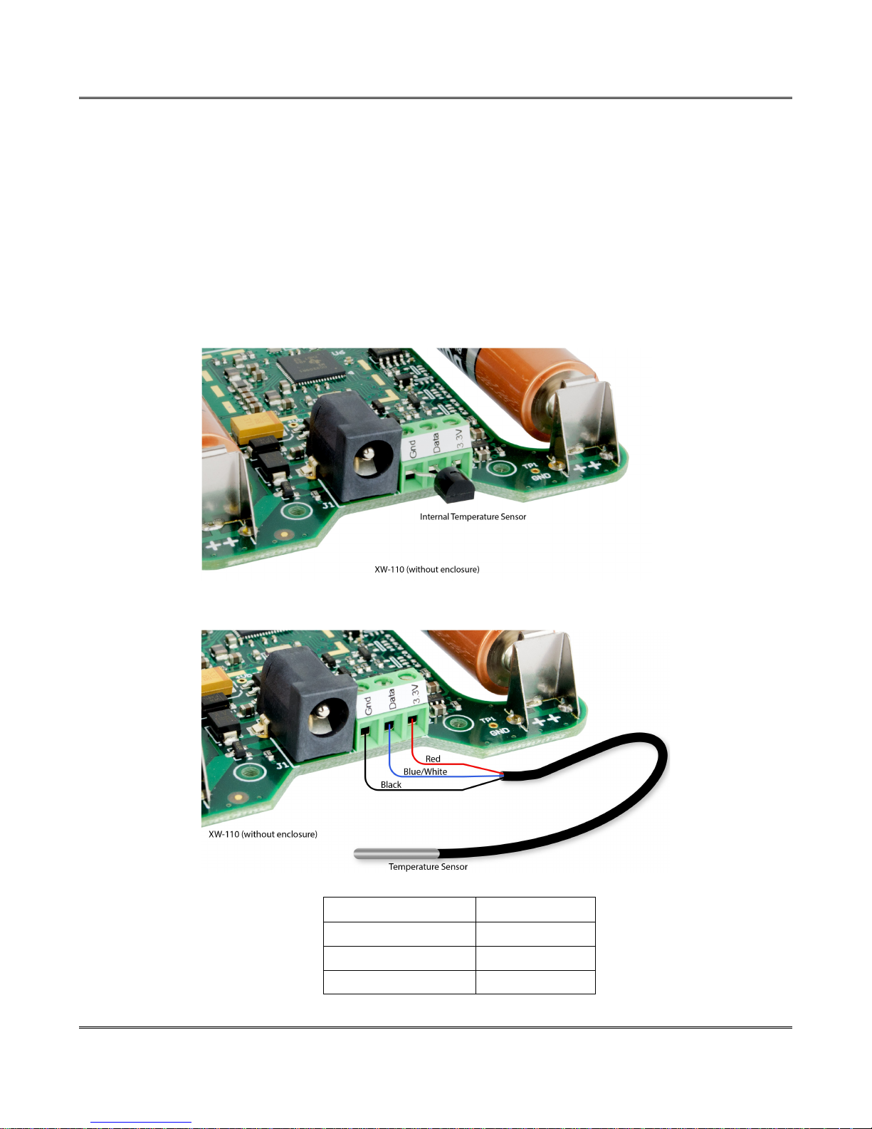
Begin by wiring the sensors to the green 3-terminal strip.
2.1.1 XW-110 Temperature Sensor Connections
The XW-110 works with a specific digital temperature sensor which is interchangeable and requires no
calibration. The sensors accuracy is +/-0.5°C (-10°C to +85°C). The sensor requires three connections
for communications and power (+5V, Ground, Data). The temperature sensor is available in several
configurations. For monitoring room temperature, the bare sensor can be connected directly to the
terminal strip. The rugged version is encapsulated in a stainless steel probe and can be used in
unprotected outdoor locations.
Xytronix Research & Design, Inc. Page 5
Sensor Wire Color Connection
Red +5Vout
Black GND
Blue (or White) Data
Page 6
Installation and Setup XW110/XW111 WiFi™ Users Manual
2.1.2 XW-111 Switch Closure Connections
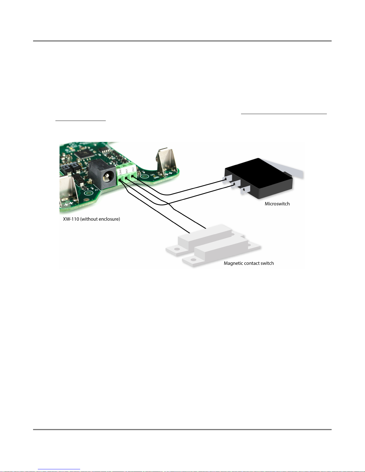
The XW-111 can sense the state of up to two switch closure sensors. Sensors with switch closure
outputs include push buttons, magnetic door alarm switches, micro-switches, or any device which has a
relay or switch closure output. Both sensor inputs share the same GND connection. The XW-111 can be
configured for the alarm to be active when the switch is either open or closed. If possible, use switches
which are normally open (NO). When the switch contact is open no current flows thru the switch and the
longest battery life is achieved. When the switch is closed 17uA flows thru the switch.
The inputs use 3.3Volt logic and work with simple switches and relays. Do not connect the digital inputs
to a power source. The inputs will work with cable lengths up to 50-feet and should not be routed near
motors or AC wiring. The connections for two switches are shown:
2.1.3 Power
The XW-110 and XW-111 are powered from either a 5-volt DC wall adapter or two internal 1.5V “AA”
batteries. If the wall adapter is connected, no power is drawn from the batteries. If the external power
fails the module automatically switches to the internal batteries. No jumpers or switches are needed.
The wall adapter should be used for certain modes with high current demands such as: “Stand-Alone
mode” with HTTP server enabled, “Slave mode” with high reporting rates, or when “access point” is
active.
Page 6 Xytronix Research & Design, Inc.
Page 7
XW110/XW111 WiFi™ Users Manual Installation and Setup
2.1.4 Provisioning
After making the sensor connections and providing power, you must provision the XW11x for use on your
wireless network. The goal is to configure the XW11x such that it can recognize and attach to your Wi-Fi
access point. There are two methods for doing this:
Internal Web Server
The web server requires an active Wi-Fi connection running at full power. It is recommended to use a
wall-transformer with this method or do the configuration quickly as this mode consumes large amounts
of energy. If this is the first time powering the device, it will automatically enumerate as an access-point,
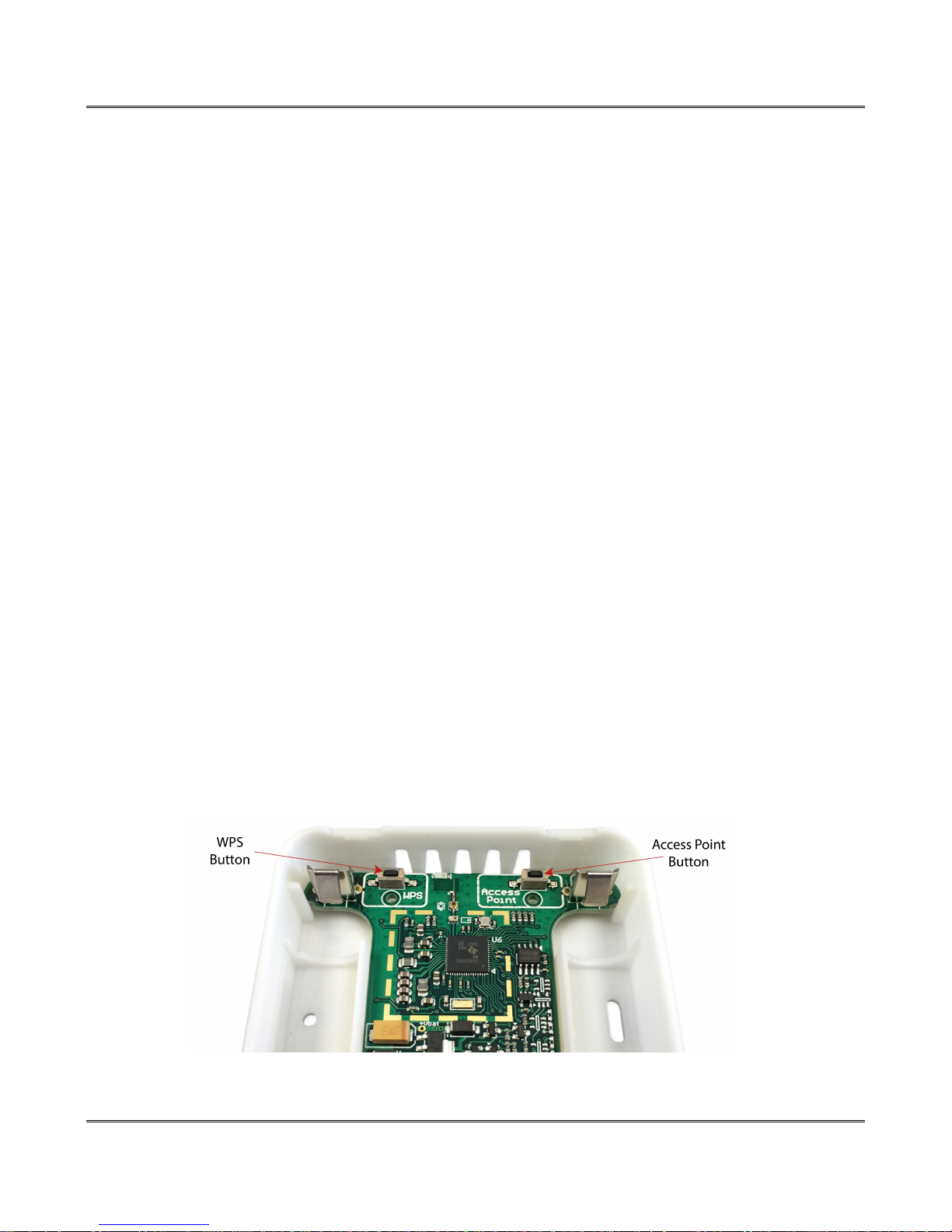
other wise, you must remove the top cover and press the “access point” push button. The XW11x will
awaken and begin broadcasting as an access point. Its SSID is “TempModule-XXXXXX” or
“InputModule-XXXXXX” where XXXXXX are the last six digits of its MAC address. With your wireless
device (laptop computer or smart phone) scan for, and attach to the TempModule or InputModule
wireless network. Next, access the web server in the XW11x using a web browser. To access the setup
pages, enter the following URL in the address bar of your web browser:
http://192.168.1.2/setup.html
After the page is requested, a password prompt will appear. Enter the username and password. The
default username is admin and the default password is webrelay (password is case sensitive). The
following chapter explains each of the setup tabs and screens. Use the WiFi Networks tab for making
the proper settings to allow the XW11x to connect to your access point.
WPS (Wi-Fi Protected Setup)
The WPS Push button method, allows users a simple method for attaching the XW11x to a wireless
network without needing to use any setup pages. To begin, press the WPS button on your wireless router
or access-point. You will generally have about two minutes to connect wireless devices to the network
with WPS. Now remove the cover of the XW11x and press the “WPS” push button. After a few seconds,
the XW11x should register itself with the router or access-point. If the XW11x has not already been
configured, it will use DHCP to obtain an IP address. You will need to access the DHCP server, router, or
access-point to find the IP address it was assigned. Additionally, the connection information is also
broadcast using mDNS. Please note, that the XW11x web server is available with the default
configuration, but will not be if the device has been configured as a slave device or if it has been disabled
for the stand-alone mode.
Xytronix Research & Design, Inc. Page 7
Page 8
Setup Pages XW110/XW111 WiFi™ Users Manual
Section 3: Setup Pages
The XW11x is configured using a web browser. To access the setup pages, enter the following URL in
the address bar of a web browser:
http://192.168.1.2/setup.html
If the XW11x has been added to a network using WPS, it will use DHCP and you will need to use the IP
address assigned to it. This can be found in the DHCP server, or by using mDNS. The mDNS name is
<NAME HERE>.
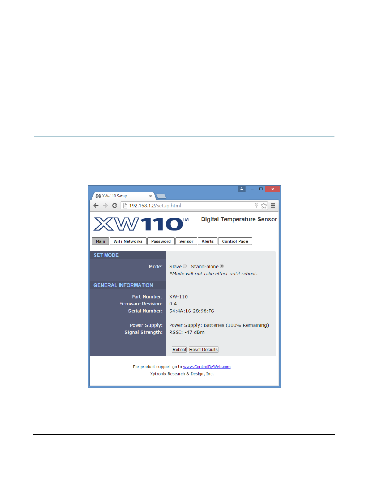
3.1 Main Tab – Stand Alone
This is the initial page that is displayed when setup.html is entered into the address bar of the browser. It
displays model and serial number information, and has navigation tabs which allow access to the
configuration and setup settings. The web pages and communication settings for the XW-110 and XW111 are similar, pages with specific settings for the temperature or digital inputs are shown in the
following sections.
Page 8 Xytronix Research & Design, Inc.
Page 9

XW110/XW111 WiFi™ Users Manual Setup Pages
The XW11x operates in two fundamental modes designated “Slave” and “Stand-alone”. Depending on
this setting the menu tabs change to reflect the relevant settings. Select “Slave” if the XW11x is to make
measurements and send data to a master device such as an X-600™. Select “Stand-Alone” if the
XW11x is to simply monitor the temperature/inputs and/or send e-mail alerts.
The Mode setting will not take effect until the XW11x is rebooted. To do this click the Reboot button after
making a change to the Mode.
Slave:
• In this low power mode the XW11x sleeps most of the time. It periodically awakens, makes
measurements, connects to a WiFi network and transmits data to a CBW device or other server.
• Use longer interval for long battery life.
• Intermittently connects to the wireless network as a Station. If the reporting interval is short, the
WR100 remains connected since the energy required to re-connect is greater than the energy
saved by disconnecting.
• No Emails are supported
• The Alert tab is suppressed, Remote Master tab is shown
• The internal web server is not accessible
Stand-Alone:
• Operates as a Station which allows the XW11x to be part of another wireless network.
• Periodically makes measurements and sends email alerts only when alarm conditions are
satisfied.
• Alarms and Emails are supported.
• The Alert tab is visible and Remote Master is suppressed.
• The internal web server is accessible at the option of the user. Enabling the internal web server
requires an active connection to the access point and is not feasible with battery operation.
Access Point:
• As an Access Point the XW11x functions independently of other wireless networks. It broadcasts
beacons and services WiFi packet requests.
• Connect to the XW11x access point with any WiFi enabled phone or laptop computer.
• Used for provisioning the XW11x.
• Periodically makes measurements and displays the data on its internal web page. Data is not
sent to other networks.
• Access Point works best when powered from a 5-volt DC wall adapter.
Xytronix Research & Design, Inc. Page 9
Page 10

Setup Pages XW110/XW111 WiFi™ Users Manual
Part Number
This is the full model number of the XW11x
Firmware Revision
This is the current product revision of the internal software
Serial Number
This is the serial number of the XW11x. The serial number is also the MAC address of the unit.
Power Supply
This field shows if the XW11x is currently being powered by batteries or the DC wall transformer. If
running on batteries, the battery voltage is measured and an estimate is made of the remaining battery
life. The calculations are made for alkaline “AA” batteries with a usable capacity of 2000mAH. When
using other batteries or in cold conditions the displayed estimate may be in error.
Signal Strength
This indicates the current receive Wi-Fi signal strength. The more negative the number the less signal is
being received. -30dBm is a strong signal, and -90dBm is a very weak signal.
Reboot
After showing a confirmation page, this button will send a command to reboot the device.
Reset Defaults
After showing a confirmation page, this button will erase all user settings and return the device to factory
defaults.
Page 10 Xytronix Research & Design, Inc.
Page 11
XW110/XW111 WiFi™ Users Manual Setup Pages
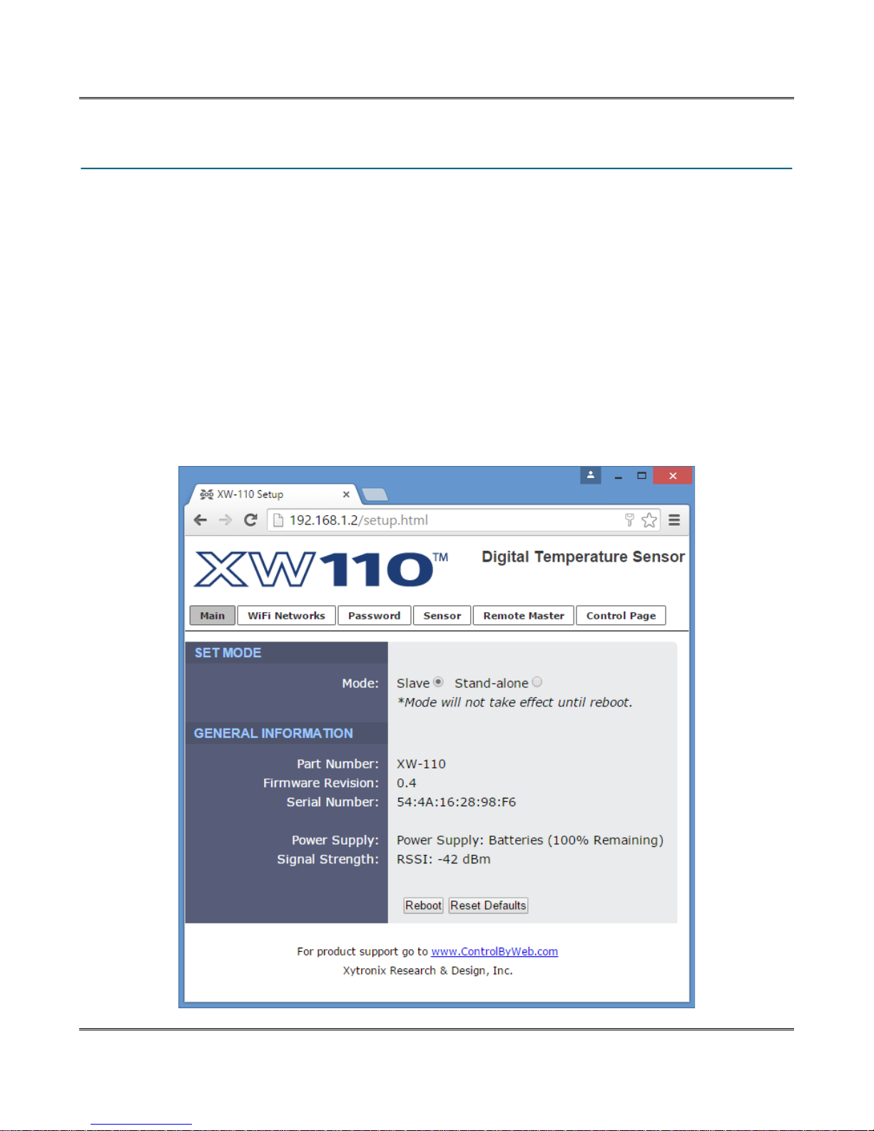
3.2 Main Tab – Slave
This tab is identical to the tab described above (Main Tab - Stand Alone) with the exception that the
Slave mode has been selected. With Slave selected, the Alert tab is replaced by the Remote Master
tab.
Select “Slave” if the XW11x is to make measurements and send data to a master device such as an X600™. In this mode, the XW11x sleeps most of time conserving battery power. It periodically awakens,
makes simple measurements and transmits (pushes) the data to a remote server. Access the Remote
Master tab to select how often measurements are made and to which server the data is to be sent.
The Mode setting will not take effect until the XW11x is rebooted. To do this click the Reboot button after
making a change to the Mode.
In the low power Slave mode the web server is no longer accessible. To make subsequent changes you
must remove the top cover and press the “access point” push button to force the XW11x into a state
where you can connect to and access the internal web server again.
Xytronix Research & Design, Inc. Page 11
Page 12
Setup Pages XW110/XW111 WiFi™ Users Manual
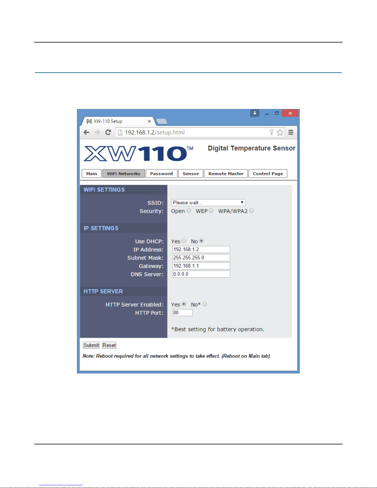
3.3 WiFi Networks Tab
As a Wi-Fi slave device, the XW11x attempts to automatically connect to configured Wi-Fi access points.
The settings on this page tab are used to configure this connection.
SSID
The SSID (Service Set Identifier) is the name of your WiFi network.
Security
Type of authentication used by the access point for connections.
Page 12 Xytronix Research & Design, Inc.
Page 13

XW110/XW111 WiFi™ Users Manual Setup Pages
Security Key
Enter the security key or password for the WiFi network to connect to. (Hidden when not applicable)
Use DHCP
This option allows DHCP to be enabled or disabled. If this option is set to Yes, the XW11x will wait for an
IP address from a DHCP server each time it is powered. The default setting is No (this is recommended
for most installations). If DHCP is set to Yes, the Network page must be submitted and the XW11x must
be rebooted before an IP address will be assigned. Once the XW11x is assigned an IP address by the
DHCP, the new IP address can be found through the clients list kept by the DHCP server. For most
instances, this is found on the local gateway or router. By not using DHCP, battery life is extended as the
device does not need energy for transmitting requests and receiving responses every time it connects to
the WiFi network.
Brief Notes About DHCP
All devices on an IP network require an IP address. This is a unique address that identifies each device
on the network. DHCP (Dynamic Host Control Protocol) is a mechanism that automatically assigns an IP
address to a computer (or other devices) when it is connected to a network. This eliminates the need to
manually enter the IP address. When a computer is connected to the network, another device on the
network called a DHCP server detects the presence of the computer and dynamically assigns the IP
address to that computer. On many small networks, the DHCP server is built into the router.
DHCP works well for "client" devices such as computers, but is not ideal for servers. This is because
servers usually don't initiate communications with other devices, but rather they wait for a request from
"clients." To make this request, the client must know the IP address of the server. If a server gets its IP
address dynamically, the IP address may not always be the same so client devices may not be able to
find the server. For this reason, servers usually use an IP address that is fixed and does not change. The
XW11x is a server and manual IP address assignment is usually recommended.
HTTP Server Enabled
This option can turn the internal HTTP web server on or off. Turning the web server off will allow the
device to make use of more power saving features. With the web server turned off, the device will be
allowed to disconnect from the WiFi network or at the very least service beacons selectively.
HTTP Port
The TCP port used for HTTP communications with the XW11x can be customized here. The default
setting for this field is 80, which is the standard HTTP port. It is recommended that the port be left
unchanged unless the user has an understanding of TCP/IP and ports.
Xytronix Research & Design, Inc. Page 13
Page 14
Setup Pages XW110/XW111 WiFi™ Users Manual
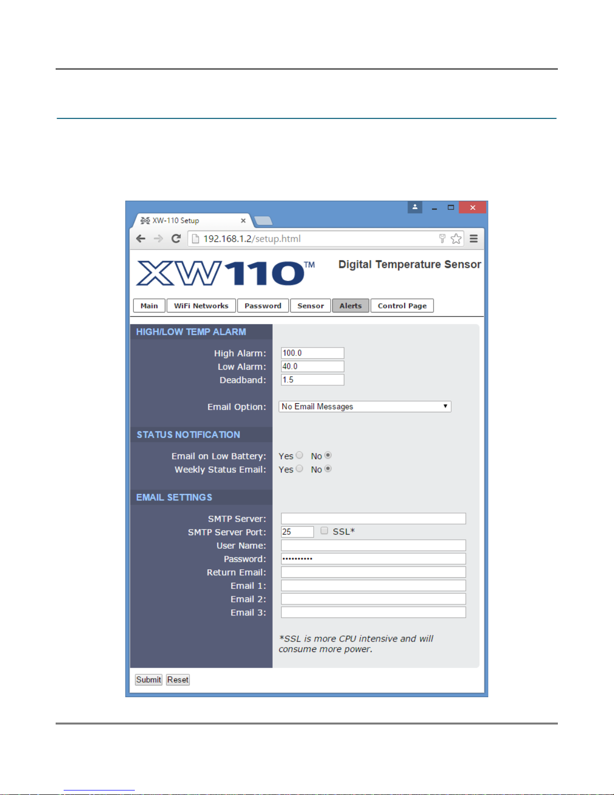
3.4 Alerts & Email Tab
When configured as a Stand-Alone device this tab is visible. This page determines when alarm (alert)
events occur and what actions are to be taken. Up to three Email addresses can be assigned for alerts.
The same message is sent to each Email address. For Email notification to work, the XW11x must have
a properly configured network connection and a SMTP server must be defined.
Page 14 Xytronix Research & Design, Inc.
Page 15
XW110/XW111 WiFi™ Users Manual Setup Pages
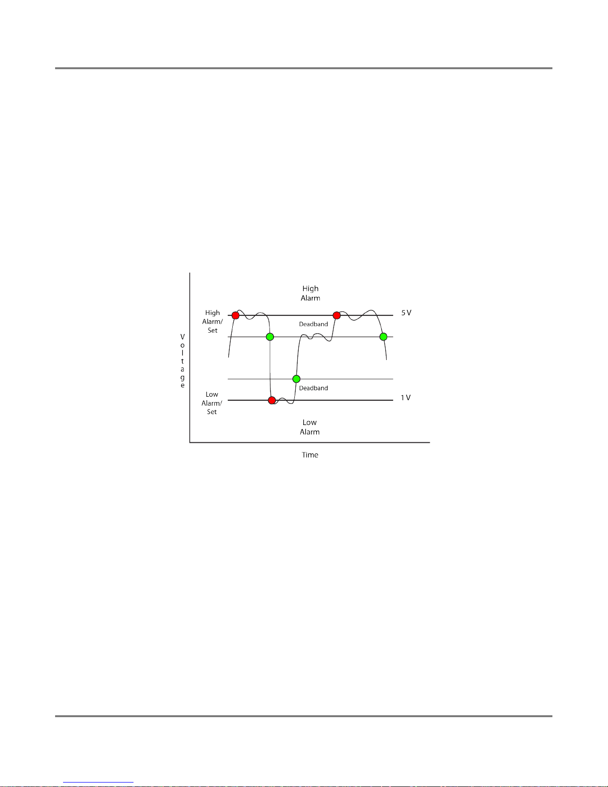
High Alarm
A high alarm is triggered when the temperature exceeds this set point.
Low Alarm
A low alarm occurs when the temperature is lower than this set point.
Deadband
The deadband (hysteresis) prevents conditions and alarms from triggering excessively when the
measurement value vacillates around the trigger point. With high alarms, the measurement must fall
below the high alarm point minus the dead band before the high alarm will be triggered again. Likewise
the deadband on the low alarm requires the measurement to rise above the low alarm point plus the
deadband before the low alarm will be triggered again.
For example, if the dead band is set to 0.5°C, and a high alarm is set at 13°C - the high alarm will occur
at 13°C; however, it will not turn off until the temperature drops below 12.5°C (13°C - 0.5°C).
Email Option
Simple email messages can be sent in response to alarm conditions. This parameter is used to specify
what alarm conditions, if any, will cause email messages to be sent. Email notifications will work only if
email is correctly setup in the following settings.
No Email Messages: No email messages will be sent due to alarm conditions.
Send Email on High Alarm: Email notifications will be sent due to a High Alarm condition.
Send Email on Low Alarm: Email notifications will be sent due to a Low Alarm condition.
Send Email on High and Low Alarm: Email notifications will be sent due to a High or Low Alarm condition.
Send Email on High, Low and Normal Alarm: Email notifications will be sent due to a High or Low alarm
condition or when Normal conditions are restored.
Email on Low Battery
When a low battery condition occurs an email message is sent to this address. To conserve already
meager energy resources, only one low battery message is sent.
Xytronix Research & Design, Inc. Page 15
Page 16

Setup Pages XW110/XW111 WiFi™ Users Manual
Weekly Status Email
When checked, the XW11x will send an email once a week with temperature and battery information.
This is to assure the user the unit is functioning properly.
SMTP Server
The SMTP mail server host name.
SMTP Server Port
The port number of the SMTP mail server. This is generally 25 for non encrypted SMTP servers. If using
SSL/TLS, this port number is generally 465.
SSL Checkbox
Check this checkbox if the server and port you have configured is expecting a SSL/TLS connection.
User Name
Email user name (if required)
Password
Email password (if required)
Return Email
The emails address that will get notification if the sent email does not get sent.
Email 1
When an alert occurs an Email message is sent to this address
Email 2
When an alert occurs an Email message is sent to this address
Email 3
When an alert occurs an Email message is sent to this address
Page 16 Xytronix Research & Design, Inc.
Page 17
XW110/XW111 WiFi™ Users Manual Setup Pages
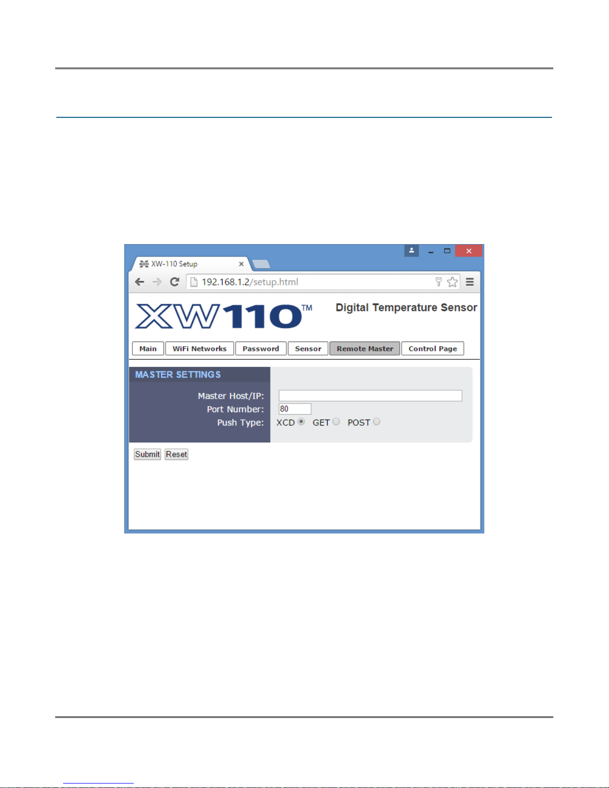
3.5 Remote Master Tab
When configured as a Slave device this tab is visible. In this low power mode the XW11x periodically
awakens, makes simple measurements and transmits (pushes) the data to a remote server. This tab is
used to set how often measurements are made and to which server the data is to be sent. No alarms or
Emails are supported and the web server is inactive.
To save power in the Slave mode the XW11x normally disconnects from the access point. If the sleep
interval is less than 63-seconds the XW11x automatically remains connected since the energy required
to re-connect is greater than the energy saved by disconnecting.
Master Host/IP
The URL or IP address of the server you wish to send (push) data to.
Port Number
The TCP port used for communications with the remote server.
Push Type
Data is sent to the remote server with one of three HTTP protocols:
XCD Method (Xytronix Compact Data)
This method is used to send data to Xytronix devices such as the X-300. The CBW
method condenses the information into binary data to reduce the amount of energy
needed by the XW11x to transmit the information.
Xytronix Research & Design, Inc. Page 17
Page 18

Setup Pages XW110/XW111 WiFi™ Users Manual
GET Method
The HTTP GET method is used to send the data to the path specified in the Path field.
The Path field is hidden unless the GET or POST methods are selected.
POST Method
The HTTP POST method is used to send the data to the path specified in the Path field.
The Path field is hidden unless the GET or POST methods are selected.
Path
Location of a script or page that can accept the data being sent via POST or GET. (Only appears when
GET or POST method is selected). For example, if the script is located at
www.yourdomain.com/logger.php, the path would be logger.php
Page 18 Xytronix Research & Design, Inc.
Page 19
XW110/XW111 WiFi™ Users Manual Setup Pages
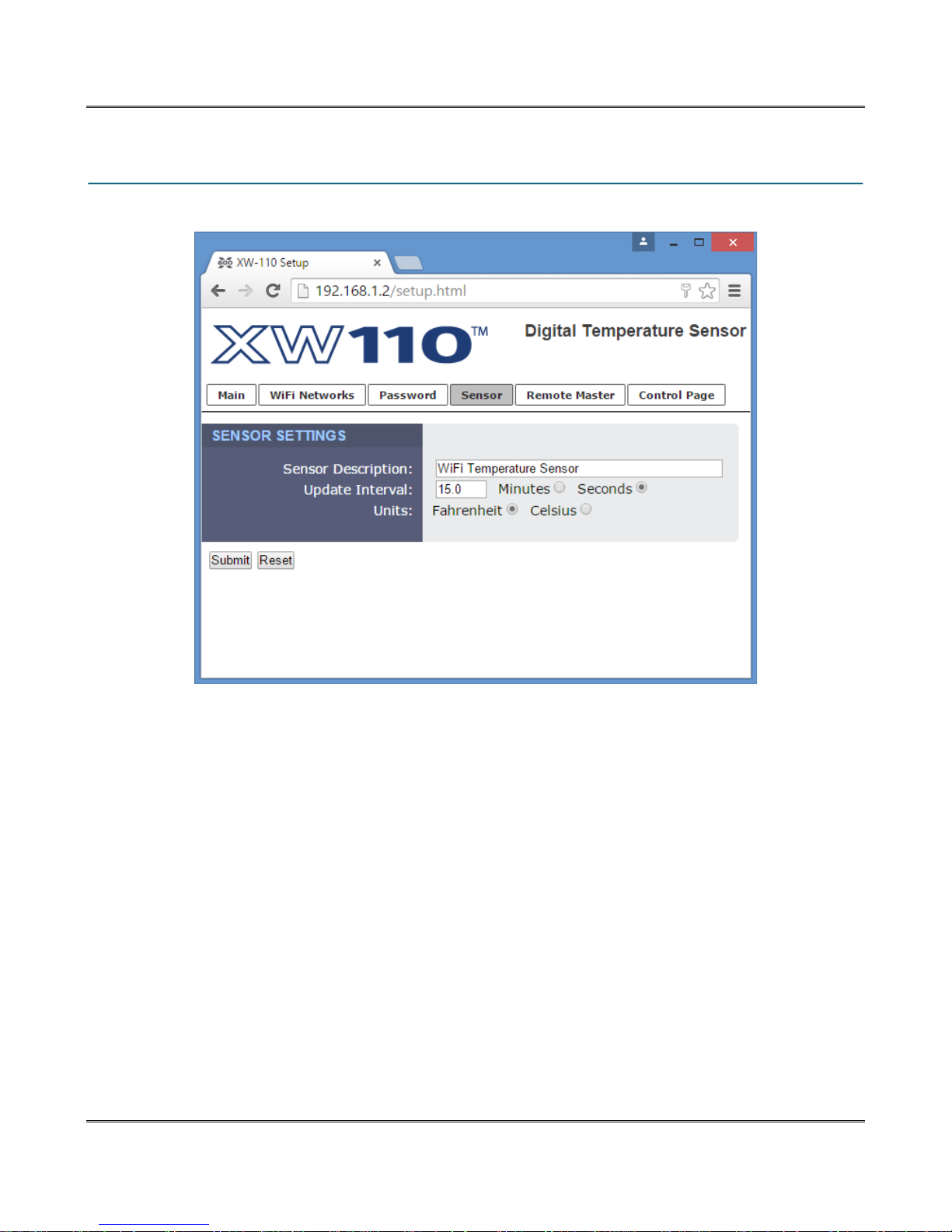
3.6 Temperature Sensor Tab
Sensor Description
This text will appear in email messages when email alerts are enabled as well as on the Control Page.
This field may be up to 35 characters long.
Update Interval
The XW110 normally operates in a low power sleep mode and is programmed to periodically awaken
and measure the temperature. This setting selects how often this occurs. When operating from a DC
wall power supply this setting can be set to most any value. Realize that every measurement requires
energy from the battery. To obtain the best battery life set the update for as long as possible for your
application. For example, when monitoring the temperature of a freezer use 15 minutes or so, for
outdoor temperature which changes slowly use a longer interval such as 30 minutes.
Xytronix Research & Design, Inc. Page 19
Page 20

Setup Pages XW110/XW111 WiFi™ Users Manual
Units
This allows the user to select between the temperature units of Fahrenheit and Celsius. All settings
entered and displayed on subsequent pages will be in the units selected.
Page 20 Xytronix Research & Design, Inc.
Page 21

XW110/XW111 WiFi™ Users Manual Setup Pages
3.7 Digital Input Sensor Tab
Screenshot needed
Sensor Description
This text will appear in email messages when email alerts are enabled as well as on the Control Page.
This field may be up to 35 characters long.
Update Interval
The XW111 normally operates in a low power sleep mode and is programmed to periodically awaken and
test the state of the digital inputs. This setting selects how often this occurs. When operating from a DC
wall power supply this setting can be set to most any value. Realize that every measurement requires
energy from the battery. To obtain the best battery life set the update for as long as possible for your
application.
Xytronix Research & Design, Inc. Page 21
Page 22
Setup Pages XW110/XW111 WiFi™ Users Manual
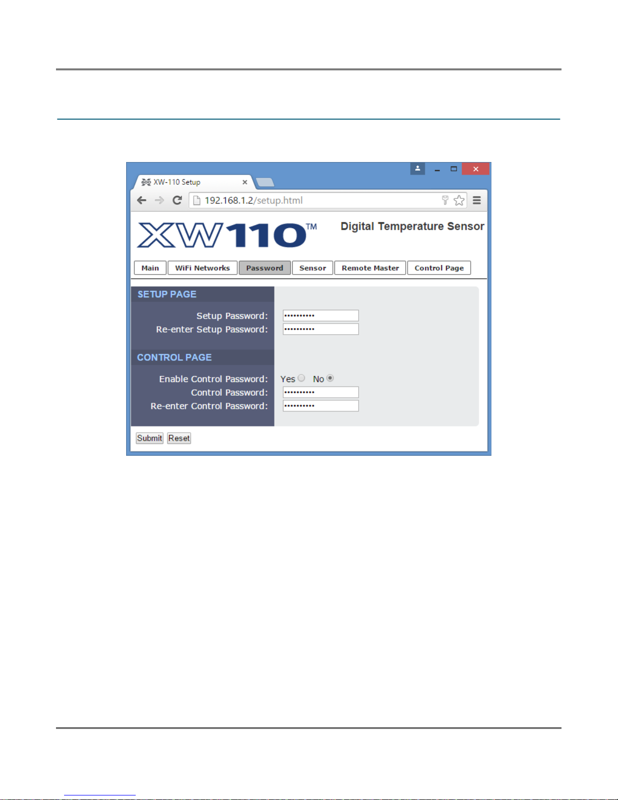
3.8 Password Tab
The XW11x requires a password to log into the Setup or Control pages. The password is the same for
all pages. The password can be changed on this page.
Setup Password
The Setup Password, which is required to access the setup pages, can be modified by entering a new
password here. Passwords that are 8 characters or longer (up to 13 characters can be entered in this
field) with both alphabetic and numeric characters are recommended. For security purposes, the
password will not be displayed as it is entered.
Re-enter Setup Password
When the Setup Password is changed, it must be entered twice. One time in the previous field and a
second time in this field. If the password is not entered identically in both fields, the password will not be
changed.
Enable Control Password
The Web Pages can be normally viewed without entering a password. For security purposes, a password
can be enabled. When this field is set to Yes, a password will be required to view any of the pages. The
default setting for this field is No.
Control Password
The Password, which is required to access the Control Page pages, can be modified by entering a new
password here. Passwords that are 8 characters or longer (up to 13 characters can be entered in this
Page 22 Xytronix Research & Design, Inc.
Page 23

XW110/XW111 WiFi™ Users Manual Setup Pages
field) with both alphabetic and numeric characters are recommended. For security purposes, the
password will not be displayed as it is entered.
Re-enter Control Password
When the Control Password is changed, it must be entered twice. One time in the previous field and a
second time in this field. If the password is not entered identically in both fields, the password will not be
changed.
Xytronix Research & Design, Inc. Page 23
Page 24
Operation XW110/XW111 WiFi™ Users Manual
Section 4: Operation
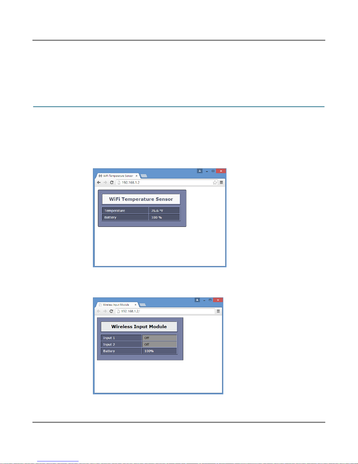
In the stand alone mode the temperature or digital input status can be monitored by using a web
browser, the CBW Mobile app, and/or by sending text commands to an XML status/control page when
the internal web server is enabled.
4.1 Browser Operation
Once the XW11x is set up, users can access the Control Page using a web browser by typing the IP
address of the XW11x into the web browser address bar. For example, using the default IP address, the
user would enter http://192.168.1.2. If the IP address is changed from the default, the user must use the
new IP address. Note that if any port is used other than the default port 80, the port must also be
included in the request. For example, to access the device at port 8000 enter: http://192.168.1.2:8000.
4.1.1 XW-110 Temperature Sensor Display
4.1.2 XW-111 Digital Input Display
Page 24 Xytronix Research & Design, Inc.
Page 25
XW110/XW111 WiFi™ Users Manual Appendix A: XCD Packet Format
Appendix A: XCD Packet Format
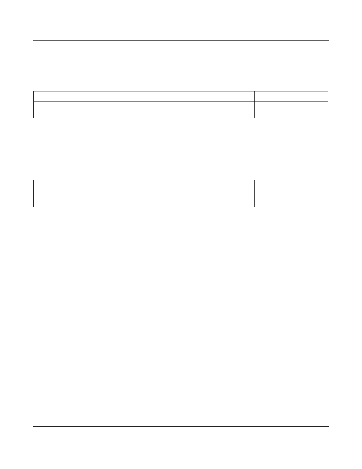
The XW-110 and XW-111 sensors send data contained in a TCP/IP packet. To keep the packets small
they are not HTTP.
XS-110 Temperature Sensor Packet
Function Code MAC Address Battery Temperature
1 byte 6 bytes 1 byte (MSb identifies 5V
power)
Where:
Cmd: (1-byte) 1-byte format identifier
Data:
XS-111 Digital Sensor Packet
Function Code MAC Address Battery Temperature
1 byte 6 bytes 1 byte (MSb identifies 5V
power)
4 byte IEEE-754 floating
point number
4 byte IEEE-754 floating
point number
Where:
Cmd: (1-byte) 1-byte format identifier
Data:
Xytronix Research & Design, Inc. Page 25
Page 26

Appendix B: Specifications XW110/XW111 WiFi™ Users Manual
Appendix B: Specifications
Wireless Specifications
Network Standards: IEEE 802.11 b/g/n
Frequency Band 2.412 – 2.462 GHz
Wi-Fi Security Standards Open, WEP, WPA, WPA2
Network Settings: DHCP or Static
Wireless Range Up to 250ft (typical for Wi-Fi devices) depends on environment
Antenna: Integral chip antenna, 1.9 dBi.
RF Output Power (typ) 14dBM (802.11b/g), 12dBM (802.11n)
Operation
Provisioning: Via internal web server (no cables or PC utilities needed)
Access Point: Yes, push button activated (setup via web page)
WPS: Yes, push button activated (Wi-Fi Protected Setup)
Connectivity: Intermittently connected or always connected
XCD Data Packet: UDP, 10-bytes (See Appendix A)
Remote Server: ControlByWeb™ X-600™, X-300™ or cloud based server
Polling: state.xml (only with always-connected)
Power
External: 5VDC ±10%, 500ma max (via DC power wall adapter)
DC Jack: 5.5mm barrel x 2.5mm center pin (positive)
Internal: Two replaceable 1.5V “AA” cells (included)
Power Consumption 27-770uA sleep, 59mA active RX, 229mA TX (at +12dBm)
Battery Life Up to 3-years, depending on mode, security and reporting frequency
Battery Usage Battery voltage is measured and periodically reported
Transmissions: Up to xxx,xxx transmissions (intermittently connected)
Up to xxx,xxx transmissions (always connected)
Internal Push Buttons
Button 1: Force access-point mode
Button 2: Activate WPS mode
Sensor Inputs
Model XW-110: Digital “1-wire” thermometer probe
Interchangeable, no calibration needed
Dallas Semiconductor DS18B20 digital 1-wire thermometer
+/-0.5°C from -10°C to +85°C
Available in non-submersible (air) or submersible versions
Maximum cable length 600 ft (180m)
Model XW-111: Two switch closure inputs
Vin Max = +3.3V, Internal pullup = 200K
Vin HI = 2.8V (min), Vin LO =1.0V (max)
Max cable length 50 ft (use relay isolation for longer runs)
Configuration
Celsius/Fahrenheit: User configurable
Temperature Reports: Interval, temperature change (delta), or both
Switch Status Reports:: Interval, on state change, or both
Page 26 Xytronix Research & Design, Inc.
Page 27
XW110/XW111 WiFi™ Users Manual Appendix B: Specifications
Report Frequency: User configurable
Email Alerts: Yes
Encrypted Email Alerts: Yes
SMS Message: No
Environmental
Location: Indoor use or NEMA-4 protected location
Using Alkaline Batteries: -18ºC to 55ºC (0ºF to 130ºF)
Operating Temperature: -40ºC to 65ºC (-40ºF to 150ºF)
Storage Temperature: -40ºC to 85ºC (-40ºF to 185ºF)
Humidity: 5-95%, non-condensing
Mechanical
Mounting: Wall mount
Material Polycarbonate plastic
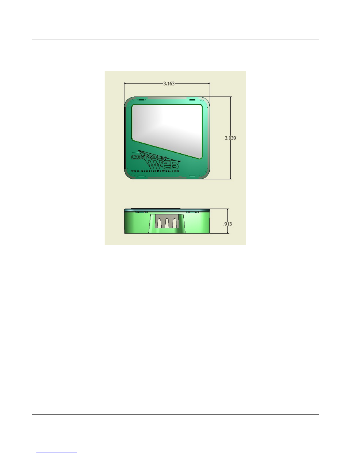
Size: 3.16 x 3.04 x 0.91 in. [80 x 77 x 23mm]
Weight: 2.4 oz [68g], no batteries
Certifications
FCC ID: 2AE4Z-XWD001
FCC 47CFR15 (Class B)
IEC CISPR 22, CISPR 24
EN55024 ITE Immunity (2010)
EN55022 Emissions (2010)
Xytronix Research & Design, Inc. Page 27
Page 28

Appendix C: Trademark and Copyright Information XW110/XW111 WiFi™ Users Manual
Appendix C: Trademark and Copyright Information
This document is Copyright ©2015 by Xytronix Research & Design, Inc. All rights reserved.
XW11x™, WebRelay™, ControlByWeb™, and Xytronix Research & Design™ are trademarks of Xytronix
Research & Design™, Inc. 2005-2015.
All other trademarks are the property of their respective owners.
All parts of this product and design including but not limited to firmware, hardware design, schematics,
PCB layout, concept, graphics, users manual, etc., are property of Xytronix Research & Design, Inc.
©2005-2015. XW11x™ may not be copied or reverse-engineered.
No part of this manual may be reproduced or transmitted in any form or by any means, electronic or
mechanical, including photocopying or scanning, for any purpose other than the personal use by the
purchaser of this product. Xytronix Research & Design, Inc., assumes no responsibility for any errors that
may appear in this document.
Whereas reasonable effort has been made to make the information in this document as useful and
accurate as possible, Xytronix Research & Design, Inc. assumes no responsibility for the application,
usefulness, or completeness of the information contained herein. Under no circumstance will Xytronix
Research & Design, Inc. be responsible or liable for any damages or losses including direct, indirect,
special, incidental, or consequential damages or losses arising from either the use of any information
contained within this manual or the use of any products or services referenced in this manual.
Xytronix Research & Design, Inc. reserves the right to change any product’s features, specifications,
documentation, warranties, fee schedules, and conditions at any time and without notice.
Page 28 Xytronix Research & Design, Inc.
Page 29

XW110/XW111 WiFi™ Users Manual Appendix D: Warranty
Appendix D: Warranty
This Xytronix Research & Design, Inc. product has a warranty against defects in material and
workmanship for a period of one year from the date of shipment. During the warranty period, Xytronix
Research & Design, Inc. will, at its option, either repair or replace products that prove to be defective.
This warranty is extended to the original purchaser of the equipment only.
For warranty service or repair, the product must be properly packaged, and returned to Xytronix
Research & Design, Inc. The purchaser shall prepay all charges for shipping to Xytronix Research &
Design, Inc., and Xytronix Research & Design, Inc. will pay the shipping charges to return the product to
the purchaser as long as the product is shipped within the United States. If the product is shipped outside
of the United States, the purchaser shall pay all shipping charges, duties, and taxes.
Limitation
The foregoing warranty shall not apply to defects or damage resulting from improper use or misuse,
unauthorized repair, tampering, modification, improper connection, or operation outside the
electrical/environmental specifications for the product. Further, the warranty does not cover Acts of God,
such as fire, flood, hurricanes, and tornadoes. This warranty does not cover damage to property,
equipment, direct, indirect, consequential, or incidental damage (including damage for loss of business
profit, business interruption, loss of data, and the like) arising out of the use or misuse of this product.
UNDER NO CIRCUMSTANCES WILL THE LIABILITY OF XYTRONIX RESEARCH & DESIGN, INC. TO
THE PURCHASER OR ANY OTHER PARTY EXCEED THE ORIGINAL PURCHASE PRICE OF THE
PRODUCT, REGARDLESS OF THE FORM OF THE CLAIM. No other warranty is expressed or implied.
Xytronix Research & Design, Inc. specifically disclaims the implied warranties or merchantability and
fitness for a particular purpose. Some jurisdictions may not allow the exclusion of limitation of liability for
consequential or incidental damage.
Xytronix Research & Design, Inc. Page 29
Page 30

Appendix E: FCC Statement XW110/XW111 WiFi™ Users Manual
Appendix E: FCC Statement
This device complies with Part 15 of the FCC Rules. Operation is subject to the following two conditions:
1. This device may not cause harmful interference.
2. This device must accept any interference received, including interference that may cause
undesired operation.
Warning
This equipment has been tested and found to comply with the limits for a Class B digital device, pursuant
to part 15 of the FCC Rules. These limits are designed to provide reasonable protection against harmful
interference in a residential installation. This equipment generates, uses and can radiate radio frequency
energy and, if not in-stalled and used in accordance with the instructions, may cause harmful
interference to radio communications. However, there is no guarantee that interference will not occur in a
particular installation. If this equipment does cause harmful interference to radio or television reception,
which can be determined by turning the equipment off and on, the user is encouraged to try to correct the
interference by one or more of the following measures:
- Reorient or relocate the receiving antenna.
- Increase the separation between the equipment and receiver.
- Connect the equipment into a relay on a circuit different from where the receiver is connected.
- Consult the dealer or an experienced radio/TV technician for help.
Notice
Changes or modification not expressly approved by the party responsible for compliance could void the
user’s authority to operate the equipment.
RF Exposure Information
This equipment complies with the FCC RF radiation exposure limits set forth for an uncontrolled
environment. The antennas used with this transmitter must be installed to provide a separation distance
of at least 20cm from all persons and must not be located or operating in conjunction with any other
antenna or transmitter.
Canadian License-Exempt Radio Apparatus (RSS-GEN)
This device complies with Industry Canada licence-exempt RSS standard(s). Operation is subject to the
following two conditions: (1) this device may not cause interference, and (2) this device must accept any
interference, including interference that may cause undesired operation of the device.
Le présent appareil est conforme aux CNR d'Industrie Canada applicables aux appareils radio exempts
de licence. L'exploitation est autorisée aux deux conditions suivantes : (1) l'appareil ne doit pas produire
de brouillage, et (2) l'utilisateur de l'appareil doit accepter tout brouillage radioélectrique subi, même si le
brouillage est susceptible d'en compromettre le fonctionnement.
Page 30 Xytronix Research & Design, Inc.
Page 31
XW110/XW111 WiFi™ Users Manual Appendix F: Mechanical Dimensions
Appendix F: Mechanical Dimensions
Xytronix Research & Design, Inc. Page 31
 Loading...