

Page 1

Page 2
Introduction XW-210 WiFi™ Users Manual
Section 1: Introduction
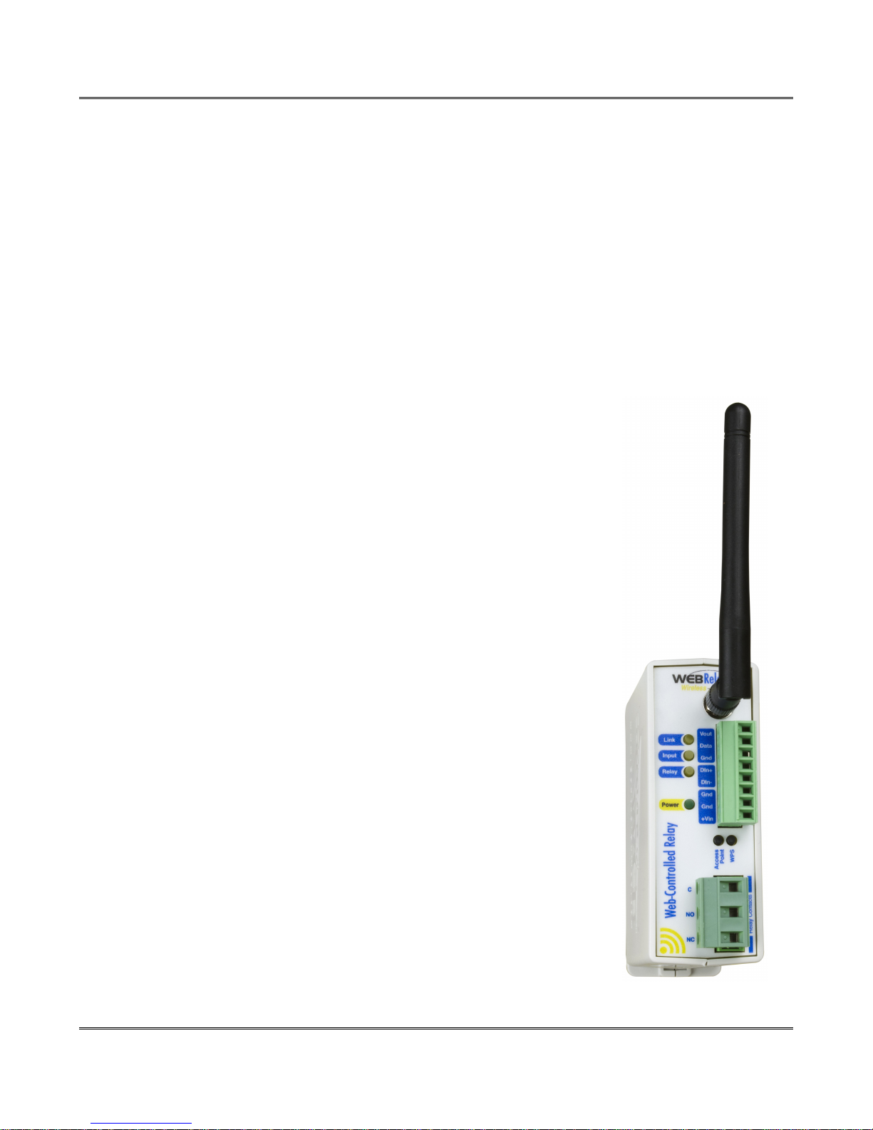
The XW-210™ is an easy to use Wi-Fi enabled relay, temperature monitor and status alerting device.
The XW-210 has a built-in relay for controlling lights, motors and other relatively high current loads, a
digital input which can be used to monitor and report the status of switch closure sensors and a “1-wire”
port for connecting up to four digital temperature or other Xytronix 1-wire sensors. The XW-210 is ideal
for applications where devices must be controlled or where temperature or events must be monitored
and Ethernet wiring is not accessible or practical to install. The module is powered by an external wall
transformer (9-28 VDC), solar panel, or other DC power source.
The XW-210 works well as a standalone device that can be controlled using a web browser. It can be
configured using simple menus and drop-down lists. It includes features such as logging, input state
monitoring, and the ability to control other relays on other devices.
The XW-210 can be a self-contained wireless access point that requires no additional servers or
ControlByWeb devices. In this mode the XW-210 provides live, real-time temperatures or input status
directly to a single user through web browsers or the CBW Mobile app.
After being commissioned the XW-210 can recognize and attach to your WiFi access point. The XW-210 offers the ability to control it's relay, monitor
temperature or input status and send out email alerts (which can be converted
to text message alerts) whenever an alarm condition occurs.
Plug-in terminal strips provide connections for the DC power, relay contacts,
optically isolated input and up to 4-temperature or other Xytronix 1-wire
sensors. No other cables, interfaces, or PC utility programs are needed.
Two push-button switches aid in provisioning the module. Press the “Access
Point” button anytime to active the access point mode. With a WiFi enabled
PC or smart phone you then connect to and access the internal web server at
the default IP address, port and password. Using the web server, you
configure the access port, name, and other setup parameters. Alternatively,
add the XW-210 to an existing network by pressing the “WPS” (Wi-Fi
Protected Setup) button on both your access point (i.e., router) and the XW-
210.
The XW-210 supports a number of Ethernet protocols with it's built-in server,
including HTTP, Modbus/TCP, NTP, and XML.
The XW-210 has a built-in BASIC interpreter. A control script can be written
for special needs or custom applications not provided by the normal control
functions.
Page 2 Xytronix Research & Design, Inc.
Page 3

XW-210 WiFi™ Users Manual
1.1 Features
➢ Wireless Wi-Fi 802.11 b/g/n.
➢ Transmission range up to 250ft.
➢ Built-in web server for configuration and remote monitoring.
➢ Built-in high current relay.
➢ Optically isolated digital input. Use the input to control relays or trigger email messages.
➢ Pulse counter.
➢ “1-wire” port for connecting up to 4 digital temperature or other Xytronix 1-wire sensors.
➢ Temperature sensors are accurate to +/-0.5°C from -10°C to +85°C.
➢ Temperature probes are interchangeable and need no calibration.
➢ Powered from a 9 to 24V DC power adapter. The power supply voltage is monitored internally and can be
logged.
➢ Sensor/Input status can control a relay on other ControlByWeb devices.
➢ Configurable logging of the input, counter, temperature, humidity, relay state and Vin.
➢ Real-time clock with manual or NTP time sync.
➢ Send email alerts (up to 8 addresses) based on any sensor or input conditions.
➢ Auxiliary protocols including XML, Modbus/TCP and Remote Services.
➢ Custom scrips using the built-in BASIC interpreter provide additional flexibility.
➢ Simple and easy to use.
➢ 5-year warranty.
Xytronix Research & Design, Inc. Page 3
Page 4
Introduction XW-210 WiFi™ Users Manual
1.2 Part Numbers and Accessories
Device Description Part Number
XW-210
Wi-Fi WebRelay with built-in web server XW-210I
Temperature Sensor
Temperature Sensor
Temperature Sensor
Temperature/
Humidity Sensor
(Wall Mount)
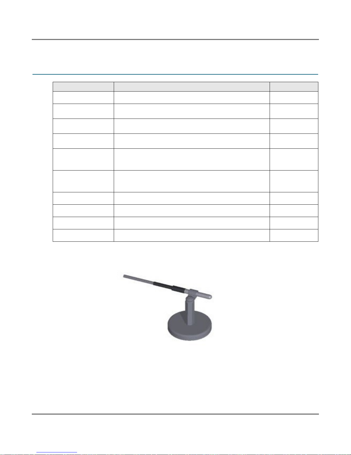
Magnetic
Temperature Sensor
Mount
Power Supply
Water Leak Sensor
Spare Connector
Spare Connector
Digital temperature sensor with short wire leads
(connects directly to the terminal strip)
Digital temperature sensor with 3 foot wire leads
(housed in water resistant stainless steel probe)
Digital temperature sensor with 32 foot wire leads
(housed in water resistant stainless steel probe)
Digital temperature and humidity sensor housed in vented plastic
enclosure
Magnetic mount for the temperature sensor probe XW-SMK-1
Wall Transformer, 100-240VAC in, 12V, 1.5A out PS12VW1.5-B
Water leak sensor GRI-2605
8-position, screw terminal connector X-TERM8A
3-position, screw terminal connector X-TERM3B
X-DTS-U
X-DTS-S3C
X-DTS-S32C
X-DTHS-WM
Page 4 Xytronix Research & Design, Inc.
Magnetic temperature sensor mount
Page 5

XW-210 WiFi™ Users Manual
1.3 Wireless Communication Notes
Due to the nature of wireless communications, transmission and reception of data can not be
guaranteed. Data may be delayed, have errors, or be lost. Although delays or losses of data are rare with
a well constructed network, data can be lost due to interference, noise, reflections, or other
environmental conditions. The XW-210 should not be used in situations where failure to transmit or
receive data could result in damage to property, equipment, direct, indirect, consequential, or incidental
damage, including damage for loss of business profit, business interruption, loss of data, life, and the
like.
1.4 Security Notes
The XW-210 is a dedicated device and does not employ a general purpose computer operating system
(i.e. Windows, Linux etc.) It does not have features such as telnet, FTP, SSH, nor uncontrolled open
ports. This means it is extremely difficult if not impossible for someone to ‘break in’ to the XW-210 and
access other devices on your local network. The simplicity of the XW-210 makes it an inherently secure
device. Nevertheless, as with any device installed on a network, appropriate security precautions should
be observed.
It is recommended that passwords be enabled for the Control Page and Setup Pages. Passwords should
be at least 8 characters in length and use a combination of upper and lower case letters and numbers.
For additional security, a firewall may be used to limit access to selected IP addresses.
Xytronix Research & Design, Inc. Page 5
Page 6
Introduction XW-210 WiFi™ Users Manual
1.5 Connectors & Indicators
Relay
The XW-210 has an internal high-current relay. Screw terminals are provided for the Common, Normally
Open, and Normally Closed contacts of the relay. The screw terminals are internally connected directly to
the relay with no internal fuse or other over-current protection. The relay contacts are isolated from all
other circuits.
Digital Input
The XW-210 has an optically-isolated digital input. The optically-isolated input provides electrical isolation
between the digital input and the low voltage control circuits of the XW-210. The input can be used as a
pulse counter and has a built-in debounce of 20ms.
1-Wire Sensor Bus
The XW-210 works with “1-wire” digital temperature and other Xytronix 1-wire sensors. The sensors are
available in several configurations, are interchangeable and require no calibration. The sensors require
three connections for communications and power (+5V, Gnd, Data). Control relays or trigger email
messages based upon temperature and other sensor values.
Power Supply
The XW-210 employs modern switch-mode power supply which works from 9 to 28VDC. With this type
of power supply the current draw decreases as the voltage increases. The power supply voltage (+Vin) is
monitored internally and can be logged.
LED Indicators
Power: Illuminated whenever the module is powered
Relay: Illuminated whenever the relay is energized
Input: Illuminated when a sufficient voltage is applied to the opto-coupler input
Link: See table below:
WiFi State LINK LED
Not connected Off
WPS in progress Slow flashing ☼ ☼ (1/4Hz)
Access Point mode Med flashing ☼ ☼ ☼ ☼ ☼ ☼ ☼ ☼ (2Hz)
Connected to network waiting for DHCP Fast flashing ☼☼☼☼☼☼☼☼☼☼☼☼☼☼☼
Connected to network with static or DHCP Solid on ☼
Page 6 Xytronix Research & Design, Inc.
Page 7
XW-210 WiFi™ Users Manual
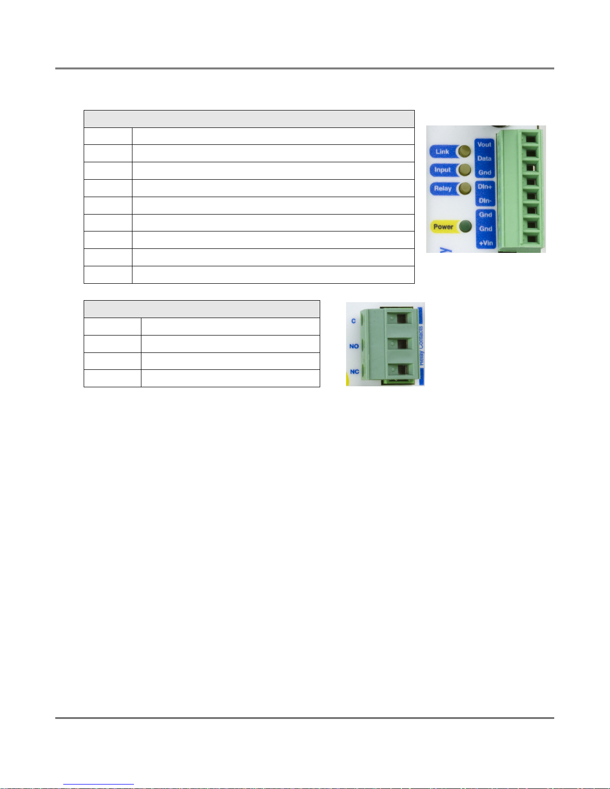
The XW-210 has an 8-position removable screw terminal connector for power, input and sensor connections. A
separate 3-pin connector provides connections to the internal relay.
8-Pin Connector
Terminal Description
Vout
Data
Gnd
Din+
Din-
Gnd
Gnd
+Vin
+5V output to power 1-wire sensor(s), 50mA max
Serial data line for 1-wire sensor(s)
Gnd output for 1-wire sensor(s)
Digital Input + The positive side of the optically-isolated input.
Digital Input - The negative side of the optically-isolated input.
- Power Input (GND)
- Power input (GND)
+9 to 28VDC power input
3-Pin Connector
Terminal Description
C
NO
NC
Relay COMMON
Relay NORMALLY OPEN
Relay NORMALLY CLOSED
Xytronix Research & Design, Inc. Page 7
Page 8
Introduction XW-210 WiFi™ Users Manual
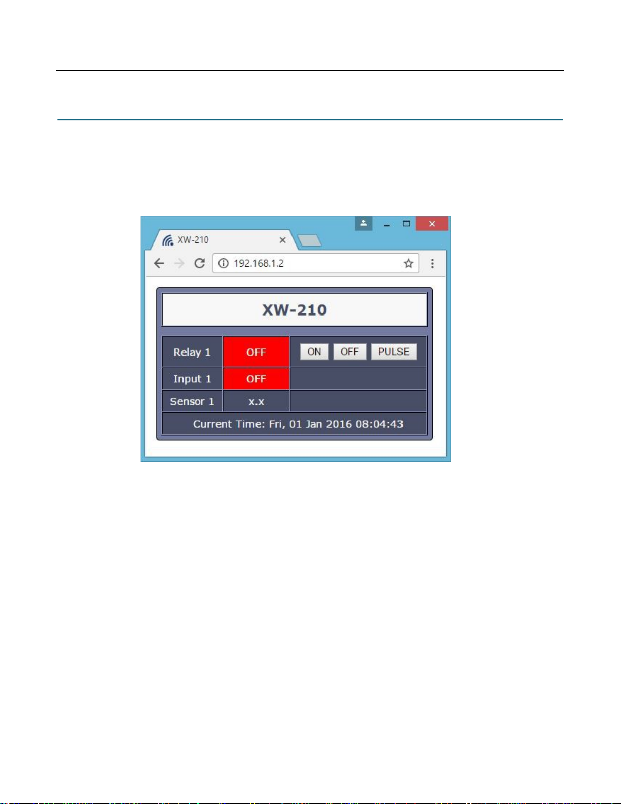
1.6 Accessing the XW-210 using a Web Browser
The XW-210 has a built-in web server that provides simple web pages that can be accessed directly
using a standard web browser. This allows users to access the unit with NO SPECIAL SOFTWARE
installed on their computer. This is ideal for applications that require a quick, simple solution that does
not need to be accessible to more than a few people. This configuration is simple to setup, simple to use,
and can be accessed from just about any computer or smart phone.
Page 8 Xytronix Research & Design, Inc.
Page 9
XW-210 WiFi™ Users Manual
Section 2: Installation and Connections
Installation consists of mounting the XW-210 and connecting it to a power source. See Section 3:
Provisioning for instructions on commissioning the XW-210 such that it can recognize and connect to
your Wi-Fi access point.
2.1 Installation Guidelines
• This unit must be installed by qualified personnel.
• This unit must not be installed in unprotected outdoor locations.
• This unit must not be used for medical, life saving purposes, or for any purpose where its failure
could cause serious injury or the loss of life.
• This unit must not be used in any way where its function or failure could cause significant loss or
property damage.
• Do not use to directly control motors or other actuators not equipped with limit switches or other
safeguards to protect from equipment or wiring failures.
• The XW-210 should be located in a clean, dry location where it is protected from the elements.
Ventilation is recommended for installations where ambient air temperatures are expected to be
high. See Appendix E: Mechanical Information for additional mechanical details.
• The 1-wire temperature probes are water resistant and can be used in outdoor applications
however, they are not suitable for immersion or use in pressure vessels. For immersion and
other demanding applications use a thermowell to protect the sensor.
2.1.1 Wall Mounting
Mount the XW-210 to a wall by using two #8 screws. Attach the screws to the wall vertically spaced
exactly 2.5 inches apart. The head of the screw should be about 1/10 inch away from the wall.
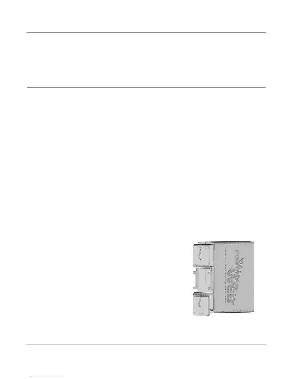
2.1.2 DIN-Rail Mounting
The XW-210 can be mounted to a standard (35mm by 7.55mm) DINRail. Attach the XW-210 to the DIN-Rail by hooking the top hook on
the back of the enclosure to the DIN-Rail and then snap the bottom
hook into place. To remove the XW-210 from the DIN-Rail, use a flathead screwdriver. Insert the screw driver into the notch in the release
tab and pry against the enclosure to release the bottom hook.
Xytronix Research & Design, Inc. Page 9
Page 10

Installation and Connections XW-210 WiFi™ Users Manual
2.2 Making Connections
CAUTION: Make sure the power is shut off before making connections
CAUTION: This unit should be installed by a qualified technician.
CAUTION: Miswiring or misconfiguration could cause permanent damage to the XW-210, the
equipment to which it is connected, or both.
A removable terminal connector is provided for making the power connections. To help protect the XW210 from mechanical stress remove the terminal connector before making the connections.
1. Make sure power is turned off.
2. Remove the terminal connector from the XW-210 and make wiring connections to the terminals.
This technique avoids stressing the internal components while torquing the screws.
3. Reconnect the terminal connector.
4. Apply power.
It is recommended that any load (device to be controlled) not be connected until after the XW-210 has
been configured and tested. By doing this, wiring and configuration mistakes will not cause the load to
turn on unexpectedly. Make certain the wires are properly inserted into to the terminals and that the
screws are tight.
Relay Connector Specifications:
Type: 3-position, removable, 7.62 mm (.30”) pitch
Connection wire: Use wire rated for 75ºC (min) for connections to the relay terminal block
Stripping Length: 7mm
Connection capacity: 2.5mm2 stranded, 2.5mm2 solid
Conductor minimum: 30AWG (UL/CUL)
Conductor maximum: 12 AWG (UL/CUL)
Conductor Type: Copper
Tightening torque: 0.5 Nm (min), 0.6 Nm (max)
2.2.1 Power Supply Connections
The XW-210 requires power for its internal logic circuits. Connect a 9-28 VDC power supply to the +Vin
and GND terminals. A regulated power supply is recommended, such as a wall-mount AC-DC adapter.
Verify that the adapter is rated for the operating current of the XW-210 (See Appendix A: Specifications
for the current requirements.) Multiple XW-210 units may be connected to a single power supply by
connecting the power supply input terminals in parallel. The power supply must have a high enough
current rating to power all units connected. If the XW-210 is powered with a solar panel, the system must
include a solar charge controller and a battery.
Page 10 Xytronix Research & Design, Inc.
Page 11

XW-210 WiFi™ Users Manual
2.2.2 Antenna Connection
The XW-210 comes with an approved 2.4GHz omnidirectional antenna for use with WLAN devices using
WiFi (802.11b/g/n). The omnidirectional pattern is suitable for point-to-multipoint broadcasting in all
directions. Connect the antenna to the Reverse SMA connector on the faceplate. Do not operate the XW210 without the antenna connected.
The omnidirectional antenna radiates RF signals in all directions in one plane with a pattern shaped
somewhat like a doughnut or torus. The radiated power decreases above or below the plane, dropping to
zero on the antenna's axis. Orient the antenna vertically so the antenna will radiate in all horizontal
directions and so little radio energy is aimed into the sky or down toward the earth and lost.
This device has been approved to operate with an antenna (provided) with the maximum permissible
gain specified in the specification (Appendix A: Specifications). Antenna types not included in this
specification, having a gain greater than the maximum gain indicated for that type, are strictly prohibited
for use with this device.
The antenna used for this transmitter must be installed to provide a separation distance of at least 20 cm
from all persons and must not be co-located or operating in conjunction with any other antenna or
transmitter except in accordance with FCC multi-transmitter product guidelines.
Xytronix Research & Design, Inc. Page 11
Page 12
Installation and Connections XW-210 WiFi™ Users Manual
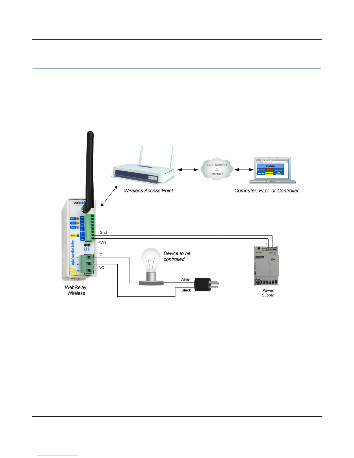
2.3 Relay Connections (Control a device over an IP network)
The illustration below shows a simple example of using the relay in the XW-210 to control a device over
an IP network. The device to be controlled is wired in series with the relay contacts.
Note: The circuit must include a fuse or circuit breaker to provide over-current protection.
Page 12 Xytronix Research & Design, Inc.
Page 13
XW-210 WiFi™ Users Manual
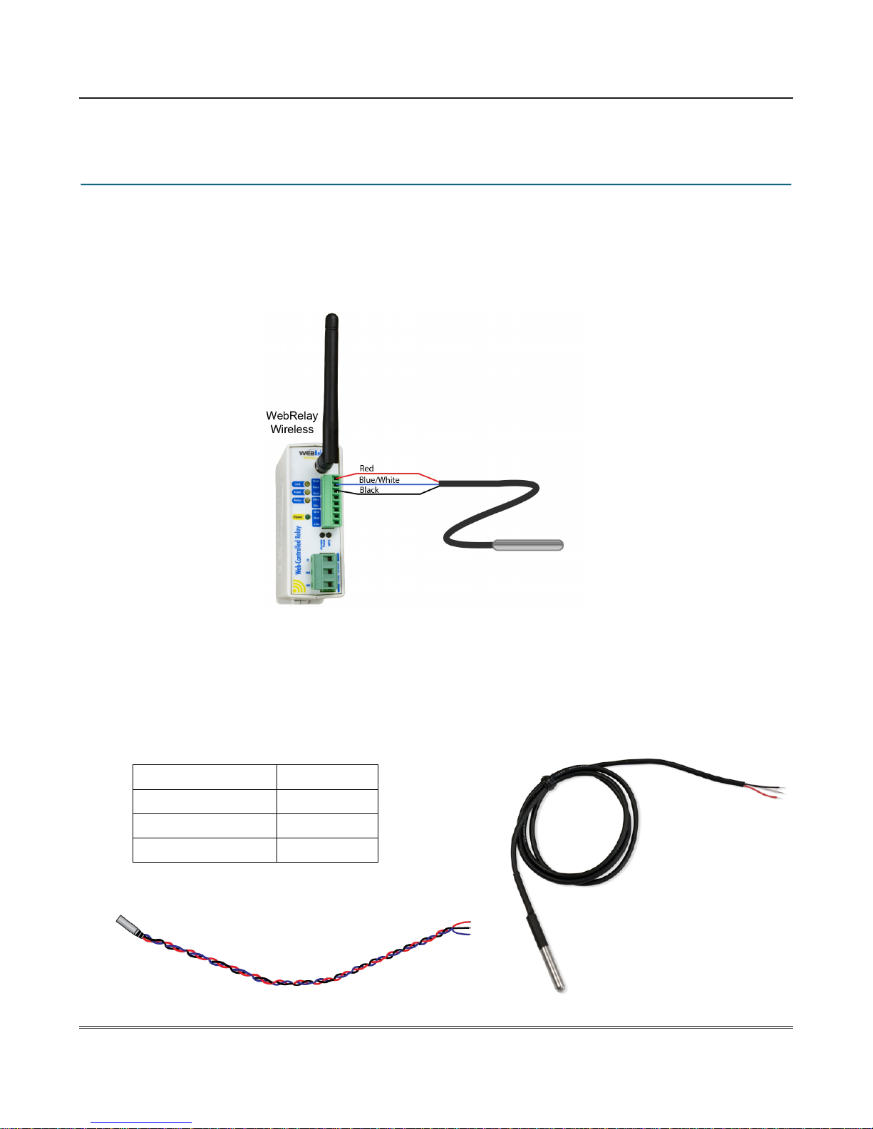
2.4 1-Wire Sensor Connections
The XW-210 has a “1-wire” port which supports up to four digital temperature or other Xytronix 1-wire
sensors. The sensors share the same three connections for communications and power (+5V, Ground,
Data). Every sensor on the bus is assigned a unique serial number when it is manufactured. That
number is used to address the sensor during communication.
The digital temperature sensors are interchangeable and require no calibration. The sensors accuracy is
+/-0.5°C (-10°C to +85°C). The temperature sensor is available in several configurations. The
encapsulated version has a stainless steel probe and can be used in outdoor applications however, the
probe is not suitable for immersion or use in pressure vessels. For immersion and other demanding
applications use a thermowell to protect the sensor. The basic sensor (non-encapsulated) must used in
protected locations. The temperature sensors have three wires as shown below.
Sensor Wire Color Connection
Red +5V
Black Gnd
Blue, White, Yellow Data
Xytronix Research & Design, Inc. Page 13
Page 14
Installation and Connections XW-210 WiFi™ Users Manual
Multiple sensors can be connected in two ways: directly connected (star topology) or “daisy chained”
(linear topology). Many factors can determine the maximum length of the cable, including the sensor
network topology, the type of cable used, the number of sensors and ambient electromagnetic noise.
Combined cable lengths to all sensors of 600 ft using Cat 5e cable have been successful. However, due
to the uniqueness of installation environments, results may vary. Please test in the desired environment
before making a permanent installation.
The following are general recommendations that will maximize sensor runs and minimize problems.
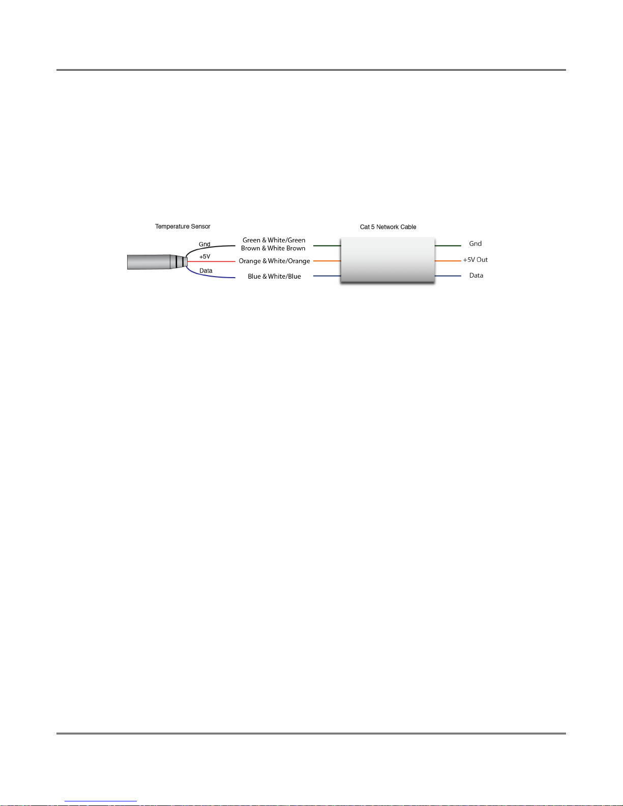
Cat 5 and Cat 5e network cable has proven to be an effective and low-cost solution for long runs. Other
cable types can be used, but cable capacitance generally limits the length. The illustration shows the
recommended connection using Cat 5 network cable. Connect all unused conductors to ground.
Recommended connections using Cat 5 cable
A linear (daisy chain) topology will minimize signal reflections, providing a more reliable connection and
will allow longer cable length than a star topology.
The 1-wire bus is "single-ended" and has no intrinsic noise protection. It is susceptible to interference if
the cable is routed near power lines, fluorescent fixtures, motors or other noise sources. Keep the cable
wiring short and avoid routing it near other electrical equipment.
Page 14 Xytronix Research & Design, Inc.
Page 15

XW-210 WiFi™ Users Manual
2.5 Digital Input Connections
The XW-210 has an optically-isolated digital input which can be used to control the relay and/or a remote
relay (over the network), or simply to monitor the state of a device. To use this input, connect a DC
control voltage directly to the input, and customize the input function using the XW-210 configuration
pages.
2.5.1 DC Input
The digital input is connected internally through a current-limiting resistor directly to a photo-coupler
circuit. No external resistor is necessary as long as the input signal is within the proper range (See
Appendix A: Specifications). A DC voltage can be reduced with an external resistor of the appropriate
value and power rating to reduce the input current.
The digital input has an internal 3K ohm resistor. The forward voltage drop of the photo-coupler is
approximately 1.2V and works well with an input current of 9mA. Use the following formula to determine
the resistor value needed for other voltage ranges:
R =((Vin-1.2)/0.009)-3000
Where:
• R = External resistor value required
• Vin = Desired input voltage
• 1.2V = forward voltage drop of the LED in the photo coupler
• .009A = workable LED current
• 3000 ohm = Internal resistor
For example:
To connect a 48VDC signal voltage to the XW-210:
R = ((48-1.2)/0.009)-3000 = 2200 ohms
Check the power dissipated by the resistor:
P = I x I x R, The resistor must be at least .009 x .009 x 2200 = 0.18 Watts, so use a 1/2
Watt resistor.
Xytronix Research & Design, Inc. Page 15
Page 16
Installation and Connections XW-210 WiFi™ Users Manual
2.5.2 Switch Closure Connections
The XW-210 can sense the state of a switch closure sensor. Sensors with switch closure outputs include
push buttons, magnetic door alarm switches, micro-switches, or any device which has a relay, switch
closure or open collector output. The XW-210 can be configured for the alarm to be active when the
switch is either open or closed.
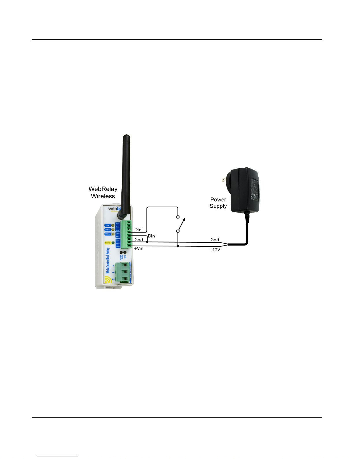
The illustration below shows an example of using the XW-210 to monitor the status of a gate or door
over an IP network. The status of the device is detected with a switch. These types of sensors are called
“dry contacts” in that the sensor output is a bare switch with no power source. In this example the voltage
source for the switch is provided via the power supply for the XW-210.
Page 16 Xytronix Research & Design, Inc.
Page 17
XW-210 WiFi™ Users Manual
2.5.3 Water Leak Sensor Connections
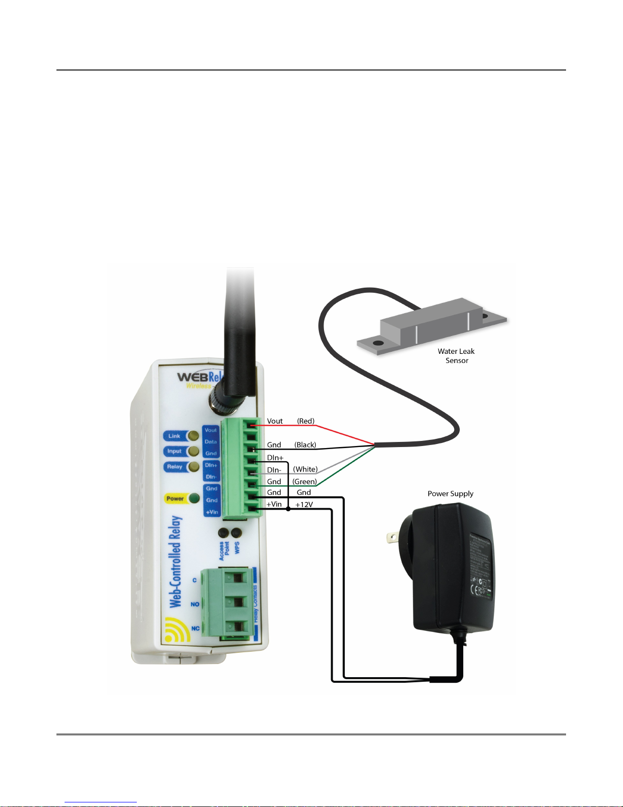
A GRI-2605 water leak detector can be directly connected to the XW-210. The sensor detects the
presence of water or other conductive liquids. The sensor has 4-wires which are connected as shown
below. The GRI-2605 has an internal relay whose contacts (green & white wires) are closed when the
sensor is dry. When the sensor is dry the digital input will be On. When water is detected the relay
contacts open and the digital input will be Off. With the connections shown the sensor is a closed loop
“supervised” alarm circuit such that if a wire is disconnected or the sensor fails, an alarm will be
generated. The XW-210 can be programmed to activate it's relay, activate a relay at a remote location or
send an e-mail warning when a water leak is detected. The GRI-2605 is not recommended for
submerged applications or prolonged exposure to water. After installation test the sensor with a damp
sponge or wet towel.
Xytronix Research & Design, Inc. Page 17
Page 18
Installation and Connections XW-210 WiFi™ Users Manual
2.5.4 AC Input Connections
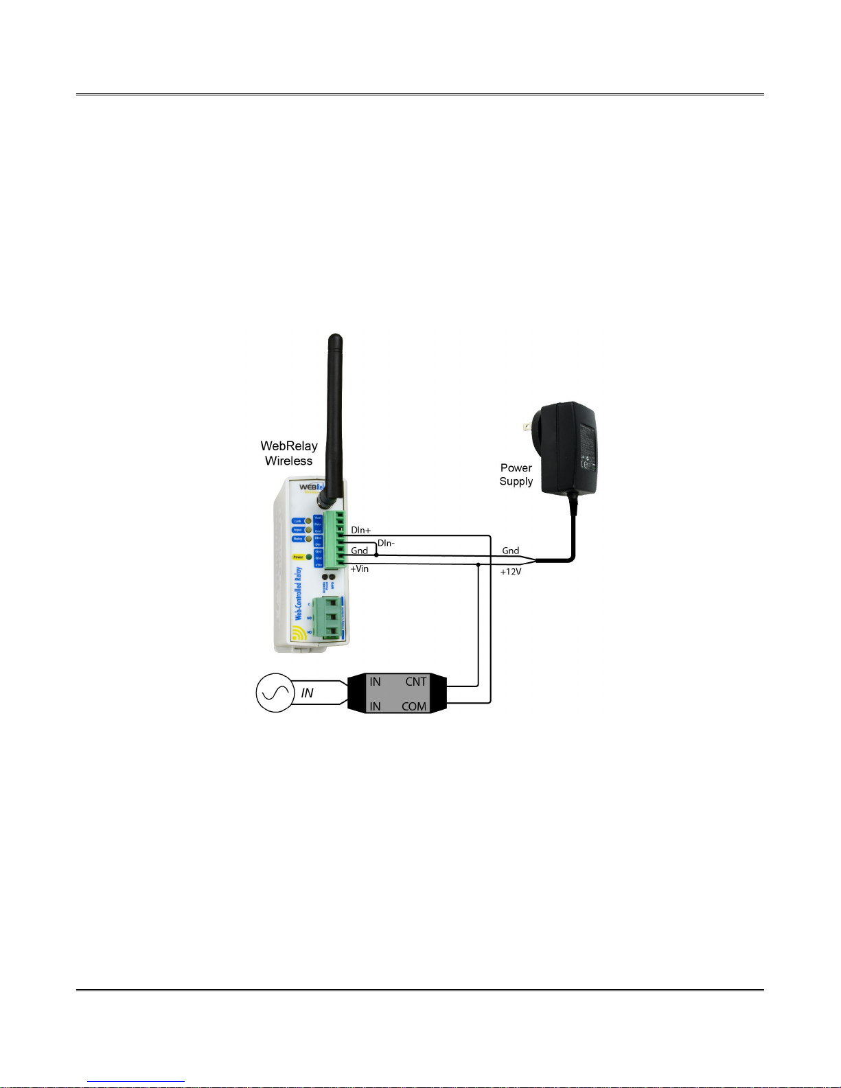
If an AC signal voltage needs to be detected, use a signal conditioner to convert the AC signal to a DC
voltage within the input range. An AC signal conditioner can be made using a diode (or bridge rectifier)
and a capacitor. Prepackaged signal converters are available as accessories at industrial automation
distributors. A simple voltage converter module (RedLion VCM10000 or VCM20000) is shown below.
These are available in two input voltage ranges that cover the spectrum from 4-270VAC/DC. These
devices have a MOSFET output (solid state DC contact closure) which is compatible with the XW-210
input. The converter module accepts AC (50/60 Hz) or DC voltages with an input pulse rate up to 30 Hz.
The converter provides isolation between the input and output using an opto-isolator. You must provide a
voltage source for the converter circuit as shown in the example below:
Page 18 Xytronix Research & Design, Inc.
Page 19

XW-210 WiFi™ Users Manual
Section 3: Provisioning
After making the sensor connections and providing power, you must provision the XW-210 for use on
your wireless network. The goal is to configure the XW-210 such that it can recognize and attach to your
Wi-Fi access point. There are two methods for doing this:
3.1 Access Point
By default, the XW-210 comes up as a wireless access point when powered for the first time. Pressing
the "access point" push button any time also activates the access point mode. It isn't really an access
point because it will not provide internet connectivity to your computer or smart phone, but it will appear
as an access point meaning that your computer or smart phone will detect it as an access point and
display it as such. When acting as an access point, the XW-210 broadcasts an SSID of “XW210XXXXXX” where XXXXXX are the last six digits of its MAC address.
With your wireless device (laptop computer or smart phone) scan for, and attach to the XW210 wireless
network. Next, access the web server in the XW-210 using a web browser. To access the setup pages,
enter the following URL in the address bar of your web browser:
http://192.168.1.2/setup.html
After the page is requested, a password prompt will appear. Enter the username and password. The
username is admin and the password is webrelay (password is case sensitive). The next chapter
explains each of the setup tabs and screens. Use the WiFi Networks tab for making the proper settings
to allow the XW-210 to connect to your access point.
Notes About Access Point Mode:
• As an Access Point the XW-210 functions independently of other wireless networks. It
broadcasts beacons and services WiFi packet requests. In this mode, your computer or smartphone is connected directly with the XW-210 on a private network and is NOT using another
WiFi network. Typically you would use this for configuration and not for normal operation.
• The XW-210 has no hardware “restore defaults” button, to prevent the installer from being locked
out, the default username (admin) and password (webrelay) always work in the access point
mode, even if the password is changed. If the password has changed via the Password tab, both
the new password and the webrelay password will work. Additionally, the IP address and HTTP
port will temporarily revert to the default values shown above when in the access point mode.
• Only one client (computer or smart-phone) can be connected to XW-210 at a time.
• SSID and password cannot be customized (once again this mode is intended for configuration
only).
• Access point is unsecured and open.
Xytronix Research & Design, Inc. Page 19
Page 20

Provisioning XW-210 WiFi™ Users Manual
3.2 WPS (Wi-Fi Protected Setup)
The WPS Push button method, provides a simple method for attaching the XW-210 to a wireless
network without needing to use any setup pages. Although using this method to connect the XW-210 to
the network is simple, you will not be able to access the XW-210 web server unless you know the IP
address that was assigned by the DHCP sever (router) or unless mDNS services are available on your
device. For this reason, it is recommended that you use this method of configuration only when the XW210 units have been pre-configured to operate in a non-web-server mode or when you have full access
to the DHCP server so you can obtain the IP address that was assigned.
To begin, press the WPS button on your wireless router or access-point. You will generally have about
two minutes to connect wireless devices to the network with WPS. Now press the “WPS” push button on
your XW-210. After a few seconds, the XW-210 should register itself with the router or access-point. If
WPS fails, the XW-210 will automatically enter the access point mode.
The XW-210 will use DHCP to obtain an IP address after a successful WPS association. Additionally, the
connection information is also broadcast using mDNS. If you need to access the XW-210 using its
internal web server you will need to obtain the IP address that was assigned to the XW-210 through your
DHCP server or router. Alternatively, if using an mDNS capable device, it may be accessed by entering
the following into the address bar of your web browser:
http://xw-210.local/setup.html
Page 20 Xytronix Research & Design, Inc.
Page 21

XW-210 WiFi™ Users Manual
3.3 Application Examples
The XW-210 can be configured for many different applications. Two general examples are described
below:
3.3.1 Warehouse Temperature Example with no Access Point
You wish to monitor the temperature of a warehouse with a your smart phone. You don't have a WiFi
access point.
Mount an XW-210 inside the warehouse. Power it with a DC wall adapter. If no network profiles have
been configured, the XW-210 will automatically enter the access point mode and you can access the
XW-210 directly with a computer or smart device with a wireless connection. If the XW-210 has been
previously configured for other uses, press the Access Point button. Scan for, and attach to the XW210XXXXXX wireless network. Access the setup pages with the following URL:
http://192.168.1.2/setup.html
Click the Restore Defaults button on the Main setup page. Scan for and reattach to the XW210-XXXXXX
network again. The XW-210 is workable for this application with the default settings, no further settings
are needed. Note, only one device can be connected to the XW-210 at a time when it is in the Access
Point mode. The XW-210 will continue to broadcast an SSID and you can connect to the XW-210
anytime with your smart phone and view the temperature on the Control page (http://192.168.1.2). Since
the XW-210 is not connected to the internet, you must be within 250 feet or so with your smart phone to
receive the WiFi signal from the XW-210. The XW-210 cannot send emails or remote relay commands
because it is not connected to the internet. Be aware that the Access Point is unsecured and open and
the default passwords cannot be changed.
3.3.2 Warehouse Temperature Example with an Access Point
You wish to monitor the temperature of a warehouse with your smart phone or office computer. You have
a WiFi access point in the warehouse. The HTTP web server is enabled to provide continuous access to
the control page.
Mount an XW-210 inside the warehouse. Power it with a DC wall adapter.
First, the XW-210 must be configured to access your WiFi network. If no network profiles have been
configured, the XW-210 will automatically enter the access point mode and you can access the XW-210
directly with a computer or smart device with a wireless connection. Access the setup pages with the
following URL: http://192.168.1.2/setup.html
For this application configure the XW-210 to connect to your wireless network. Navigate to the WiFi
Networks tab and fill in the appropriate settings for your WiFi network. Obtain the IP address from your
network administrator. Press the submit button at the bottom of the page.
Once all the appropriate settings have been applied, click on the Reboot button. The XW-210 will
connect to, and remain connected to your access point. The XW-210 will now be accessible from the IP
address configured on the WiFi Networks tab. The XW-210 will no longer broadcast an SSID. You can
access the control page any time to monitor the warehouse temperature by entering the IP address that
was assigned to the device in the address bar of your web browser. Since your access point is connected
to the internet, you can monitor the temperature from any computer in the building. If the XW-210 does
not connect within a period of time, press the Access Point Button and repeat the above steps to verify
the network settings.
Xytronix Research & Design, Inc. Page 21
Page 22
Web Server XW-210 WiFi™ Users Manual
Section 4: Web Server
The internal web server presents two classes of web pages; Setup pages and Control pages. Setup
pages are used by an installer to provision and configure the XW-210. The Control page allows the relay
to be controlled and displays temperature and digital input status information.
To access the control page, enter the following URL in the address bar of a web browser:
http://192.168.1.2
To access the setup pages, enter the following URL in the address bar of a web browser:
http://192.168.1.2/setup.html
Note that if you are accessing the unit as an access point the above IP address will work even if you
have changed the IP address in the setup pages. If you are accessing the unit through the network after
it has been configured you will use the IP address that was assigned to the device.
If the XW-210 has been added to a network using WPS, it will use DHCP and you will need to use the IP
address assigned to it. This can be found in the DHCP server, or by using mDNS. The mDNS name is:
http://xw-210.local/
When using the setup pages, you must click the Submit button at the bottom of a page if you have made
changes to a setting on the page.
4.1 Main Tab
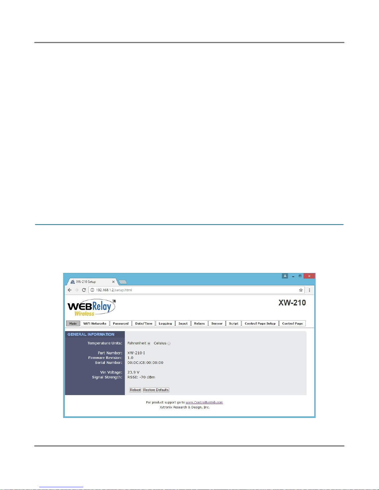
This is the initial page that is displayed when setup.html is entered in the address bar of the browser.
It displays model and serial number information, and has navigation tabs which allow access to the
configuration and setup settings. Each of the configuration settings are described in the following
sections.
Page 22 Xytronix Research & Design, Inc.
Page 23

XW-210 WiFi™ Users Manual
Temperature Units:
This global setting selects temperature units of either Fahrenheit and Celsius. All settings entered and
displayed on subsequent pages will be in the units selected.
Part Number:
This is the full model number of the XW-210.
Firmware Revision:
This is the current revision of the internal software.
Serial Number:
This is the serial number of the XW-210. The serial number is also the MAC address of the unit.
Vin Voltage:
This field shows the input voltage on the +Vin and Gnd terminals from your power supply.
Signal Strength:
This indicates the current receive Wi-Fi signal strength. The more negative the number the less signal is
being received. -30dBm is a strong signal, and -90dBm is a very weak signal.
Reboot:
After showing a confirmation message, this button will send a command to reboot the device.
Restore Defaults:
After showing a confirmation message, this button will erase all user settings and return the module to its
factory defaults.
Xytronix Research & Design, Inc. Page 23
Page 24
Web Server XW-210 WiFi™ Users Manual
4.2 WiFi Networks Tab
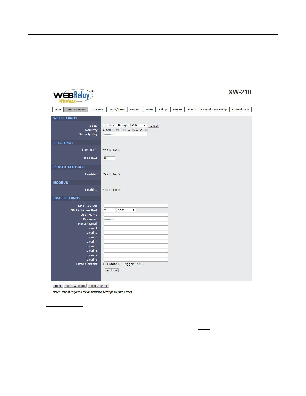
As a Wi-Fi client device, the XW-210 attempts to automatically connect to configured Wi-Fi access
points. The settings on this page are used to configure this process.
WiFi SETTINGS
SSID:
The SSID (Service Set Identifier) is the name of the Wi-Fi network you wish the XW-210 to connect to.
Click the Refresh button to make a fresh scan of available networks. Note: The Refresh button is inactive
if the XW-210 itself is an access point. The drop down list shows each Wi-Fi network discovered together
with its signal strength.
Security:
Page 24 Xytronix Research & Design, Inc.
Page 25

XW-210 WiFi™ Users Manual
Type of authentication used by the access point for connections.
Security Key:
Enter the security key or password for the WiFi network to connect to (hidden when not applicable.)
IP SETTINGS
Use DHCP:
This option allows DHCP to be enabled or disabled. If this option is set to Yes, the XW-210 will wait for
an IP address from a DHCP server each time it is powered. The default setting is No (this is
recommended for most installations). If DHCP is set to Yes, the Network page must be submitted and
the XW-210 must be rebooted before an IP address will be assigned. Once the XW-210 is assigned an
IP address by the DHCP, the new IP address can be found through the clients list kept by the DHCP
server. For most instances, this is found on the local gateway or router. Alternatively, the device will
broadcast its information via mDNS.
Brief Notes About DHCP
All devices on an IP network require an IP address. This is a unique address that identifies each device
on the network. DHCP (Dynamic Host Control Protocol) is a mechanism that automatically assigns an IP
address to a computer (or other devices) when it is connected to a network. This eliminates the need to
manually enter the IP address. When a computer is connected to the network, another device on the
network called a DHCP server detects the presence of the computer and dynamically assigns the IP
address to that computer. On many small networks, the DHCP server is built into the router.
DHCP works well for "client" devices such as computers, but is not ideal for servers. This is because
servers usually don't initiate communications with other devices, but rather they wait for a request from
"clients." To make this request, the client must know the IP address of the server. If a server gets its IP
address dynamically, the IP address may not always be the same so client devices may not be able to
find the server. For this reason, servers usually use an IP address that is fixed and does not change. The
XW-210 is a server and manual IP address assignment is usually recommended.
IP Address:
Enter the IP address for the XW-210 in this field. The IP address is specific to the network where the
XW-210 will be installed and is obtained from the network administrator. The default setting for this field
is 192.168.1.2.
Subnet Mask:
The subnet mask defines the size of the local network. This can be obtained from the network
administrator. For additional information about sub-netting and IP networking, many tutorials are
available on the Internet. The default setting for this field is 255.255.255.0.
Gateway:
This specifies the IP address of the gateway router. This can be obtained from your network
administrator. The default setting for this field is 192.168.1.1.
DNS Server:
The IP address of the DNS server is specified here. When DNS services are required, this is the address
that will be used. The default setting for this field is 192.168.1.1. An alternate DNS server is not
supported.
HTTP Port:
The TCP port used for HTTP communications with the XW-210 can be customized here. The default
setting for this field is 80, which is the standard HTTP port. It is recommended that the port be left
unchanged unless the user has an understanding of TCP/IP and ports.
Xytronix Research & Design, Inc. Page 25
Page 26
Web Server XW-210 WiFi™ Users Manual
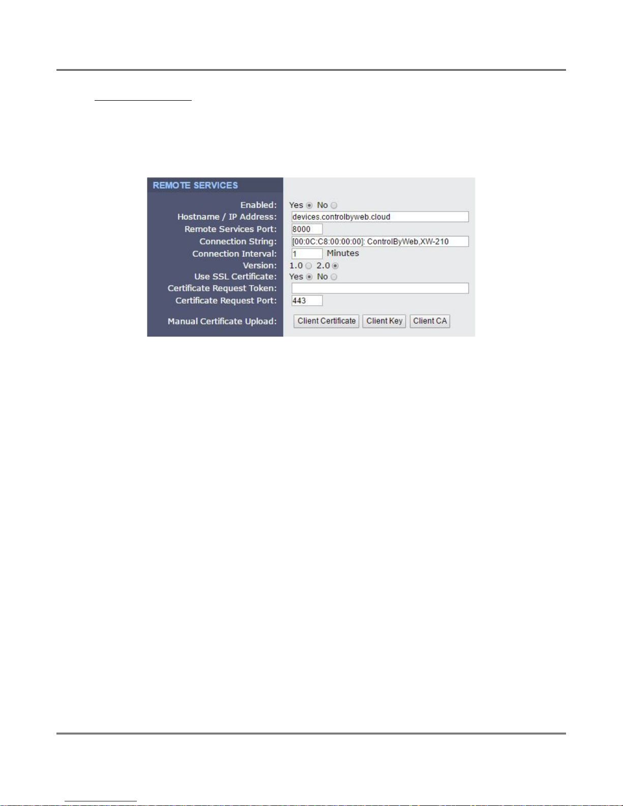
REMOTE SERVICES
If Remote Services is enabled, the XW-210 will immediately attempt to make a connection with the
remote server (power cycle not required). Once a connection is established, the connection will remain
until it is disconnected by the remote server. If the connection is lost, it will automatically reconnect
according to the Connection Interval.
Hostname / IP Address:
The URL or IP address of the server you wish to send (push) data to. If the IP address is specified, enter
it in this format aaa.bbb.ccc.ddd. For numbers that are less than 100, preceding zeros should not be
included (for example, enter 80 rather than 080). This field can be up to 40 characters long and has no
default setting.
Remote Services Port:
The TCP port used for communications with the remote server. This can be set within the range of 1-
65535. The default setting for this field is 8000.
Connection String:
This text is sent to the Remote Services server when the connection is established. This string should
include any information required by the server at connection. For example, it may include an ID number,
customer number, password, etc. The format is entirely dependent upon the server requirements. This
field can be up to 80 characters long. Default text is provided only as an example placeholder. The
default text is [<Serial Number>]:ControlByWeb,XW-210.
Connection Interval:
This field specifies the periodic interval in which XW-210 attempts to connect to the remote server, or if
XW-210 is already connected, it is the interval in which XW-210 sends the connection string. The default
setting is 1 minute.
Version
This field specifies the version of the remote services' protocol to use. Version 1 of the protocol sends
the connection string after successfully connecting to the remote server and then periodically per the
connection interval specified. Version 2 of the protocol sends the connection string in addition to the MAC
address, connection interval, model number and then immediately sends the state.xml file of the device.
Version 2 of the protocol requires the remote server to reply to the connection string with a 3 byte packet
Page 26 Xytronix Research & Design, Inc.
Page 27

XW-210 WiFi™ Users Manual
containing the text “ACK”. If the “ACK” is not received within 10 seconds of sending the connection
string, the XW-210 will close the connection. Version 2 continues to send the connection string and the
state.xml file periodically per the connection interval specified.
Use SSL Certificate
This option enables encryption of the remote services' connection with the remote services' server as
well as authentication of the XW-210 to the server by a client certificate and key. Custom certificates and
keys can be loaded into the XW-210 for this purpose. (See Remote Services at the end of this section for
more information.)
By default, the XW-210 does not come with any SSL certificates already installed. The certificates will
need to be installed either manually by uploading the files or automatically with a token. The SSL
certificates must be in the PEM format.
Certificate Request Token
When the XW-210 has a valid Certificate Request Token entered, it will automatically attempt to request
and download its Client Certificate, Key, and CA. Once successful, the token will be erased and the XW210 will stop its requests. (See Remote Services at the end of this section for more information.)
Certificate Request Port
The certificate server is a server that has been configured to deliver the Client Certificate, Key, and CA
when requested by the XW-210. For the XW-210 to request a Certificate, Key, and CA from the
certificate server, it must have a previously issued Certificate Request Token. This field specifies what
port the Certificate Server listens on. The server is found at the same host name as the remote services'
server. (See Remote Services at the end of this section for more information.)
Manual Certificate Upload
Client Certificate
A client certificate is used with custom remote services' servers for device authentication. To upload a
custom client certificate to the XW-210, click the Browse button, find the PEM formatted certificate file,
and select Submit.
Client Key
A client key is used with custom remote services' servers for device authentication. The key that is
uploaded must be the correct key associated with the Client Certificate. Care should be taken with where
this client key is stored as it is meant only to be known to the XW-210. To upload a custom client key to
the XW-210, click the Browse button, find the PEM formatted file, and select Submit.
Client CA
A CA (Certificate Authority) is used by the XW-210 to verify the authenticity of the remote services' server
it is connecting to. It is important to note that this CA does not need to be the CA that signed the Client
Certificate used by the XW-210. Rather the CA needs to be the one used to sign the certificate used by
the remote services server. To upload a custom CA to the XW-210, click the Browse button, find the PEM
formatted file, and select Submit.
Remote Services Notes: Remote services initiates an outgoing connection to a server at a remote
location. This can be used in an environment where a web server on the Internet provides a custom web
page to XW-210 and other ControlByWeb products. Users access the XW-210 through the web server
rather than communicating directly with it. This method is sometimes referred to as “web services” and
allows programmers to create powerful, custom web pages to multiple devices using the web
programming languages of their choice.
Remote services initiates the connection to the external web server (rather than the web server initiating
communications to the XW-210). This has two main benefits. First, the web server does not need to
Xytronix Research & Design, Inc. Page 27
Page 28
Web Server XW-210 WiFi™ Users Manual
know the IP address of XW-210. This means that XW-210 can get its IP address dynamically from a
DHCP server, simplifying the installation. Second, since the connection from XW-210 is outgoing, rather
than incoming, the local router on the network where XW-210 resides doesn't need to be configured to
forward sockets. This simplifies the installation. Since the router configuration is not modified, the risk of
compromising security on the local network is eliminated.
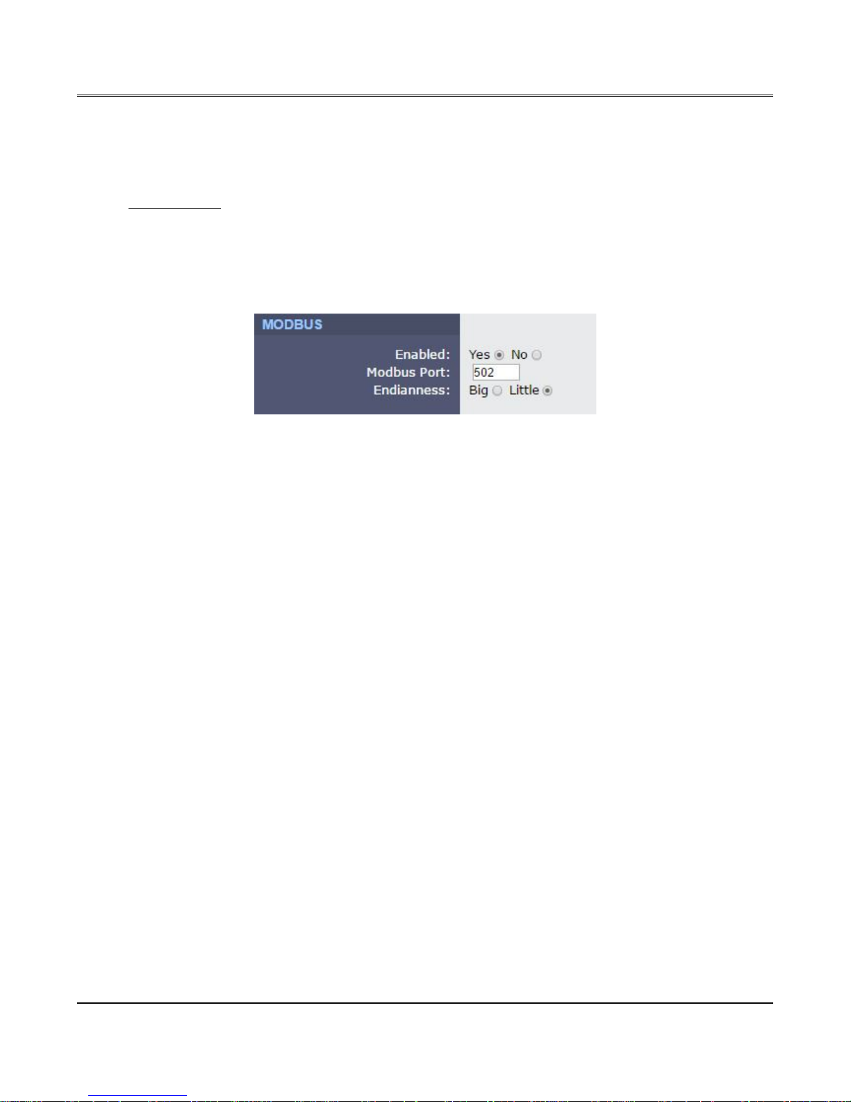
MODBUS/TCP
XW-210 can support Modbus/TCP. Modbus is a messaging structure protocol used in industrial
manufacturing control and automation. It is an open protocol and offers interoperability with software and
devices from other manufacturers. (See Section 6.6: Modbus Operation.)
Note: Modbus communications are disabled whenever the Control Password is enabled.
Modbus Port:
This specifies the port used for Modbus/TCP communications with XW-210. By default this is set to port
502 which is the standard Modbus port. It can be set within the range of 1 to 65535.
Endianness:
32-bit data is treated as two individual 16-bit words using IEEE 754 floating point format. Floating point
format is used for sensor data and pulse counter as well as for setting output pulse duration.
When the XW-210 is set for big-endian architecture, the most significant 16-bit word (big end) is sent
first. Otherwise the XW-210 will use little-endian architecture, and the least significant word (little end) is
sent first. The default setting for this is little-endian.
For example, in little-endian format, a 32-bit floating point number represented by '1234 ABCD' is sent as
'ABCD1234
Page 28 Xytronix Research & Design, Inc.
Page 29

XW-210 WiFi™ Users Manual
EMAIL SETTINGS
An email can be sent when a temperature alarm or digital event occur. A BASIC script can also initiate an
email message. This section is used to configure the email settings for up to eight email addresses. The
same message is sent to each email address. For email notification to work, the XW-210 must have a
properly configured network connection and a SMTP server must be defined. Emails only work if the
XW-210 is connected to an access point and can send messages on the internet.
Email triggers can be generated within a BASIC script (See Section 6.7: BASIC Scripts), or can be
explicitly defined for each Sensor, Input, and Relay. The email options and recipients for each Sensor,
Input, and Relay are configured separately. For each Sensor, Input, and Relay select the Email Option
and the check box for the desired email recipient.
SMTP Server:
The SMTP mail server host name.
SMTP Server Port:
The port number of the SMTP mail server. This is generally 25 for non encrypted SMTP servers. If using
SSL/TLS, this port number is generally 465.
SSL:
Check this check box if the server and port you have configured is expecting a SSL connection.
User Name:
Email user name (if required).
Password:
If the SMTP mail server requires authentication, the password must be entered here. There is no default
setting for this field.
Return Email:
XW-210 will not receive email messages, but when XW-210 sends email messages, it must include a
return email address. This field is used to specify the return email address. Note that although XW-210
will send email messages with any email address specified in this field, some email filters (spam filters)
will not allow messages through that include an invalid email address. There is no default setting for this
field.
Email 1:
When an alert occurs an email message is sent to this address.
Email 2:
When an alert occurs an email message is sent to this address.
Email 3:
When an alert occurs an email message is sent to this address.
Email 4:
When an alert occurs an email message is sent to this address.
Email 5:
When an alert occurs an email message is sent to this address.
Email 6:
When an alert occurs an email message is sent to this address.
Xytronix Research & Design, Inc. Page 29
Page 30

Web Server XW-210 WiFi™ Users Manual
Email 7:
When an alert occurs an email message is sent to this address.
Email 8:
When an alert occurs an email message is sent to this address.
Email Content:
When “Full State” is selected, all visible fields in the control page will be included in the email message to
be sent out. “Trigger Only” only includes the status of the I/O that triggered the email alert to be sent.
Short messages can be easier to read when sent to cell phones as text messages.
Test Email:
Pressing this button will submit any changes to the email settings and trigger an alert email to be sent to
the configured email addresses. The result of the test email will be displayed next to this button once the
attempt has been completed. The Test Email button is disabled if the device is in the Access-point mode.
The following are typical responses you may see along with a description of what they mean:
• Error initiating communications: Did not receive the expected HELO from SMTP server. Ensure
you are using the proper port and host/IP settings.
• Error with EHLO: Error sending or error receiving proper response to the SMTP EHLO
command. Server may be unavailable or port and IP address settings are not correct.
• Error authenticating: Error sending or error receiving proper response to the SMTP AUTH
PLAIN command. This may indicate the use of an incorrect username or password.
• Error with FROM field: Error sending or error receiving proper response to the SMTP MAIL
FROM command. Ensure the Return Email address has been properly specified.
• Error with RCPT(To) field: Error sending or error receiving proper response to the SMTP RCPT
TO command. Ensure the To email addresses are using valid characters and formatted
properly.
• Error sending DATA command: Error sending or error receiving proper response to the SMTP
DATA command. This error generally indicates a problem with the SMTP server.
• Error sending message body: Error sending or error receiving proper response to sending the
content of the email. This error generally indicates a problem with the SMTP server.
• Error resolving DNS: Error resolving the hostname in the SMTP Server field on the setup pages.
If this field is an IP address, ensure no numbers are greater than 255, there are four numbers
separated by dots, and there are no alphabetic characters. If the SMTP Server field is a host
name, ensure the DNS Server on the WiFi Networks tab or DNS server issued via DHCP is valid
and has a proper DNS record for the SMTP Server host provided.
• Error establishing connection: Error configuring security on SSL socket or error creating socket.
• Error with SSL handshake: Could not successfully negotiate a cipher or protocol version to use
for the SSL connection to the SMTP server. Ensure the configured port is indeed expecting an
SSL connection.
• No SMTP server configured: No valid SMTP Server has been specified. Enter the host name or
IP address of the SMTP Server you would like to use.
• No To address configured: No recipients of the email alerts has been configured. Enter at least
one email address into any of the Email fields.
• Success: The test email was sent successfully.
Note: When the XW-210 is in Access Point mode, your smart-phone or computer connects directly to it
Page 30 Xytronix Research & Design, Inc.
Page 31

XW-210 WiFi™ Users Manual
and the XW-210 is not connected to the Internet. In this mode, no email messages can be sent and the
Test Email button is disabled.
Xytronix Research & Design, Inc. Page 31
Page 32
Web Server XW-210 WiFi™ Users Manual
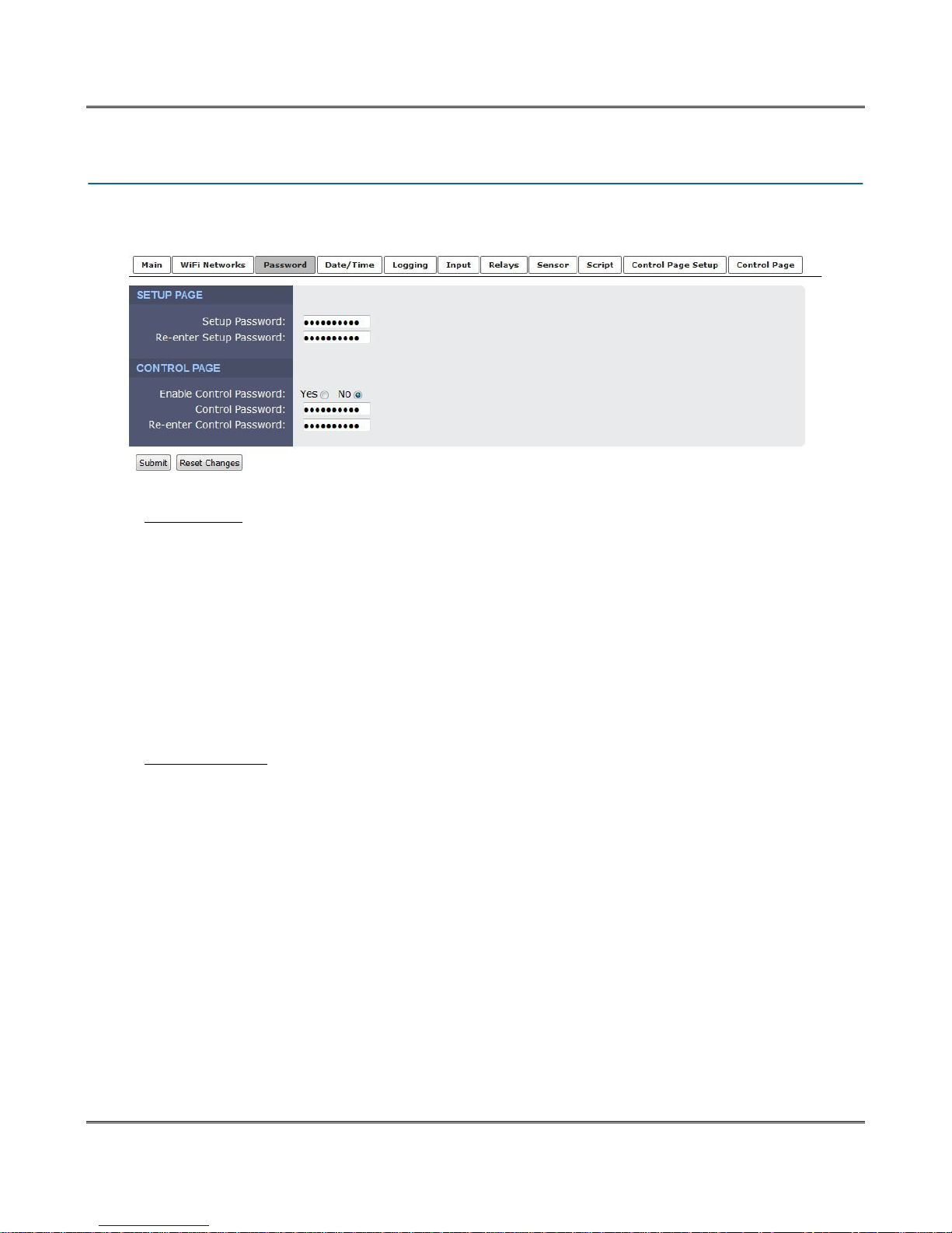
4.3 Password Tab
The XW-210 has separate passwords for the Setup and Control pages. The passwords can be changed
on this page. The username (admin) is fixed and cannot be changed.
SETUP PAGE
Setup Password:
The Setup Password, which is required to access the setup pages, can be modified by entering a new
password here. Passwords that are 8 characters or longer (up to 13 characters can be entered in this
field) with both alphabetic and numeric characters are recommended. For security purposes, the
password will not be displayed as it is entered. Note: the username required for accessing the setup
pages is admin (all lower case). The default Setup Password is webrelay (all lower case).
Re-enter Setup Password:
When the Setup Password is changed, it must be entered twice. One time in the previous field and a
second time in this field. If the password is not entered identically in both fields, the password will not be
changed.
CONTROL PAGE
Enable Control Password:
The user (control) web page is normally viewed without entering a password. For security purposes, a
password can be enabled. When this field is set to Yes, a password will be required to view the control
page. The default setting for this field is No.
Note: Since Modbus has no provision for passing passwords, the Control Page password will disable
Modbus if it is enabled.
Control Password:
The password for the control page can be modified by entering a new password here. Passwords that
are 8 characters or longer (up to 13 characters can be entered in this field) with both alphabetic and
numeric characters are recommended. For security purposes, the password will not be displayed as it is
entered.
Re-enter Control Password:
When the Control Password is changed, it must be entered twice for verification. If the password is not
entered identically in both fields, the password will not be changed.
Page 32 Xytronix Research & Design, Inc.
Page 33
XW-210 WiFi™ Users Manual
4.4 Date/Time Tab
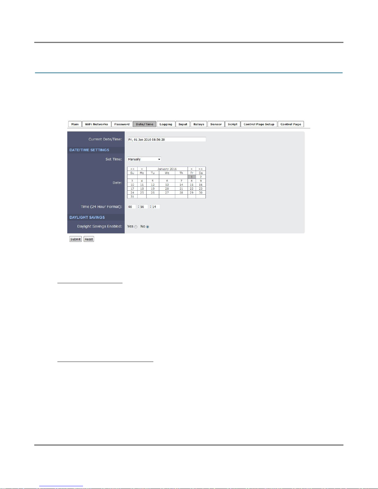
XW-210 uses the time of day for logging (a time stamp is included with each logged event.) The time is
stored and displayed in 24-hour time format. The XW-210 does not have an event scheduler. The time in
the XW-210 is not battery backed and will be lost if the device loses power. For this reason, it is
recommended to use NTP as it will retrieve the time from the NTP server at power-up.
Current Date/Time:
This is the current date and time stored in XW-210. The time is stored and displayed in 24-hour format.
DATE/TIME SETTINGS
Set Time:
This drop-down list offers two options for setting the time: Manually or Sync with NTP server.
The options that follow this field will change based upon how this option is set.
Manually: Requires the user to enter the time and date.
Sync with NTP server: Allows the user to set the clock automatically by using an NTP (Network
Time Protocol) server.
MANUAL TIME CONFIGURATION
Date:
The current date is entered by first selecting the correct month and year, using the left and right arrows at
the top of the calender. The single arrows(< and >) change the month and the double arrows (<< and >>)
change the year. Once the current month and year are displayed, select the correct day, which will then
be highlighted.
Time (24-Hour Format):
Enter the time as HH:MM:SS. (HH represents hours in 24-hour format [00-23], MM represents minutes
[00-59], SS represents seconds [00-59].)
Xytronix Research & Design, Inc. Page 33
Page 34
Web Server XW-210 WiFi™ Users Manual
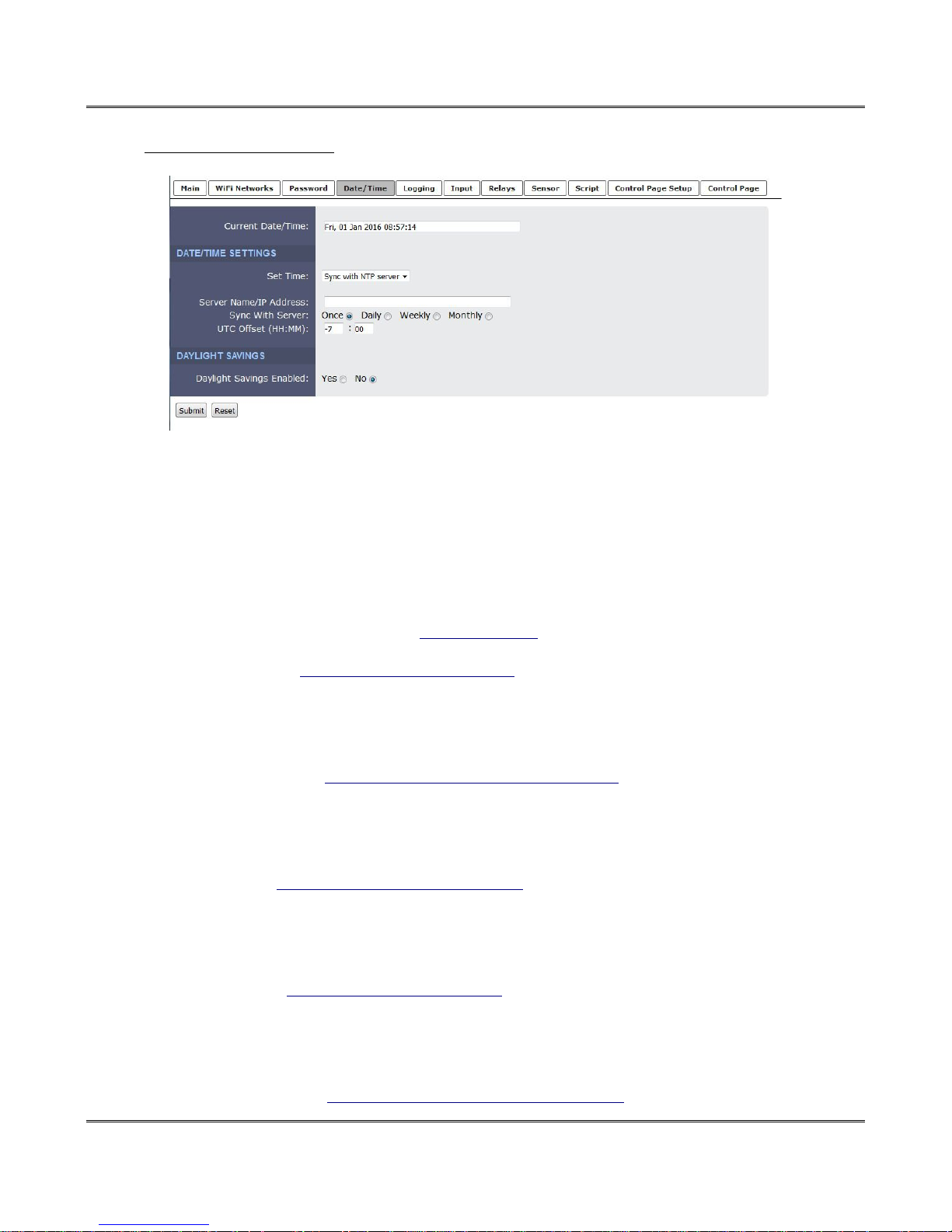
SYNC WITH NPT SERVER
Server Name/IP Address
This field is used to specify the name or IP address of the NTP server. If a name is specified, a
working DNS server address must be entered into the Network settings. If the IP address is
specified, it should be entered in the following format aaa.bbb.ccc.ddd where each of the letters
represents a number between 0 and 255. This field can be up to 40 characters. There is no default
value for this field.
Many NTP Internet servers are available. In addition, many desktop computers will function as an
NTP server (both Mac and PC). If a desktop computer is used, firewall settings may need to be
adjusted to allow for NTP communications on UDP port 123.
Public NTP servers can be found at www.pool.ntp.org. Some of these are listed below.
US Servers (http://www.pool.ntp.org/zone/us):
0.us.pool.ntp.org
1.us.pool.ntp.org
2.us.pool.ntp.org
3.us.pool.ntp.org
North America (http://www.pool.ntp.org/zone/north-america):
0.north-america.pool.ntp.org
1.north-america.pool.ntp.org
2.north-america.pool.ntp.org
3.north-america.pool.ntp.org
Europe (http://www.pool.ntp.org/zone/europe):
0.europe.pool.ntp.org
1.europe.pool.ntp.org
2.europe.pool.ntp.org
3.europe.pool.ntp.org
Australia (http://www.pool.ntp.org/zone/au):
0.au.pool.ntp.org
1.au.pool.ntp.org
2.au.pool.ntp.org
3.au.pool.ntp.org
South America (http://www.pool.ntp.org/zone/south-america):
Page 34 Xytronix Research & Design, Inc.
Page 35

XW-210 WiFi™ Users Manual
0.south-america.pool.ntp.org
1.south-america.pool.ntp.org
2.south-america.pool.ntp.org
3.south-america.pool.ntp.org
Africa (http://www.pool.ntp.org/zone/africa):
1.africa.pool.ntp.org
1.pool.ntp.org
3.pool.ntp.org
Sync With Server
This option allows the user to specify how often the time on XW-210 will be synchronized with the time
server. When the submit button on this page is pressed, XW-210 will immediately synchronize with the
time server. If Daily, Weekly, or Monthly options are selected, XW-210 will thereafter re-synchronize with
the time server at the period interval specified starting at the time of day the settings were submitted. The
default value of this setting is Once (the unit will immediately sync with the NTP server, but will not
automatically sync again until power cycled).
UTC Offset
Time servers return the current time in Universal Time (GMT). It is common for many servers and data
loggers to use GMT as their official time, even when they are not located within the GMT time zone. The
default value for this field is -7 (Mountain Standard Time). For convenience, the time can be converted to
local standard time by entering the offset here. This manual cannot include the UTC Offset for all parts of
the world, but the offset for GMT time and the four major US Time zones are listed here.
GMT Time: 00:00
Eastern Standard Time: -5:00
Central Standard Time: -6:00
Mountain Standard Time: -7:00
Pacific Standard Time: -8:00
Xytronix Research & Design, Inc. Page 35
Page 36

Web Server XW-210 WiFi™ Users Manual
DAYLIGHT SAVINGS
Daylight Savings Enabled:
In many parts of the United States and in some other countries, the time is shifted forward by one hour
during the summer months. This is an effort to conserve energy by making the daylight last longer into
the evening hours. If this option is set to Yes, the time on XW-210 will automatically be shifted forward by
one hour between the hours of 12:00 AM – 5:00 AM on the Daylight Savings Start date set below, and it
will shift back to standard time between the hours of 12:00 AM – 5:00 AM on the Daylight Savings End
date set below. The time change is made at a random time within the previously mentioned, five-hour
time frame, in order to prevent several different devices from simultaneously requesting a time and
overwhelming the NTP server. The default setting is Yes.
Note: Logged data includes a time stamp based upon the current time in the device, so it is possible to
duplicate log times in the spring and miss log times in the fall. To avoid confusion, many servers and data
loggers are set to remain on GMT time and do not shift for daylight savings.
Daylight Savings Start:
This is the date that daylight savings will start. Note that on this date, between the hours of 12:00 AM –
5:00 AM, the current time will be shifted forward by one hour (i.e. the time will jump from 12:02 AM
[00:02] to 1:02 AM [01:02]). By default this is set to the 2nd Sunday in March which is the date used in
the United States.
Daylight Savings End:
This is the date that daylight savings will end. On this date, between the hours of 12:00 AM – 5:00 AM,
the current time will be shifted backward by one hour (i.e. time will jump from 12:02 AM [00:02] to 11:02
PM [23:02] the day before). By default this is set to the 1st Sunday in November which is the date used in
the U.S.
Page 36 Xytronix Research & Design, Inc.
Page 37
XW-210 WiFi™ Users Manual
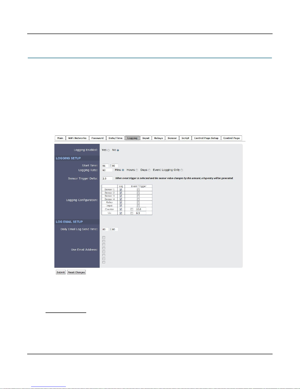
4.5 Logging Tab
XW-210 can be configured to record data such as sensor data and changes in I/O state. Both periodic
and event-based logging are supported. The logged data is stored in internal nonvolatile memory and
can be retrieved by entering the command http://{XW-210 IP address}/log.txt. For more information on
logging, see Section 6.5: Log File.
The log is stored in non-volatile flash memory using a circular buffer (old data is over written). 512Kbytes of memory space is reserved for logging. Log entries are composed of the following components,
5-byte header, 4-byte time stamp and 4 bytes for each sensor selected, 1-byte for input, 4-bytes for the
counter, 1-byte for relay and 4-bytes for Vin. A log of Vin 1 (4 bytes) and the digital input (1 byte) will
occupy 14 bytes per entry.
Note: Changing the log settings will erase the current log file.
Logging Enabled:
When this option is set to Yes, XW-210 will record data as configured on this page. The default setting
for this option is No.
LOGGING SETUP
Start Time:
If a logging interval is specified (periodic logging rather than event logging), logging will occur relative to
this start time. For example, if the start time is 01:00 and the logging rate is 6 hours, logging will occur at
01:00, 07:00, 13:00, and 19:00. Start time is specified in 24-hour time format. The default setting for this
field is 01:00.
Xytronix Research & Design, Inc. Page 37
Page 38

Web Server XW-210 WiFi™ Users Manual
Logging Rate:
This field is used to specify the time period of logging. A numerical value is entered into the text field, and
the unit of time is selected using the adjacent radio buttons. The range of values in this field is 1-20864.
Time units are Minutes, Hours, and Days. Periodic logging can be disabled by selecting the Event
Logging Only radio button.
Sensor Trigger Delta:
XW-210 can be configured to log data when the count, voltage, temperature, or humidity measured by a
sensor changes by the amount specified in this field. This can be set from 1.0 to 9999 units, in 0.1
increments. The default setting for these fields is shown below.
Sensor Trigger Delta
Vin 2.0 V
Temperature 2.0º
Humidity 2.0%
Counter 2 counts
Logging Configuration:
Check the items you wish to log. Check the event trigger box if the corresponding I/O should be allowed
to cause the I/O state to be logged. For example, if the check box for the relay in the Event Trigger
column is checked, a log entry will be entered each time the relay changes state even if the log is
configured to only log periodically. Log entries recorded due to an event will not interfere with periodic
logging.
LOGGING EMAIL SETUP
Daily Email Log Send Time:
The XW-210 can periodically Email the log file at a specific time. For example; use this feature to Email
the temperature log of a restaurant food cooler once per day to provide the documentation required for
health regulations.
Use Email Address:
These check boxes determine what Email addresses the periodic data log is sent to. Up to eight
email addresses can be assigned. The same data log is sent to each Email address. For Email
notification to work, the XW-210 must have a properly configured network connection and a SMTP
server must be defined. When an Email address is entered via the WiFi Networks tab, the check boxes
will show the respective Email addresses.
Page 38 Xytronix Research & Design, Inc.
Page 39
XW-210 WiFi™ Users Manual
4.6 Input Tab
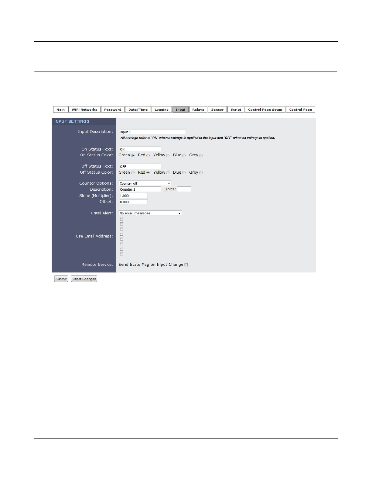
These settings determine how the XW-210 processes the digital input. The digital input has a counter
which counts the number of input pulses. The input has a set debounce of 20ms before counters or
events are processed. This page provides configuration options for the input and its counter.
Input Description:
This text is used to describe the function of the digital input. The text appears to the left of corresponding
input status on the Control Page, and in email messages when email alerts are enabled. This field may
be up to 24 characters long. Enter a descriptive name such as “Stockroom Door”.
On Status Text:
The text in this field specifies the text that will be displayed in the Control Page and in email messages
when the input is ON (switch is closed). Up to 15 characters may be entered in this field. Enter a
descriptive status such as “Door is Open”.
On Status Color:
This field specifies the color that will be displayed on the Control Page when the input is considered On.
Options are Green, Red, Yellow, Blue and Grey.
Off Status Text:
The text in this field specifies the text that will be displayed in the Control Page and in email messages
when the input is Off (switch is open). Enter a descriptive status such as “Door is Closed”.
Xytronix Research & Design, Inc. Page 39
Page 40

Web Server XW-210 WiFi™ Users Manual
Off Status Color:
This field specifies the color that will be displayed on the Control Page when the input is considered Off.
Options are Green, Red, Yellow, Blue and Grey.
Counter Options
This settings determines what triggers the counter to increment. The default setting for this field is:
“Counter off”.
Counter off: No input transitions will be counted.
Increment when input on: The counter will increment each time the input turns on.
Increment when input off: The counter will increment each time the input turns off.
Increment when input changes: The counter will increment each time the input changes on or
off.
Description
This text field is used to describe the counter. The text appears to the left of the corresponding counter
on the Control Page, and in email messages when email alerts are enabled. This field may be up to 9
characters long. The default text is “Count 1”.
Units
This text field is used to describe the units counted. The text appears to the right of the counter reading.
This field may be up to 4 charters long.
Slope (Multiplier)
The counter value can be scaled into engineering units. The XW-210 reads the raw value from the
counter and calculates a new value in engineering units. This scaled value is calculated using a linear
Y=mX+b formula.
Scaled Value = Slope * Count + Offset
The calculated scaled value is used for trigger logs, email messages, control page, XML page, and
returned when Modbus values are read.
The “slope” in the formula above is provided by the user and is entered in this field. When both the slope
and offset are set to their default values (m=1 and y=0) the scaled value equals the actual count.
Offset
The “offset” in the formula above is provided by the user and is entered in this field. The default value for
this field is 0.
Email Alert:
Simple email messages can be sent in response to changes in the digital input. This setting is used to
specify what conditions, if any, will cause email messages to be sent.
No email Messages: No email messages will be sent due to input conditions.
Send email when Input On: Email notifications will be sent when the input is on.
Send email when Input Off: Email notifications will be sent when the input is off.
Send email when Input Changes State: Email notifications will be sent when the input turns
on or off.
Use Email Address:
These check boxes determine what Email addresses the input alert message is sent to. Up to eight
Email addresses can be assigned. The same message is sent to each Email address. For email
notification to work, the XW-210 must have a properly configured network connection and a SMTP
Page 40 Xytronix Research & Design, Inc.
Page 41

XW-210 WiFi™ Users Manual
server must be defined. When an Email address is entered via the WiFi Networks tab, the check boxes
will show the respective Email addresses.
Remote Service:
When this box “Send State Message on Input Change” is checked, State messages will be sent
whenever the input state changes. Remote Services must be enabled and properly configured for this
feature to be effective.
Xytronix Research & Design, Inc. Page 41
Page 42
Web Server XW-210 WiFi™ Users Manual
4.7 Relay Tab
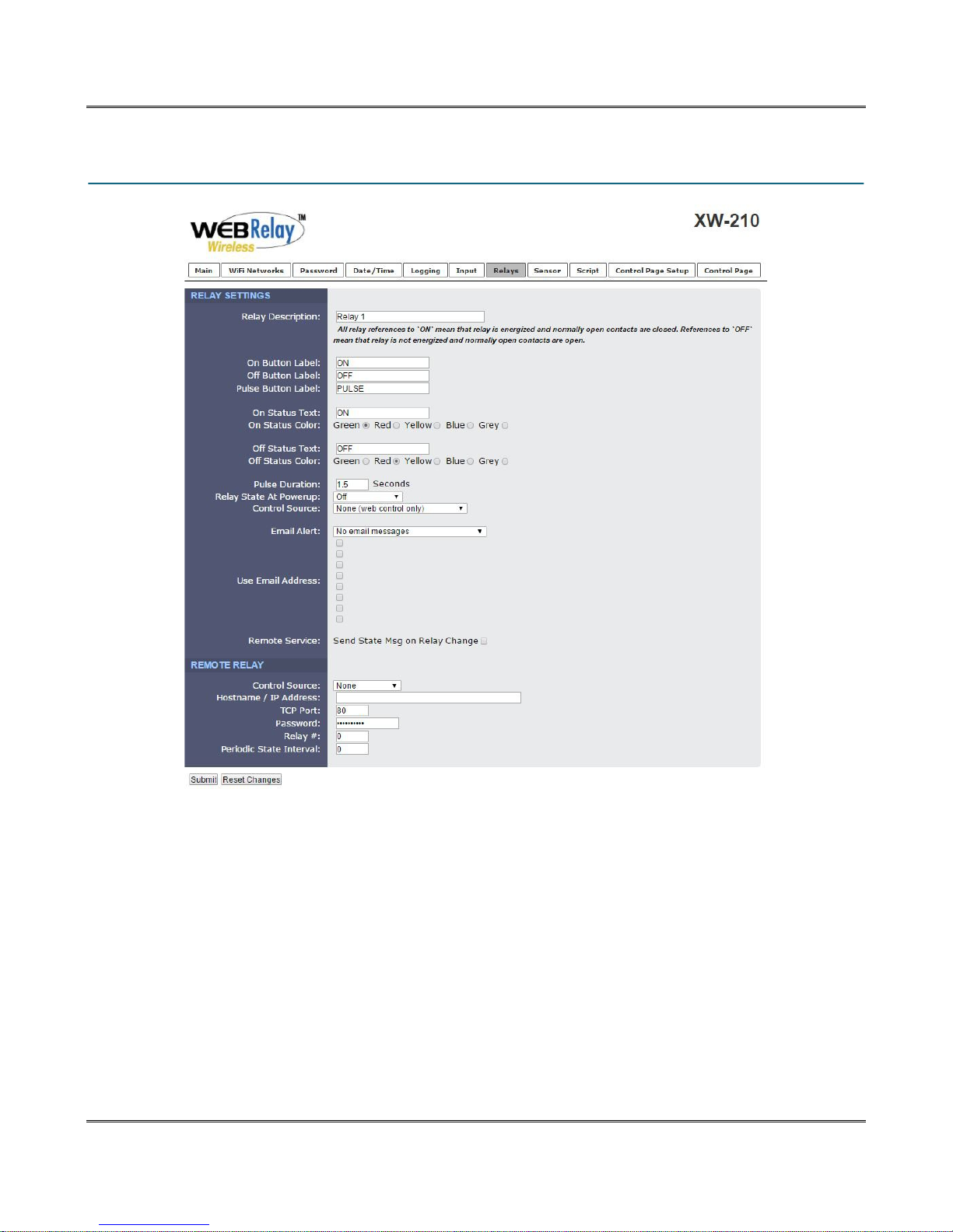
Description
This text field is used to describe the function of the relay. The text appears to the left of the
corresponding relay status on the Control Page and in the email message when email alerts are enabled.
Up to 24 characters may be entered in this field. The default text is “Relay 1”.
On Button Label
The text entered in this field appears in the 'On' button for the corresponding output on the Control Page.
Up to 15 characters may be entered in this field. The default text is “On”.
Off Button Label
The text entered in this field appears in the 'Off' button for the corresponding output on the Control Page.
Up to 15 characters may be entered in this field. The default text is “Off”.
Pulse Button Label
The text entered in this field appears in the 'Pulse' button for the corresponding output on the Control
Page 42 Xytronix Research & Design, Inc.
Page 43

XW-210 WiFi™ Users Manual
Page. Up to 15 characters may be entered in this field. The default text is “PULSE”.
On Status Text
The text in this field specifies the text that will be displayed in the Control Page and in email messages
when the relay is On. Up to 15 characters may be entered in this field. The default text is “On”.
On Status Color
This field specifies the color that will be displayed on the Control Page when the relay is considered On.
Options are Green, Red, Yellow, Blue and Grey. The default color is Green.
Off Status Text
The text in this field specifies the text that will be displayed in the Control Page and in email messages
when the relay is Off. Up to 15 characters may be entered in this field. The default text is “Off”.
Off Status Color
This field specifies the color that will be displayed on the Control Page when the relay is considered Off.
Options are Green, Red, Yellow, Blue and Grey. The default color is Red.
Pulse Duration
When XW-210 receives a pulse command for the relay (through the web page or through a command),
the relay will pulse for the time specified in this field. Note that when a pulse command is sent through
the command interface (XML or ModBus), the command can include a pulse time which will over-ride
this value (for that pulse only). The time is specified in seconds and can range from 0.1 seconds to
86400 seconds in 0.1 second increments. The default time is 1.5 seconds.
Relay State at Power up
This drop down menu lets the user specify the state of the relay when the XW-210 is powered up. The
following options can be selected:
Off: The relay will be off upon power up (this is the default setting.)
On: The relay will be on upon power up.
Evaluate Logic: Upon power up, the control source and action are evaluated to determine the
proper state of the relay.
Control Source
These drop down menus specify what input or sensor controls the state of the relay. The following
options can be selected:
None: The state of the relay will be controlled only by the web page.
Digital Input: The state of the relay will be controlled by the digital input and/or the web page.
1-Wire Sensor: The state of the relay will be controlled by a 1-Wire Sensor and/or the web
page.
Depending on the Control Source selected, the menu will change.
If Digital Input is selected the following Action options are available:
Set relay equal input: When the input is on, the relay is on. When the input is off, the
relay is off.
Set relay opposite of input: When the input is on, the relay is off. When the input is off,
Xytronix Research & Design, Inc. Page 43
Page 44

Web Server XW-210 WiFi™ Users Manual
the relay is on.
Latch relay on when input [on, off, changes] (reset via web): The relay latches on when
the input is [on, off, changes]
Latch relay off when input [on, off, changes] (reset via web): The relay latches off when
the input is [on, off, changes]
Toggle relay when input [on, off, changes]: The relay changes state when the input
is [on, off, changes]
Pulse relay when input [on, off, changes]: The relay is pulsed when the input
is [on, off, changes]
If 1-Wire Sensor is selected, choose the sensor number. For each sensor the following Action options are
available:
Set Relay On: The relay turns on when [Alarm 1, Alarm 2, Alarm 1 or Alarm 2] is true
Set Relay Off: The relay turns off when [Alarm 1, Alarm 2, Alarm 1 or Alarm 2] is true
Latch Relay On: The relay latches on when [Alarm 1, Alarm 2, Alarm 1 or Alarm 2] is true
Latch Relay Off: The relay latches off when [Alarm 1, Alarm 2, Alarm 1 or Alarm 2] is true
Toggle Relay: The relay changes state when [Alarm 1, Alarm 2, Alarm 1 or Alarm 2] is true
Pulse Relay: The relay is pulsed when [Alarm 1, Alarm 2, Alarm 1 or Alarm 2] is true
Email Alert:
Simple email messages can be sent in response to relay state changes. This parameter is used to
specify what relay state changes, if any, will cause email messages to be sent. Note that email
notification will work only if the email settings are correctly set up in the Network setup page. The
following options are available:
No Email Messages: No email notifications will be sent due to relay state changes.
Send Email when relay on: Email notifications will be sent when relay state changes to on.
Send Email when relay off: Email notifications will be sent when relay state changes to off.
Send Email when relay changes state: Email notifications will be sent when relay changes state
from off to on or on to off.
Use Email Address:
These check boxes determine what Email addresses the relay alert message is sent to. Up to eight
Email addresses can be assigned. The same message is sent to each Email address. For email
notification to work, the XW-210 must have a properly configured network connection and a SMTP
server must be defined. When an Email address is entered via the WiFi Networks tab, the check boxes
will show the respective Email addresses.
Remote Service:
When this box “Send State Message on Relay Change” is checked, State messages will be sent
Page 44 Xytronix Research & Design, Inc.
Page 45

XW-210 WiFi™ Users Manual
whenever the selected source changes. Remote Services must be enabled and properly configured for
this feature to be effective.
The digital input can be configured to control the relay contacts of another ControlByWeb™ device (such
as WebRelay™) at a remote location. The ‘Remote Service Options’ setting is used to specify if and how
the input affects the remote relay. The options in the drop-down list are described below. Note that in all
cases, input changes will only affect the remote relay at the time the input is changed. Once the change
has taken place, the state of the input has no effect on the state of the remote relay. In other words, if the
input causes the remote relay to go on, a user may turn that remote relay off from the web browser, even
if the local input is still on.
REMOTE RELAY
The XW-210 can be configured to control a relay on other ControlByWeb devices across the network.
These relays are called remote relays.
Control Source:
Select the resource to control the remote relay. The following options are available:
None: No commands are sent to a remote relay
Digital Input: The state of the remote relay will be controlled by the digital input.
Relay: The state of the remote relay will be controlled by the local relay.
1-Wire Sensor: The state of the remote relay will be controlled by 1-Wire Sensor alarms.
Action:
These drop down menus specify what action to take when a criteria is met. The actions change
depending on what control source has been selected. The following section lists the options available
based for each control source selected.
If Digital Input is selected the following Action options are available:
Remote command equals input: When the input is on, a command is sent to the remote device to
set the relay state to on. When the input is off, a command is sent to the remote device to set the
relay state to off.
Remote command opposite of input: When the input is on, a command is sent to the remote
device to set the relay state to off. When the input is off, a command is sent to the remote device to
set the relay state to on.
Send on command when input [on, off, changes] (no off command): When the input is [on, off,
changes] a command is sent to the remote device to set the relay state to on. No off commands are
sent to the remote device.
Send off command when input [on, off, changes] (no on command): When the input is [on, off,
changes] a command is sent to the remote device to set the relay state to off. No on commands are
sent to the remote device.
Send toggle command when input [on, off, changes]: When the input is [on, off, changes] a
command is sent to the remote device to toggle the relay (change the remote relay to the state
opposite of its current state).
Send pulse command when input [on, off, changes]: When the input is [on, off, changes] a
Xytronix Research & Design, Inc. Page 45
Page 46

Web Server XW-210 WiFi™ Users Manual
command is sent to the remote device to pulse the relay.
If Relay is selected the following Action options are available:
Remote command equals relay: When the local relay is on, a command is sent to the remote
device to set the relay state to on. When the local relay is off, a command is sent to the remote
device to set the relay state to off.
Remote command opposite of relay: When the local relay is on, a command is sent to the remote
device to set the relay state to off. When the local relay is off, a command is sent to the remote
device to set the relay state to on.
Send on command when relay [on, off, changes] (no off command): When the local relay is [on,
off, changes], a command is sent to the remote device to set the relay state to on. No off commands
are sent to the remote device..
Send off command when relay [on, off, changes] (no on command): When the local relay is [on,
off, changes] a command is sent to the remote device to set the relay state to off. No on commands
are sent to the remote device.
Send toggle command when relay [on, off, changes]: When the local relay is [on, off, changes] a
command is sent to the remote device to toggle the relay (change the remote relay to the state
opposite of its current state).
Send pulse command when relay [on, off, changes]: When the local relay is [on, off, changes] a
command is sent to the remote device to pulse the relay.
If 1-Wire Sensor is selected, choose the sensor number. For each sensor the following action options are
available:
Send On Command When [Alarm1, Alarm2, Alarm1 or Alarm2]: A command is sent to the remote
device to set the relay state to on when [Alarm1, Alarm2, Alarm1 or Alarm2] becomes true. A
command is sent to the remote device to set the relay state to off when [Alarm1, Alarm2, Alarm1 or
Alarm2] becomes false.
Send Off Command When [Alarm1, Alarm2, Alarm1 or Alarm2]: A command is sent to the remote
device to set the relay state to off when [Alarm1, Alarm2, Alarm1 or Alarm2] becomes true. A
command is sent to the remote device to set the relay state to on when [Alarm1, Alarm2, Alarm1 or
Alarm2] becomes false.
Send On Command When [Alarm1, Alarm2, Alarm 1 or Alarm2] (no off command): A command
is sent to the remote device to set the relay state to on when [Alarm1, Alarm2, Alarm1 or Alarm2]
becomes true. No off command is sent.
Send Off Command When [Alarm1, Alarm2, Alarm 1 or Alarm2] (no on command): A command
is sent to the remote device to set the relay state to off when [Alarm1, Alarm2, Alarm1 or Alarm2]
becomes true. No on command is sent.
Send toggle command when [Alarm 1, Alarm2, Alarm 1 or Alarm2]: A command is sent to the
remote device to toggle the relay (change the remote relay to the state opposite of its current state
when [Alarm1, Alarm 2, Alarm 1 or Alarm 2] becomes true.
Send Pulse Command When [Alarm1, Alarm2, Alarm1 or Alarm2]: A command is sent to the
remote device to pulse the relay when [Alarm1, Alarm 2, Alarm 1 or Alarm 2] becomes true.
Page 46 Xytronix Research & Design, Inc.
Page 47
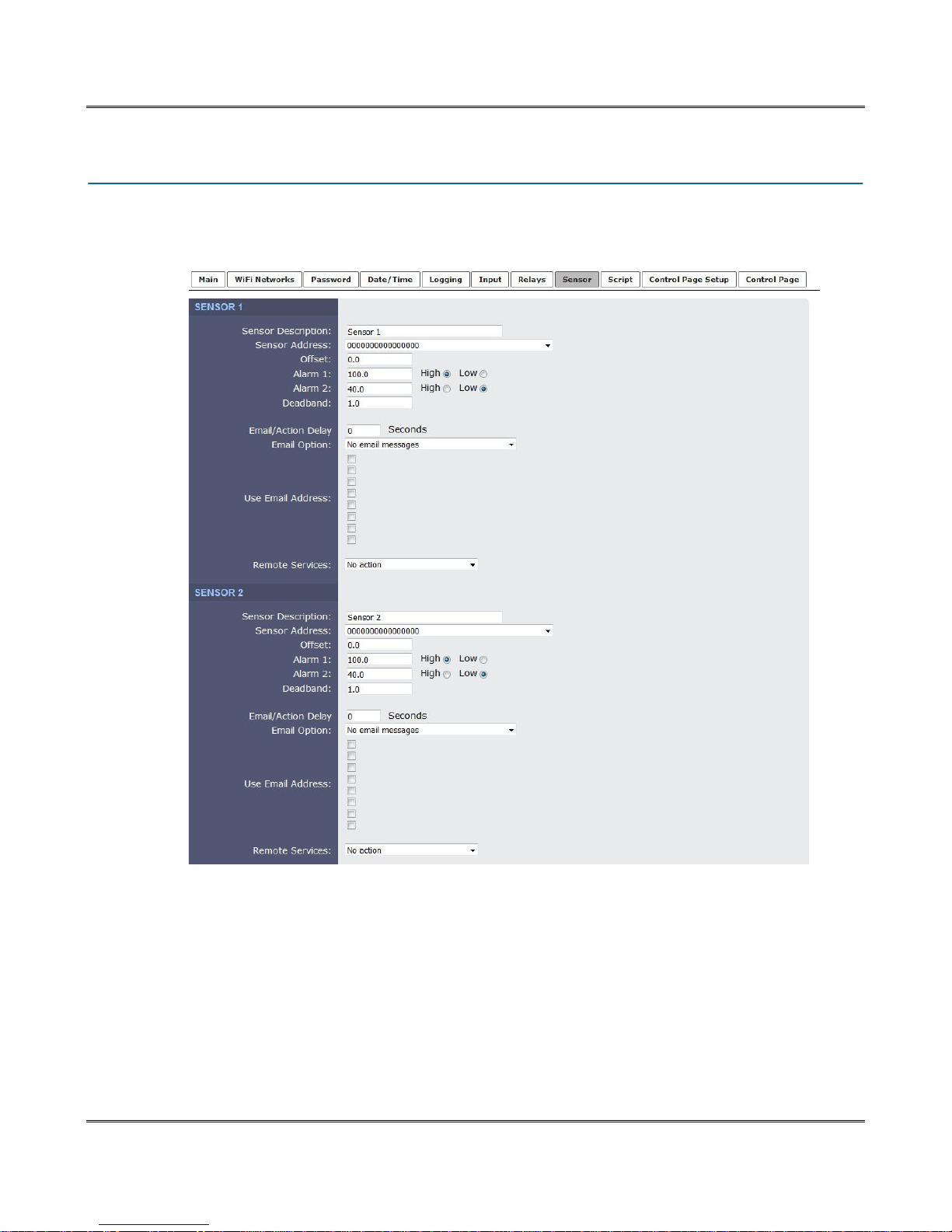
XW-210 WiFi™ Users Manual
4.8 Sensor Tab
Up to four temperature or other Xytronix 1-wire sensors can be connected to XW-210. Each of the1-wire
sensors have specific settings. The settings for the first 2 sensors are shown below.
Sensor Description:
This text will appear in email messages when email alerts are enabled as well as to the left of the
corresponding temperature/humidity value on the Control Page. This field may be up to 35 characters
long.
Sensor Address:
Each sensor connected to XW-210 must be associated (assigned) to a sensor number. Every sensor
comes from the factory with a unique, non-changeable address. When the sensors tab is selected, the
XW-210 scans the bus for sensors. The addresses of the sensors that are found on the bus are listed in
the drop-down list. For each sensor number (Sensor 1... Sensor 4), select the address of the appropriate
Xytronix Research & Design, Inc. Page 47
Page 48
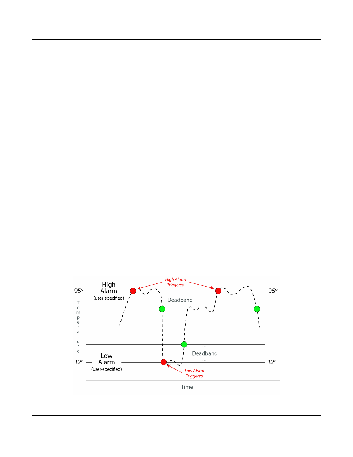
Web Server XW-210 WiFi™ Users Manual
sensor from the drop-down list.
Selecting sensors is simplest when the sensors are connected to the bus one at a time. The procedure is
to start with one sensor and associate it with the appropriate sensor number by selecting the sensor
address within the appropriate drop-down list. Submit the page, connect a second sensor, and press the
Sensors tab. Associate the second sensor to the appropriate sensor number. Continue this procedure
until all sensors are set up.
Offset:
The value of the offset will be added to the sensor's reading. Normally this should be set to zero.
Alarm 1:
This setting is used to set the trigger point for an alarm condition. The numeric field specifies the
temperature/humidity at which the alarm is triggered. The “High” and “Low” radio buttons indicate
whether the alarm is triggered as a high or low alarm. A high alarm is triggered when the sensor reading
exceeds the alarm value, and a low alarm is occurs when the sensor reading falls below the alarm value.
Generally this value will be static, but a Register can be used as a trigger point for an alarm condition as
well. To use a Register select the desired Register using the drop down box. The value of a Register can
be changed through a basic script, and directly through the control page.
Alarm 2:
This is a second alarm trigger that works similarly to Alarm 1
Deadband:
The deadband (hysteresis) prevents alarms from triggering excessively when the measurement value
vacillates around the trigger point. With high alarms, the measurement must fall below the high alarm
point minus the dead band before the high alarm will be triggered again. Likewise the deadband on the
low alarm requires the measurement to rise above the low alarm point plus the deadband before the low
alarm will be triggered again.
For example, if the dead band is set to 0.5°C, and a high alarm is set at 13°C, the high alarm will occur at
13°C; however, it will not turn off until the temperature drops below 12.5°C (13°C - 0.5°C).
Page 48 Xytronix Research & Design, Inc.
Page 49

XW-210 WiFi™ Users Manual
Email/Action Delay:
Number of seconds to delay before considering the sensor to be in an alarm state. For example, if the
temperature sensor is monitoring a freezer and is mounted near the door, the sensor may go in to an
alarm state each time the door is opened and cause false alarms. The delay will cause the temperature
to be in an alarm state for the specified number of seconds before processing any triggers based on that
sensors alarm state.
Email Option:
Simple email messages can be sent in response to alarm conditions. This parameter is used to specify
what alarm conditions, if any, will cause email messages to be sent. Email notifications will work only if
email is correctly setup in the WiFi Networks tab.
No email Messages: No email messages will be sent due to alarm conditions.
Send email on Alarm 1: Email notifications will be sent due to an Alarm 1 condition.
Send email on Alarm 2: Email notifications will be sent due to an Alarm 2 condition.
Send email on Alarm 1 and Alarm 2: Email notifications will be sent due to an Alarm 1 or Alarm
2 condition.
Send email on Alarm 1, Alarm 2 and normal: Email notifications will be sent when Alarm 1 or
Alarm 2 occur, or when normal conditions are restored.
Use Email Address:
These check boxes determine what Email addresses the temperature alarm message is sent to. Up to
eight Email addresses can be assigned. The same message is sent to each Email address. For email
notification to work, the XW-210 must have a properly configured network connection and a SMTP
server must be defined. When an Email address is entered via the WiFi Networks tab, the check boxes
will show the respective Email addresses.
Remote Services:
The XW-210 can be configured to send messages to other ControlByWeb™ products that are located at
a remote location on the network. This field specifies the action taken due to a temperature alarm
condition. The following actions are available:
No Action: No action is taken.
Send state on Alarm 1: state.xml will be sent when Alarm 1 becomes true.
Send state on Alarm 2: state.xml will be sent when Alarm 2 becomes true.
Send state on Alarm 1 and Alarm 2: state.xml will be sent when Alarm 1 or Alarm 2 becomes
true.
Xytronix Research & Design, Inc. Page 49
Page 50
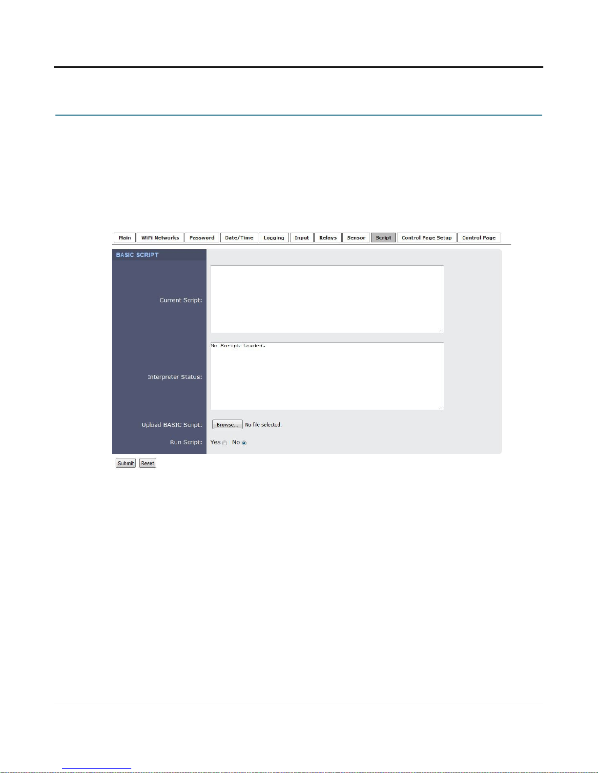
Web Server XW-210 WiFi™ Users Manual
4.9 Script Tab
The XW-210 can run custom programs written in a simplified version of BASIC. This page is used to load
and execute these programs. Before it can be loaded to the XW-210, a script must first be prepared as a
.txt file. The file must then be uploaded to XW-210 via the Script tab. The maximum size of script that
can be uploaded to the device is 4-Kbytes. Information on writing a basic program for XW-210 can be
found in Section 6.7: Basic Scripts.
An ASCII standard text file format should be used, such as Windows Notepad, Programmer's Notepad,
vi, or other text editor that output the file as a .txt. Rich Text Format (.rtf) used by Microsoft WordPad is
NOT compatible.
Current Script
This field displays the .txt file that is uploaded to XW-210. Text displayed in this screen cannot be edited.
In order to edit any script, it must be rewritten in the .txt file and uploaded again.
Interpreter Status
This field displays whether the program is running, has stopped or finished, or if there are errors
contained in the script. If there are errors in the script, the line on which the error occurred is displayed.
Upload BASIC Script
This field displays the script selected to be uploaded to the device. To upload a script to XW-210, click
the Browse button, find the .txt file previously created, and select Open. The location of the file should
appear in the neighboring field. To upload the script to the unit, select Submit.
Run Script
This option selects whether or not the selected script will be run after it has been uploaded. The Submit
button must be clicked to run the script.
Page 50 Xytronix Research & Design, Inc.
Page 51

XW-210 WiFi™ Users Manual
4.9.1 Example Script
The following is an example script which monitors a door switch. An alarm sounds after a door has been
open for 10 seconds and turns off if the door is closed. It includes a trigger to exit the timer if the input
turns off before 10 seconds has elapsed. This helps insure that the alarm will only turn on if the door has
been open for 10 seconds.
'This example will turn on a relay after an input has been on for 10 seconds
LET relay1 = 0 'Make sure the relay is off when the script starts
DO 'Begin main program loop
LOOP 'Loop main program
END 'End main program loop
SUB delay 'SUB function
END SUB 'End of the SUB routine
IF input1 = 1 THEN 'Checks if input 1 is on - Door is open
CALL delay 'Calls the delay function
IF input1 = 1 THEN 'After the delay is done, it will check the door again
LET relay1 = 1 'Turns the relay on, sounding the alarm
END IF
ELSE 'If input1 is off - door is closed
LET relay1 = 0 'Turn relay1/alarm off after closed door
END IF 'End of IF input1 = 1
LET t1 = 100 'Set timer = 10.0 seconds
DO WHILE t1 > 0 'Loop while timer is counting down to 0.0 seconds
IF input1 = 0 THEN 'If the input turns off (door closed), exit loop
LET t1 = 0 'Sets timer to 0 to exit loop
END IF 'End of IF input1 = 0
LOOP 'Loop the DO WHILE statement above
Xytronix Research & Design, Inc. Page 51
Page 52
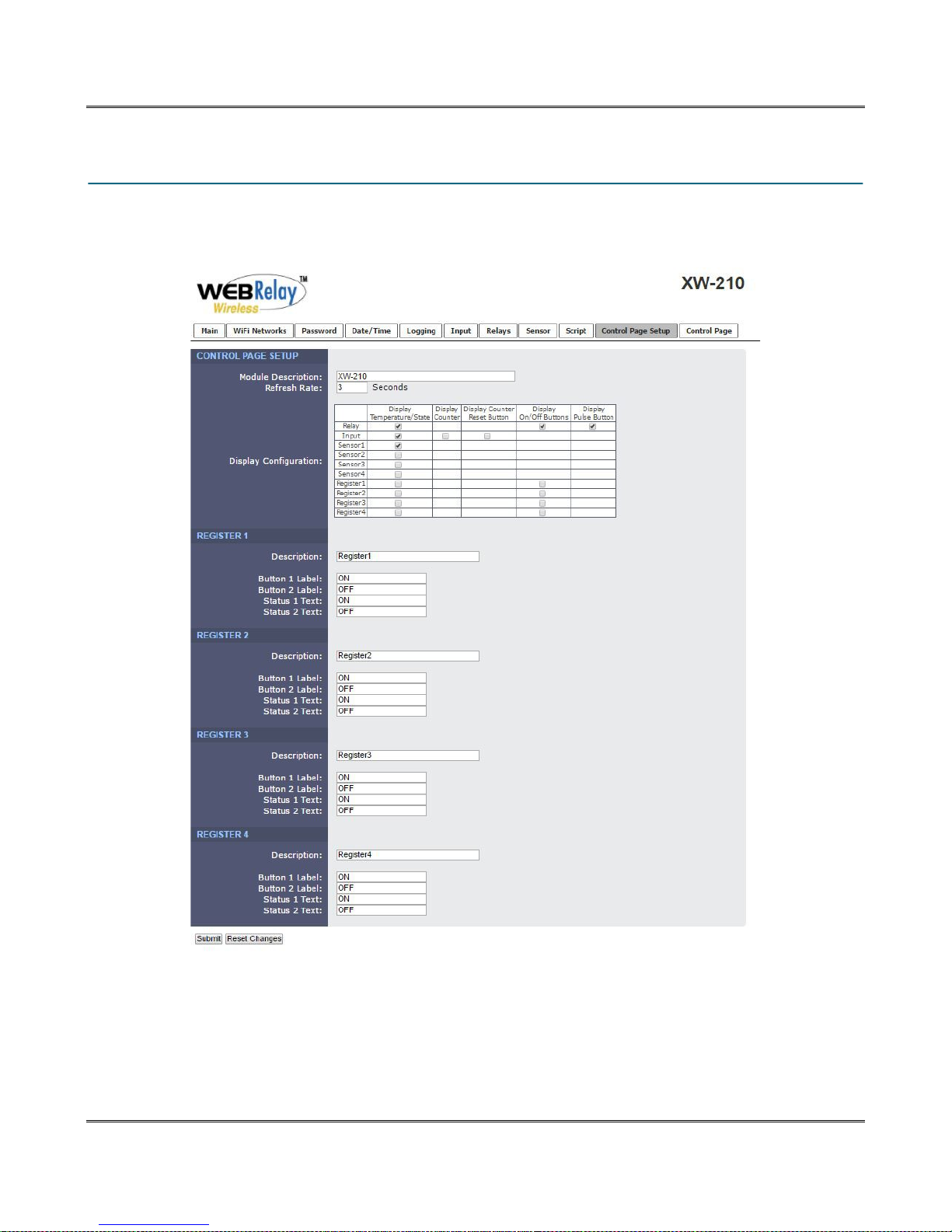
Web Server XW-210 WiFi™ Users Manual
4.10 Control Page and Register Setup Tab
The Control Page Setup page is used to set parameters that affect the view of the Control Page,
including what measurement values and buttons are to be shown.
Module Description
The text entered here appears at the top of the Control Page. It also appears in the header of the email
text when the email notification is used. This field can be up to 40 characters in length. The default text is
“XW-210”.
Page 52 Xytronix Research & Design, Inc.
Page 53

XW-210 WiFi™ Users Manual
Refresh rate:
How often the Control Page status is updated. The default value is 3 seconds.
Display Configuration
These check boxes select which input/output resource is displayed on the control page. Each check box
determines whether or not the status of the resource is displayed.
Relay: Determines if the relay status and/or what buttons are visible on the control page.
Input: Determines if the input status is visible on the control page.
Display Counter: Determines the visibility of the counter value on the control page.
Sensors (1-4): Determines the visibility of the 1-wire sensor readings on the control page.
Registers (1-4): Determines the visibility of the registers on the control page.
Registers:
Registers can be changed externally thru the Control Page, XML requests or the BASIC script. This
allows a BASIC script to react to user input. These variables are considered to be floating point numbers,
just like other variables in the BASIC script. This section has settings for each of the registers.
Description
Text entered here will be displayed in the left column of the control page. Up to 14 characters may be
entered here. The default text is “Register 1”.
Button 1 Label
This text field is used to describe the function of button 1 of the selected Register. When the user clicks
button 1, the Register is set to 1. The text also appears to the right of the corresponding Register status.
Up to 9 characters may be entered here. By default, this text is “ON”.
Button 2 Label
This text field is used to describe the function of button 2 of the selected Register. When the user clicks
button 2, the Register is set to 0. The text also appears to the right of the corresponding Register status.
Up to 9 characters may be entered here. By default, this text is “OFF”.
Status 1 Text
The text in this field specifies the text that will be displayed when the Register is value 1. The text also
appears in the status column on the Control Page.
If the Register is any other value than 1 or 0, the value itself will be displayed in the same column. Up to
9 characters may be entered here. By default the text is “ON”
Status 2 Text
The text in this field specifies the text that will be displayed when the Register is value 0. The text also
appears in the status column on the Control Page.
If the Register is any other value than 1 or 0, the value itself will be displayed in the same column. Up to
9 characters may be entered here. By default the text is “OFF”.
Xytronix Research & Design, Inc. Page 53
Page 54
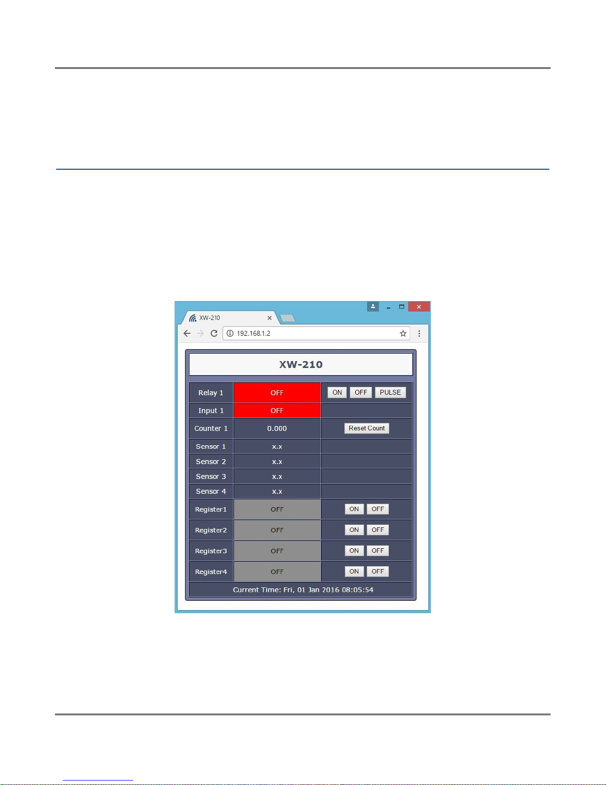
Control Page XW-210 WiFi™ Users Manual
Section 5: Control Page
The relay, digital input and temperature sensors can be monitored and controlled using a web browser,
by sending text commands to an XML status/control page, and/or by sending Modbus/TCP requests.
5.1 Browser Operation
Once the XW-210 is set up, users can access the Control Page using a web browser. There are two
ways to do this. The first is by typing the IP address of the XW-210 directly into the web browser address
bar. For example, using the default IP address, the user would enter http://192.168.1.2. If the IP address
is changed from the default, the user must use the new IP address. Note that if any port is used other
than the default port 80, the port must also be included in the request. For example, accessing the unit at
port 8000 would be as follows: http://192.168.1.2:8000.
The following screen appears when the Control Page is requested from the address bar. This example
has all of the optional resources enabled. The I/O on the control page updates every three seconds.
The Control Page is normally what users see and use and it can be highly configured to fit your needs.
The Control Page Setup tab has check boxes that determine if a specific resource is displayed or not.
The description (text) shown for certain rows is also specified in the Control Page Setup tab.
Page 54 Xytronix Research & Design, Inc.
Page 55

XW-210 WiFi™ Users Manual
Header
Displays the text entered in the Module Description Text field on the Control Page Setup tab in the setup
pages. This is usually a description of the application such as “2nd Floor Freezer”.
Input
This row displays the current state of the digital input. The text in the left column (by default reads “Input
1”) is specified in the description field of the Input tab in the setup pages.
Counter
A cumulative count of OFF to ON states of the digital input. A reset button can be enabled which resets
the counter.
Relay
This row displays the current state of the internal relay and has buttons to allow the user to change the
relay state. The text in the left column (by default reads “Relay 1”) is specified in the description field of
the Relay tab in the setup pages. The state of the relay is shown to the right of the relay description text.
By default, the status text will read ON or OFF; however, the status text can be changed in the Relay tab.
To the right of the relay status, three buttons provide on/off and pulse control of the relay. The buttons
can be removed when not needed (in the Control Page Setup tab) and the text within the buttons can be
customized (in the Relay tab).
Sensor 1-4
These fields display the current temperature or other values measured by the associated sensors. Each
sensor has a description field specified in the Description field in the Sensors tab in the setup pages.
Registers
These rows display the current state of the four registers used in the BASIC script. The state of the
register is shown to the right of the description text. By default the status text will read ON or OFF when
the register is a value of 1 or 0 respectively. To the right of the register status, two buttons are provided to
control the state of the register. These buttons can be enabled or disabled in the Control Page Setup tab.
Xytronix Research & Design, Inc. Page 55
Page 56
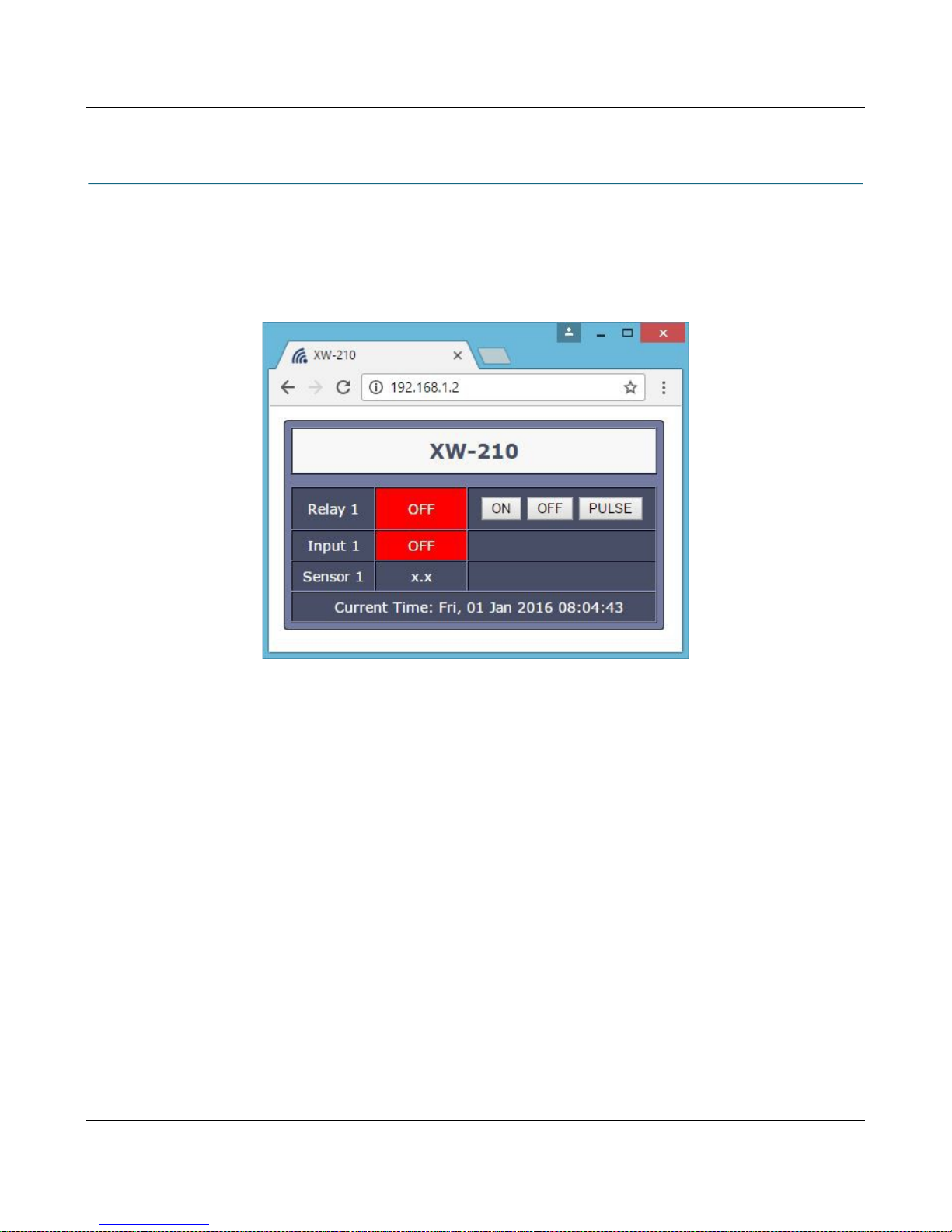
Control Page XW-210 WiFi™ Users Manual
5.2 Control Page Tab
The second method of accessing the control page is through the setup pages
(http://192.168.1.2/setup.html). Clicking the Control Page Tab will open a new browser window and
display the control page shown below. To access the setup tabs again, click on the XW-210 Setup tab in
your browser to return to the previous browser window.
Page 56 Xytronix Research & Design, Inc.
Page 57
XW-210 WiFi™ Users Manual
Section 6: Auxiliary Operations
6.1 XML
Custom XML computer applications may be created to monitor and control the XW-210. This method
does not use a web browser. There is a single XML page that can be used to monitor and control the
XW-210, state.xml. The XW-210 does not support diagnostics.xml.
6.1.1 state.xml
XML Monitor All Functions
The state of the Relays, Inputs, Sensors, Registers, and Vin can be monitored by sending a request to
port 80 (or port specified in setup). This can be demonstrated by entering the following URL into the
address bar of a web browser (substituting the IP address as necessary):
http://192.168.1.2/state.xml
The following state.xml page is returned:
<datavalues>
</datavalues>
<input1state>0</input1state>
<relay1state>0</relay1state>
<units>F</units>
<sensor1>x.x</sensor1>
<sensor2>x.x</sensor2>
<sensor3>x.x</sensor3>
<sensor4>x.x</sensor4>
<s1Alrm>0</s1Alrm>
<s2Alrm>0</s2Alrm>
<s3Alrm>0</s3Alrm>
<s4Alrm>0</s4Alrm>
<count1>23</count1>
<register1>0.00</register1>
<register2>0.00</register2>
<register3>0.00</register3>
<register4>0.00</register4>
<vin>9.577</vin>
<time>1343647469</time>
The numbers enclosed by the tags, <tag>, indicate the current state or value monitored by XW-210.
Values for each tag are described in the table below.
XML computer applications will open a TCP/IP socket with the XW-210 and send a GET command
followed by the state.xml command string. (See Section 6.2: HTTP Get Requests for instructions on
using GET.)
XML Tags* Monitor Values
<input1state>
0=off (voltage not applied to input one)
1=on (voltage applied to input one)
<relay1state>
0=off (coil one off)
1=on (coil one energized)
<units>
F=Fahrenheit
C=Celsius
Xytronix Research & Design, Inc. Page 57
Page 58
Auxiliary Operations XW-210 WiFi™ Users Manual
XML Tags* Monitor Values
<sensorX>
<sXAlarm>
<count1>
<registerX>
<vin>
<time>
* 'X' is replaced by the sensor or register number.
x.x = Indicates that no sensor reading is available
77.3 = Current sensor reading
Current state of the sensor alarms
0 = Normal
1 = Alarm 1
2 = Alarm 2
The scaled count value (rawCount * multiplier + offset).
Value of each Register.
Scaled internal Vin measurement
Time displayed in “epoch time” (number of seconds since January 1, 1970)
6.1.2 XML Control
Commands can be sent to the XW-210 to control the relays, counters, and registers.
Relay State Control
Commands are sent using a variable called relay1State. A few examples of using relay1State are given
here.
Command Description
state.xml?relay1State=0
state.xml?relay1State=1
Turn Relay 1 OFF
Turn Relay 1 ON
Pulse Relay
When the pulse command is sent, the output will turn ON for the Pulse Duration specified in the Relay
setup page. It is also possible to send a pulse time command that is different than the configured Pulse
Duration. This is done by sending a pulseTime1 variable. The pulseTime1 variable does not change the
Pulse Duration in the setup page and it is not stored or recorded. The pulseTime1 variable only changes
the duration for the single pulse initiated by that command. In other words, you must issue the
pulseTime1 command for each pulse command that differs from the preset value.
For example, if the XW-210 is configured for a Pulse Duration of 1.5 seconds. To issue one 1.5 second
pulse and one 5 second pulse you would issue the following commands.
Command Description
state.xml?relay1State=2 Pulse Relay 1 for the preset time (1.5 seconds).
state.xml?relay1State=2&pulseTime1=5 Pulse Relay 1 for 5 seconds.
XML Set Counter
The counter value can be set using the count1 command.
Command Description
state.xml?count1=200
Set counter1 to 200.
Page 58 Xytronix Research & Design, Inc.
Page 59
XW-210 WiFi™ Users Manual
6.1.3 Message Acknowledgment
By default, when commands are sent to XW-210, the state.xml page is returned. The xml reply can be
disabled by adding the noReply field as follows:
Command Description
state.xml?relay1State=1&noReply=1
state.xml?relay1State=0&noReply=1
Turn Relay 1 ON without returning state
Turn Relay 1 OFF without returning state
Xytronix Research & Design, Inc. Page 59
Page 60

Auxiliary Operations XW-210 WiFi™ Users Manual
6.2 HTTP GET Requests (for custom applications)
The XW-210 has a built in web server that responds to HTTP GET requests. The server is always active.
These GET requests are sent from web browsers when a web page is requested. They are fairly similar
to the actual addresses seen in the browser's address bar. The following section describes the HTTP
GET protocol and how it can be used to control and monitor the XW-210.
6.2.1 Using GET for Control and Monitoring
There are many libraries and methods for sending a HTTP request programmatically. For reference, an
example of how to manually build the HTTP request to control a relay is shown below. Please note that
\r\n is not needed in all instances. The '\r\n' string is used to represent the Carriage Return and Line Feed
characters. Since not all methods of using a string can handle the actual CR LF characters, the '\r\n' is
used in its place. For example, if you are using a programming language, you will likely use '\r\n'. If you
are typing the command directly into a terminal program for testing, you will simply press enter once for
each set of '\r\n'. If you are unsure, try using '\r\n' first and if that doesn't work, you may try using the enter
key. In no case will you need to use the string '\\r\\n'.
No Password
GET requests to the device for XML files.
Example request state.xml:
Example turn Relay1 On:
GET /state.xml HTTP/1.1\r\n\r\n
GET /state.xml?relay1State=1 HTTP/1.1\r\n\r\n
Password Enabled
If the Control Password is enabled on XW-210 and the state.xml page is requested through a browser,
the user will be prompted for a password. If the XML request is sent from an XML application, the html
request will need to contain the password, encoded as Base64.
The following is an html request header without the password:
The following example adds the password:
bm9uZTp3ZWJyZWxheQ== is the Base64 encoded version of the user “name:password,”
none:webrelay.
A utility is provided at http://www.controlbyweb.com/encoder to encode the password. Simply type the
string username:password into the website and press 'Encode'.
GET /state.xml?relay1State=1&noReply=1 HTTP/1.1\r\n\r\n
GET /state.xml?relay1State=1&noReply=1 HTTP/1.1\r\n
Authorization: Basic bm9uZTp3ZWJyZWxheQ==\r\n\r\n
cURL Example
The following is an html request without a password:
curl "http://192.168.1.2/state.xml?relay1State=1"
The following example adds the ability to supply a password
Page 60 Xytronix Research & Design, Inc.
curl --basic -u none:webrelay "http://192.168.1.2/state.xml?relay1State=1"
Page 61

XW-210 WiFi™ Users Manual
6.3 External Server and Remote Services
Note: The following methods are supported by the XW-210; however, Xytronix Research & Design, Inc.
does not provide or support custom third party applications, or external web servers.
6.3.1 Accessing the XW-210 with custom software or third party applications
Custom applications can send commands to XW-210 for monitoring and control functions using XML.
(See Section 6.1: XML Operation for more information.) The application interface can be used to provide
a custom user interface, access to multiple units in a single screen, and allow for automation, logging,
and other application-specific features.
6.3.2 Using an External Web Server
Rather than accessing XW-210 directly from a computer, an external web server can be used. The term
“external” web server is used here to mean a separate web server (such as Apache or IIS) that is not the
web server built into XW-210. In this scenario, users access custom web pages that reside on the
external web server and the external web server communicates with XW-210.
An external web server can integrate multiple ControlByWeb products into a single control page. In other
words, the user may not be aware that he/she is using multiple ControlByWeb™ devices, but rather the
user sees an integrated control page for the entire system. In addition, the use of an external web server
allows programmers to create custom user interfaces that take advantage of the additional resources
typically available on larger web servers, including more memory and various web programming
languages.
There are two approaches that an external server can use to communicate with XW-210 and other
ControlByWeb™ devices, Direct Server Control and Remote Services.
6.3.3 Direct Server Control
The first approach is for the external server to create a TCP connection whenever it needs to access the
XW-210. In this case, the external server opens the connection, sends commands and/or reads the
device, and closes the connection.
This method is ideal when the web server and all of the XW-210 devices are on the same network
(without routers between them). In this case, the server can communicate with the XW-210 devices
directly and securely since data never has to leave the local network.
When the server and the XW-210 are on different networks, routers must be configured to allow
appropriate access. If a public network is used, such as the Internet, security precautions should be
considered.
6.3.4 Remote Services
The second approach is for the XW-210 to initiate a connection using the Remote Services. The settings
under the WiFi Network tab in the setup pages will enable the XW-210 to open a TCP connection with an
external server. Once the connection is open, the external server can send commands and/or read the
device. The external server can leave the connection open (so that it never closes) or close the
connection.
Remote Services is ideal for installations where the server and the XW-210 are installed on different
networks. This is especially useful when each XW-210 is installed on a separate private network. For
example, if the user doesn't control the network connections where the XW-210 is installed, Remote
Services would initiate a TCP connection over the Internet with the control computer. Since the XW-210
initiates the connection, the control computer doesn't have to know the IP address of the XW-210. This
Xytronix Research & Design, Inc. Page 61
Page 62

Auxiliary Operations XW-210 WiFi™ Users Manual
means that the XW-210 can be installed using DHCP. In addition, no special router configuration is
required. This makes the network installation of the XW-210 very simple, and since no incoming ports
need to be opened in the router, security is not compromised. See Section 4.2: WiFi Networks Tab for
more information.
The XW-210 can be configured to establish a connection when triggered by an event, such as a I/O state
changing. This is done by setting the Remote Service checkbox in the I/O setup tabs.
When an event occurs and a connection is open, the state.xml file is sent.
If a connection is not open and Remote Services is enabled, a connection will be established by sending
the connection string. Once the connection is established state.xml will be sent.
In version 2.0 of the protocol, it is required for the server to send back an acknowledgment packet after
every connection string message received. The server does this by sending a 3 byte packet back
containing the string 'ACK'. Additionally, version 2.0 of the protocol introduces the use of SSL client
certificates for authentication and encryption.
6.3.5 Connection String
With Remote Services enabled, a connection attempt will be made periodically according to the
Connection Interval setting in the Advanced Network setup tab. The Connection String is a user-defined
character string configured in the Advanced Network tab.
The connection string is also sent at the same interval once the connection is open. The external server
is responsible for closing the connection when it is done.
In version 2.0 of the protocol, each connection string is prepended with the connection string type, MAC
address, model number code and connection interval.
Page 62 Xytronix Research & Design, Inc.
Page 63

XW-210 WiFi™ Users Manual
6.4 Email Notification
6.4.1 Email Notification Description
XW-210 can be configured to send messages to eight email addresses when certain events occur.
Events that can trigger email messages include relay/input state changes and temperature/humidity
changes.
When an email message is sent, it looks similar to this:
XW-210
Trigger: Relay 1 ON
Relay 1: ON
Input 1: OFF
Count 1: 5.00
Sensor 1: 76.2° F
Sensor 2: 73.7º F
Sensor 3: 32.0º F
Sensor 4: 84.5º F
Note: Relays, Inputs, and Sensor names as well as ON and OFF status text may be customized by the
user (installer) in the setup pages. The same field names are used on the Control Page.
Subject Line
The top line (that reads XW-210), appears in the subject line of the email message. This is the same text
that appears as the header on the Control Page. It is set in the Main Header Text field under the Control
Page Setup tab.
Trigger
The first line displayed in the body of the message shows the event that triggered the message. The text
“Trigger” will always appear and cannot be changed. The remaining text includes the trigger name, and
what caused the trigger. The text that describes the trigger and its current state are configured in the
setup pages as described below.
Current Status of the Digital Inputs, Relays, and Sensors
The remainder of the email message will display the same information shown on the Control Page. If the
Short Message option has been selected, only the I/O that triggered the email will be shown.
Xytronix Research & Design, Inc. Page 63
Page 64

Auxiliary Operations XW-210 WiFi™ Users Manual
6.4.2 Email Notification Setup
Email notification requires that the following fields are properly configured. See Section 4.2: WiFi
Networks Tab for a description of each field.
WiFi Networks Tab
IP Address
Subnet Mask
Gateway
Preferred DNS Server (this is required if Mail Server is entered by name and not by IP address)
SMTP Server
SMTP Server Port
User Name (If Required)
Password (If Required)
Return Email
Email 1
Email 2
Email 3
Email 4
Email 5
Email 6
Email 7
Email 8
Note: XW-210 must be power-cycled (power disconnected, then reconnected) or rebooted before
network settings take effect. Only the settings on the Network tab require power-cycling before taking
effect.
Email triggers can be explicitly defined for each Relay, Input, and sensor under the Relay, Input and
Sensors tabs.
The email options and recipients for each Relay, Input, and Sensor are configured separately. Select the
Email Option and the check box for the desired email recipient for each Relay, Input, and Sensor.
Once the email settings are entered, the email functionality can be tested by clicking the 'Test Email'
button. This will cause an email message to be sent immediately.
Page 64 Xytronix Research & Design, Inc.
Page 65
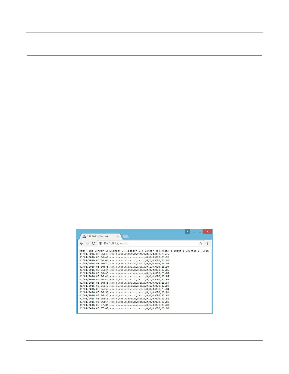
XW-210 WiFi™ Users Manual
6.5 LogFile
XW-210 logs information to log.txt. This log file is a text file stored in nonvolatile memory and will not be
lost due to power failure. The log files are stored in a circular buffer which writes from the beginning of
the allocated memory space to the end and then repeats from the beginning (over-writing the original
data). The nonvolatile memory is divided into 4-Kbyte sectors. Each time data gets erased to make room
for new data, a full sector (4-Kbytes) is erased at one time.
6.5.1 Data Log File – log.txt
This log file is user-configurable under the Logging setup tab, and stores real-world data such as
temperatures and events such as relay state changes (see Section 4.6: Logging Tab for more
information). It can be up to 512-Kbytes long and is stored using a comma separated value formatting
scheme.
Inputs, Relays, Vin, and Sensors will only be displayed if they are selected in the Logging setup tab. The
file is read by requesting the log.txt file from XW-210. For example, using the default IP address the
following command would be used to request the log file:
http://192.168.1.2/log.txt
File Format:
MM/DD/YYYY HH:MM:SS, Sensors 1-4, Relay 1, Input 1, Counter, Vin
Date and Time Format:
MM – Month (1-12)
DD – Day (1-31)
YYYY – Year (1970 - 2106)
HH – Hour in 24 hour time (0 -23)
MM – Minutes (0-59)
SS – Seconds (0-59)
Sample File:
The file can then be saved using the 'Save As...' option under the 'File' menu of the web browser. If the
TCP port has been changed (not port 80), the port will be required to read the file. For example, using
Xytronix Research & Design, Inc. Page 65
Page 66

Auxiliary Operations XW-210 WiFi™ Users Manual
the default IP address, and port 8000, the log file would be read as follows:
http://192.168.1.2:8000/log.txt
The log.txt file may be erased with the following command:
http://192.168.1.2/log.txt?erase=1
After erasing the file, it might be necessary to refresh the page.
Note: If the Control Password is enabled in the setup pages, the password will be required to access the
log file.
Page 66 Xytronix Research & Design, Inc.
Page 67
XW-210 WiFi™ Users Manual
6.6 Modbus/TCP
XW-210 can be controlled and monitored using Modbus/TCP protocol. This provides a standard means
of using XW-210 with devices and software from other manufacturers. This section is not a tutorial on
Modbus and it is assumed that the reader is already familiar with Modbus. Detailed Modbus information
can be found at http://www.modbus.org.
Note: Modbus communications are disabled whenever the Control Password is enabled. This is because
Modbus/TCP does not provide a mechanism for password protection. Make sure the Control Password
is disabled (default) and Modbus functionality is enabled on the Advanced Network.
XW-210 functions as a Modbus slave. Host devices, such as PLCs, open a connection with XW-210 on
port 502 (configurable under Advanced Network tab) and then send requests to read or set relay states,
read input states, or sensor values. When XW-210 receives a command, it will perform the desired
function and return a response.
The following sections provide an overview and explanation of Modbus operation.
6.6.1 XW-210 Modbus Function Code Summary
XW-210 supports the following function codes:
Code Name Modbus
Function
XW-210 Feature XW-210 Start Address
Hexadecimal Decimal
Read Coils 01 Relay 1 0x0000 0
Read Discrete Inputs 02 Input 1 0x0000 0
Read Analog Inputs 03 Vin 0x0010 16
Read Sensors 03 Sensors 1-4 0x0110-0x0116 272-278
Read Counters 03 Counter 1 0x0210 528
Write Single Coil 05 Relay 1 0x0000 0
Write Multiple Coils 15 Relay 1 0x0000 0
Pulse Coils 16 Relay 1 0x0310-0x0311 784-785
Multiple commands may be sent without closing and re-opening the connection, but if no data is
transferred for 50 seconds, the connection will time out and close. To keep the connection open, a read
request can be sent periodically.
XW-210 has two TCP sockets available for Modbus/TCP. This allows two connections to be open at one
time. Requests for more than two open connections will be rejected.
When errors occur, an error code is returned. Most Modbus client software will interpret this code in a
human readable form. The code is comprised of the original function code plus 0x80. For example, an
error during the read coils function 0x01 would return 0x81. Each error has a qualifying exception
number. The following are the possible exception codes and their meanings:
0x01 - Function code not supported (also when Modbus is disabled in the setup pages).
0x02 - Incorrect starting address/quantity of output combination.
Xytronix Research & Design, Inc. Page 67
Page 68
Auxiliary Operations XW-210 WiFi™ Users Manual
6.6.2 PLC Device Addressing
There are generally two schemes for accessing Modbus devices. The first is by specifying the Modbus
function code, memory type, and address. The second, sometimes called PLC addressing, requires only
the address.
Modbus protocol uses four different address ranges for discrete inputs, coils, input registers, and holding
registers. The function code determines the address range of the message. The following are common
function codes and their respective address ranges.
Code Name Modbus
Function
Coils (Read/Write) 01, 05, 15 Discrete 1-1000 1-10000
Discrete Inputs (Read only) 02 Discrete 1001-2000 10001-20000
Registers (Read only) 04 8-64 bits 3001-4000 30001-40000
Holding Registers
(Read/Write)
* Data types may be implemented at the discretion of the manufacturer. Address ranges may also over
lap. Discrete is a binary or boolean value, 1 or 0.
Function codes, memory types, and addresses can be converted to the PLC addressing equivalent using
the table below. To use the table, look up the row corresponding to the Modbus function code. Then take
the desired XW-210 feature address and add to it the address offset in the PLC address mode column.
Input Address + PLC Base Address = PLC Address
For example, to read discrete Input 2
Input Address 1
PLC Base address 1001
PLC Address 1002
Programming the PLC to read from 1002 will return the value of Input 2.
Code Name Modbus
Function
Read Coils 01 0 (Relay 1) Discrete Addr + 1 Addr + 1
Read Discrete Inputs 02 0 (Input 1) Discrete Addr + 1001 Addr + 10001
Read Holding
Registers
Write Coils 05 0 (Relay 1) Discrete Addr + 1 Addr + 1
Write Multiple Coils 15 0 (Relay 1) Discrete Addr + 1 Addr + 1
Write Multiple
Registers
03 16 (Vin) 32-bit float Addr + 4001 Addr + 40001
16 784-785 (Relay 1) 32-bit float Addr + 4001 Addr + 40001
03, 06, 16 8-64 bits 4001-5000 40001-50000
XW-210 Addresses Data Type PLC Address
272-278 (Sensors 1-4) 32-bit float Addr + 4001 Addr + 40001
528 (Counter 1) 32-bit float Addr + 4001 Addr + 40001
Data Type* PLC Address
Mode 485
Mode 485
PLC Address
Mode 584/984
PLC Address
Mode 584/984
For 32-bit numbers or floats, two registers must be read starting at the desired address, examples of
each are given for the applicable functions.
Page 68 Xytronix Research & Design, Inc.
Page 69
XW-210 WiFi™ Users Manual
6.6.3 XW-210 Full Address Table
The table below gives commonly used function codes, memory types, data sizes, and equivalent PLC
addresses for accessing the XW-210. The data size will be the same regardless of the addressing mode.
Function
Code
Read Relay 1
Write Relay 1
Read Input 1 State
Read Vin
Read Sensor 1
Read Sensor 2
Read Sensor 3
Read Sensor 4
Read Counter 1
Write Multiple Relays
Pulse Relay
01
05
02
03
03
03
03
03
03
15
16
Address
(Decimal)
0 Discrete 1 1
0 Discrete 1 1
0 Discrete 1001 10001
16 32-bit Float 4017 40017
272 32-bit Float 4273 40273
274 32-bit Float 4275 40275
276 32-bit Float 4277 40277
278 32-bit Float 4279 40279
528 32-bit int 4529 40529
0 8-bit 1 1
784 32-bit Float 4785 40785
Data Size PLC Address
Mode 485
PLC Address
Mode 584/984
Xytronix Research & Design, Inc. Page 69
Page 70
Auxiliary Operations XW-210 WiFi™ Users Manual
6.6.4 Read Coils - Modbus Function Code 01 (0x01)
Read the state of the relay.
Request
Start Address: 0x0000 (coil 1)
Coil Quantity: 0x0001 (1 coil)
Response
The XW-210 will respond to the request with a data field of one byte, each bit representing the coil
status. A '1' indicates the Output is ON. A '0' indicates that the Output is OFF.
Bit zero of the return value will be the state of the coil corresponding to the start address. For example, if
a start address of 0x0000 is used, bit zero will be the status of Relay 1.
Coil State Byte
Bit 7 6 5 4 3 2 1 Bit 0
X X X X X X X Relay 1
Errors
The sum of the start address and coil count cannot exceed the maximum coil count or an error response
will be returned.
The following are possible error responses.
Coil Read Error Function Code (1 byte): 0x81
Exception Codes (1 byte): 0x01 – Function code not supported.
0x02 – Incorrect combination of start address and quantity of Relays
Page 70 Xytronix Research & Design, Inc.
Page 71
XW-210 WiFi™ Users Manual
6.6.5 Read Discrete Inputs – Modbus Function Code 02 (0x02)
This function returns the state of the digital input.
Request
Start Address: 0x0000 (input1)
Input Quantity: 0x0001
The sum of the starting address and the quantity of coils must not be greater than 0x0001.
Response
The input state is indicated by bit zero of the status byte. A 1 indicates that the input is switched high ON.
A 0 indicates that the input switched low OFF. Bit zero of the return value will be the state of the coil
corresponding to the start address. For example, if a start address of 0x0000 is used, bit zero will be the
status of input 1.
Discrete Input State Byte
Bit 7 6 5 4 3 2 1 Bit 0
X X X X X X X Input 1
Errors
Input Read Error Function Code (1 Byte): 0x82
Exception codes (1 Byte): 0x01 – Function not supported.
0x02 – Incorrect combination of start address and input quantity.
Xytronix Research & Design, Inc. Page 71
Page 72

Auxiliary Operations XW-210 WiFi™ Users Manual
6.6.6 Read Sensors – Modbus Function Code 03 (0x03)
The Read Holding Registers function is used for the temperature and other Xytronix 1-wire sensors.
Request
32-bit sensor values are read from 16-bit register pairs. Consequently, senors addresses and registers
must be even numbers.
Vin Start Addresses
Start Address: 0x0010 (Vin)
Input Quantity: 0x0002
Temperature and Other Sensor Start Addresses
Start Address: 0x0110 (Sensor Input 1) to 0x0116 (Sensor Input 4)
Input Quantity: 0x0002 to 0x0008
Counter Start Addresses
Start Address: 0x0210 (Count 1)
Input Quantity: 0x0002
Response
32-bit floating-point values are returned, either as little-endian or big-endian numbers, depending on the
configuration in the Advanced Network tab.
With little-endian ordering, a temperature reading of sensor 1 (0x0110) would return 0x800042A2. The
least significant word would be 8000 hex and the most significant word would be 42A2. This hexadecimal
value converts to a temperature reading of 81.25 degrees.
If a temperature or other sensor is not installed, a value of 0xFFFFFFFF (NaN) is returned. Other inputs
will show measured values of the open circuits.
Errors
Sensor Read Error Function Code (1 byte): 0x83
Exception Codes (1 byte): 0x01 – Function not supported.
0x02 – Incorrect combination of start address and input quantity
Page 72 Xytronix Research & Design, Inc.
Page 73

XW-210 WiFi™ Users Manual
6.6.7 Write Single Coil – Modbus Function Code 05 (0x05)
Relays may be controlled one at a time.
Request
Start Address (2 bytes): 0x0000 (Relay 1)
Output Value (1 byte): 0x00 (OFF), 0xFF(ON)
Padding (1 byte): 0x00
Response
The response mirrors the requested state, 0x00 or 0xFF.
Errors
Single Coil Write Error Function Code (1 Byte): 0x85
Exception codes (1 Byte): 0x01 – Function not supported.
0x02 – Address out of range.
0x03 – Padding value.
Xytronix Research & Design, Inc. Page 73
Page 74
Auxiliary Operations XW-210 WiFi™ Users Manual
6.6.8 Write Multiple Coils - Modbus Function Code 15 (0x0F)
One byte can be written to set the state of all relays, each bit representing one relay.
Request
Relay states are controlled by specifying the start address of the first relay to be controlled, the count of
the relays to be affected, and the relay state byte.
A relay value of 0xFFFF would be used to turn ON all of the relays in the range or 0x0000 to turn them
OFF. In the above example, the relay value 0xFF would turn relay 1 ON.
Start Address (2 bytes): 0x0000 (Relays 1)
Output Quantity (2 bytes): 0x0001
Byte Count (1-2 bytes): 0x01
Relay Value (1 bytes): 0x0000 – 0x0001
Relay State Byte
Bit 7 6 5 4 3 2 1 Bit 0
X X X X X X X Relay 1
Response
The quantity value is returned.
Errors
Multiple Coil Write Error Function Code (1 Byte): 0x8F
Exception codes (1 Byte): 0x01 – Function not supported.
0x02 – Incorrect combination of start address and Relay quantity
0x03 – Byte count out of range.
Page 74 Xytronix Research & Design, Inc.
Page 75

XW-210 WiFi™ Users Manual
6.6.9 Write Multiple Registers – Modbus Function Code 16 (0x10)
The Modbus Write Multiple Registers function can be used to pulse the relays.
Request
The Modbus Write Multiple Registers function is used to pulse the relay(s) for a specified time. When the
XW-210 receives this command, it immediately turns the appropriate relay(s) ON (if not already on) and
starts the pulse timer.
The pulse time is specified using floating point format in the register value field and can range from 0.1
seconds to 86400 seconds (1 day). When the pulse time expires, the relay will be turned OFF. If a pulse
time command is sent with a value greater than 86400, the pulse timer will be set to 86400. If a pulse
time command is sent with a value less than 0.1, the pulse timer will be set to 0.1.
If any commands are sent to XW-210 (Modbus, XML or HTML) before the pulse timer has expired, the
pulse timer will be canceled immediately and the new command will be executed.
IEEE 754 floating point format is used for the pulse time. XW-210 may be configured for little-endian or
big-endian transmission. The endian-ness is configured in the Advanced Network tab. (See 2.4.3
Advanced Network Tab for more information.)
Start Address (2 bytes): 0x0310 (relay 1)
Register Quantity (2 bytes): 0x0002
Byte Count (1 byte): 0x04
Pulse Duration (4 bytes/relay): 0x3DCCCCCC – 0x47A8C000 (big-endian)
0xCCCC3DCC – 0xC00047A8 (little-endian)
Response
The request is acknowledged by responding with the register quantity that was requested.
Errors
Pulse Function code Error (1 Byte): 0x90
Exception codes (1 Byte): 0x01 – Feature not supported.
0x02 – Address quantity not an even number.
Incorrect combination of start address and relay count.
Xytronix Research & Design, Inc. Page 75
Page 76

Auxiliary Operations XW-210 WiFi™ Users Manual
6.7 Basic Scripts
BASIC (Beginners All-purpose Symbolic Instruction Code) is a computer programming language that has
been in use for many years. The XW-210 has an integrated BASIC interpreter for a simple BASIC script.
This provides a great deal of flexibility by allowing users to customize basic functions of the unit. The
interpreter only supports a small subset of the BASIC commands that are available for larger computers.
Some non-standard commands have been added, and some commands may function differently on the
XW-210 BASIC interpreter than on other platforms. The following is a short tutorial on the supported
BASIC functions.
Example scripts are available at www.controlbyweb.com. Contact customer support if further assistance
is required.
6.7.1 Structure
A BASIC script is written as a .txt file, which is then uploaded to the device using the Script setup tab.
The maximum script size is 4-Kbytes. Each line within the script contains a single statement. Line
numbers are not used.
Statements are not case sensitive; however, variables are.
IF THEN, FOR loops, and DO loops can only be nested up to 5 times per command. For those not
familiar with nesting, the following is an example of nested FOR loops:
FOR a = 0 to 100
FOR b = 0 to 100
NEXT b
NEXT a
Every program must end with an END statement. Subroutines would then follow after the END
statement, if required. The last line of the script should be left blank.
6.7.2 Line Format
Every line follows the same format. The basic format is:
statement (variable) (=, <, >, <=, >=, <>) (expression) (THEN)
The fields in parentheses are optional depending on the statement. Spaces must be used between
all statements, numbers, variables, operators, expressions, etc. Multiple spaces are invalid.
Comments may be inserted, but must begin with an apostrophe. All text on a line after the apostrophe is
ignored.
Examples:
LET a=1 'this will return an error because of insufficient spacing
LET a = 1 'this is valid
LET a = 1 'this will return an error because of too many spaces
Only a single variable or literal is allowed on the left side of any operator. The following example is
incorrect and will return an error. The error occurs because there is more than a single value to the left of
the comparison operator (a + 2 is to the left of =).
IF a + 2 = 3 THEN 'this will return an error
To fix the above line, replace 'a + 2'. One of the following options may be used:
LET b = a + 2
IF b = 3 THEN
...
END IF
Page 76 Xytronix Research & Design, Inc.
Page 77

XW-210 WiFi™ Users Manual
6.7.3 Supported Statements
The following are the statements supported by the ControlByWeb™ BASIC interpreter.
LET
The LET statement assigns a variable a value. The format is:
LET (variable) = (expression)
IF THEN, ELSE, END IF
The IF THEN statement tests the truth of a condition. The ELSE statement defines a second function if
the condition is found false. In other words, if the condition is true, then a function is performed. If it is not
true, a second function may be performed. The second function may or may not be necessary depending
on the application. The IF THEN (ELSE) statement must always be followed with an END IF statement.
The format is:
IF (variable) (=, <, >, <=, >=, <>) (expression) THEN
(Function 1)
ELSE
(Function 2)
END IF
Note: In most BASIC interpreters, 'Function 1' (see above) may be placed after the THEN statement.
This interpreter requires 'Function 1' to be put on the following line.
FOR TO, NEXT
The FOR TO statement loops a section of code a predefined number of times. The NEXT statement
always follows the section of code to be looped. The format is:
FOR (variable) = (expression) TO (expression)
(code to be looped)
NEXT (variable)
DO WHILE, LOOP
The DO WHILE statement loops a section of code while a condition is found true. The LOOP statement
always follows the section of code to be looped. Note that if the condition is omitted, the code will be
looped without end. The format is:
DO WHILE (variable) (=, <, >, <=, >=, <>) (expression)
(code to be looped)
LOOP
Example:
let t0 = 100
do while t0 > 0
' wait
loop
LOG
The LOG statement causes the device to log data according to the settings specified under the Logging
setup tab.
Note: In order to log, logging must be enabled in the Logging setup tab.
The format is: LOG
Xytronix Research & Design, Inc. Page 77
Page 78

Auxiliary Operations XW-210 WiFi™ Users Manual
EMAIL
The EMAIL statement causes the device to send an email of the same format as that generated by other
status change and alarm conditions. The event that triggered the email is given, followed by the I/O or
Sensor that you want to email. The format is:
EMAIL (feature state – relay1, input1, tempX) 'X represents the feature number such as temp2
Examples:
EMAIL 'Status email sent to addresses listed under Network tab.
...or...
EMAIL relay1 'Sends state change message to emails setup in I/O tab.
...or...
EMAIL input1 'Input state change message to emails setup in I/O tab.
...or...
EMAIL temp2 'Temp alarm message sent to recipients in the Sensors tab.
END
The END statement ends the main body of code.
CALL
The CALL statement is found within the main body of code, but requires the interpreter to skip to a
subroutine found at the end of the program. After the subroutine is finished, the interpreter returns to the
line immediately following the CALL statement. The format is:
CALL (name of subroutine)
SUB, END SUB
The SUB statement defines the beginning and name of a subroutine. The END SUB statement defines
the end of the respective subroutine. Subroutine names can be up to 20 characters long and are case
sensitive. The SUB and END SUB statements always must follow the END statement. The format is:
END
'*** Subroutines Go Here ***
SUB (name of subroutine)
(contents of subroutine)
END SUB
SUB (name of subroutine)
(contents of subroutine)
END SUB
REM or '
The REM or apostrophe ( ' ) statement designates remarks made by the programmer. The interpreter will
disregard any characters on the line following these statements.
PRINT
The PRINT statement displays a variable or message to the display. The PRINT statement is only
available for the PC version of the BASIC interpreter. The device will not recognize the command since it
does not have an operator display. The format is:
PRINT (variable) 'show variable value to screen
PRINT "(message)" 'show '(message)' to screen
Page 78 Xytronix Research & Design, Inc.
Page 79

XW-210 WiFi™ Users Manual
6.7.4 User-Defined Variables
Two types of variables are available for use in the ControlByWeb™ BASIC interpreter, user-defined
variables, and predefined variables.
Up to 10 user variables may be initialized. These must be single character, lower case letters.
a, b, c, d, e, f, g, h, i, j
They are always global and stored internally as floating point numbers. Variables are defined using the
LET statement.
Examples:
Let b = 5 'variable b will be set to 5
Let d = b + 2 'variable d will be set to 7
6.7.5 Predefined Variables
The following are useful predefined variables for the ControlByWeb™ BASIC interpreter. These are
useful for accessing internal values and features states.
6.7.5.1 Timer Variables
Six timers are available for use in BASIC scripts.
t0, t1, t2, t3, t4, t5
Timers can be set to any positive integer (or 0) by using the LET statement. As soon as a value is
assigned to a timer, it will begin to count down immediately by decrementing one count every 100 ms
until it reaches zero.
Examples:
Let t3 = 1500 'set timer 3 to 150 seconds
Let t1 = 0 'disable time 1
6.7.5.2 Relay Variables
Relay variables represent the state of the relays and can be used to change the state of the relays.
Remote relays can also be controlled, but not read. The following variables are available.
relay1 'relay 1
rmt_relay1 'remote relay 1
rmt_relay2
Note: Commands can be sent to remote relays, but the states of those relays cannot be read.
Consequently, remote relays should not be used in safety or security-critical applications.
Relay outputs can be turned ON, turned OFF, pulsed, toggled, or read in BASIC scripts. The LET
statement is used to set the output state. The state options available are:
0 – turn relay off
1 – turn relay on
2 – pulse relay
5 – toggle relay
The pulse time is specified in the Relay setup tab.
Examples:
Let relay1 = 1 'turn on relay 1
Let relay1 = 0 'turn off relay 1
Let relay1 = 2 'pulse relay 1
Let relay1 = 5 'toggle relay 1
Let a = relay2 'read the state of relay 2, state will be 0 or 1
Xytronix Research & Design, Inc. Page 79
Page 80

Auxiliary Operations XW-210 WiFi™ Users Manual
6.7.5.3 Input Variables
The digital input states can be read in BASIC scripts.
input1 'digital input 1
Example:
Let a = input1 'sets 'a' equal to value of input 1
6.7.5.4 Counter Variables
The input counter can be read in BASIC scripts.
count1 'input 1 counter
Example:
If count1 > 5000 Then 'If input counter 1 is greater than 5000 then
End If
Let relay1 = 1 'turn output 1 on
6.7.5.5 Vin Variable
The vin voltage can be read in BASIC scripts.
vin 'Read the Vin voltage
Example:
If vin > 10 Then 'If Vin is greater than 10 volts then
Else
End If
Let relay1 = 2 'Pulse output 1, otherwise
Let relay1 = 0 'output1 will be off
6.7.5.6 Temperature/Other Sensor Variables
Each temperature sensor or other Xytronix 1-wire sensor can be read in BASIC scripts.
temp1 'temp or other sensor 1
temp2 'temp or other sensor 2
…
temp4 'temp or other sensor 4
Example:
If temp2 >= 80 Then 'If temperature sensor reads greater than 80
Let relay2 = 1 'Turn on relay 2
End If
' degrees, then
6.7.5.7 Date and Time Variables
The variables 'time' and 'date' are predefined, read only variables that store the current date and time.
They can be used to schedule events and activities, such as sending emails, reading temperature, or
setting Outputs. The date uses the mm/dd/yyyy format. Clock time is formatted as hh:mm:ss (24-hour
clock).
Example:
If date = 01/01/2014 Then
If time > 12:30:00 Then
Let relay2 = 1
Let relay3 = 0
End If
End If
Note: Current date and time can only be set in the Date/Time tab.
Page 80 Xytronix Research & Design, Inc.
Page 81

XW-210 WiFi™ Users Manual
6.7.5.8 Event Variables
Data and time variables can be used to execute script events.
Up to five date variables are available.
ed1 'event date variable 1
… 'ed2, ed3, ed4
ed5 'event date variable 5
The value assigned to event variables should be in the format mm/dd/yyyy. The event date variables
store the number of days that have passed since January 1, 1970.
Event time variables may be used in math expressions as well as comparison statements.
Time variables have a similar naming convention.
et1 'event time variable 1
... ' et2, et3, et4
et5 'event time variable 5
Event time variables are declared in the format hh:mm:ss in 24-hour time. The event time variables store
the number of seconds from the beginning of the day.
Event date and event time variables of the same number are linked. If the event time variable is
incremented more than the number of seconds in a day (86400 seconds), the variable is reset to 0 and
the event date variable is incremented by one. For example, if et3 rolls over to zero, ed3 will be
incremented.
The following script example demonstrates defining the event variables and comparing it to the current
date and time. Assume current time is April 10, 2010 at 1:30 AM and the event should occur in one hour
and every hour thereafter.
Example:
Let a = 1
Let ed1 = 04/10/2010 'sets the event date to April 10,
Let et1 = 02:30:00 'sets the event time to 2:30
Do While a <> 0
If ed1 >= date Then 'Tests event date versus current date.
If et1 >= time Then 'Tests event time versus current time.
Let et1 = et1 + 3600 'Increments the event time by one hour
Print "Event" 'Event to occur
End If
End If
Loop
End
'2010.
'(in seconds).
6.7.6 Registers
Registers are similar to general purpose variables and can be used in the same manner. The difference
between general purpose variables and registers is that external registers can be accessed by the user
through a web browser and modified while the script is running. Scripts can use registers as a method of
retrieving user input.
register1 'register variable 1
… 'register2, register3
register4 'register variable 4
The following example demonstrates this by creating a script that will turn Remote Relay 1 ON if
register1 equals 1 and OFF otherwise.
Xytronix Research & Design, Inc. Page 81
Page 82

Auxiliary Operations XW-210 WiFi™ Users Manual
Example:
Do
If register1 = 1 Then
Let rmt_relay1 = 1
Else
Let rmt_relay1 = 0
End If
Call delay
Loop
End
SUB delay
Let t1 = 10
Do While t1 > 0
Loop
End Sub
Registers can also be used to show numeric values, such as a count down timer. If the register is any
other value than 1 or 0, the value will be displayed in the Status 2 column. See Section 4.11: Control
Page Setup for instructions on configuring Registers for visibility on the Control Page.
The following code will show a count down from 10 seconds and automatically restart. The refresh rate
for the control page is set to 3 seconds, so the countdown may appear to jump.
Example:
let t0 = 10 'Initialize variables and start timer
let register1 = 10
'Main Loop
Do
if t0 = 0 'when timer reaches 0 decrement counter
let register1 = register1 - 1
let t0 = 10
end if
if register1 < 0 'restart when counter reaches zero
end if
loop
end
let register1 = 10
register1 can be set and cleared by entering the following requests into a web browser or by configuring
on and off buttons to appear on the Control Page for register1:
http://192.168.1.2/state.xml?register1=1
http://192.168.1.2/state.xml?register1=0
6.7.7 Testing and Debugging
A copy of the BASIC interpreter for Windows is available on www.controlbyweb.com for testing and
debugging. The XW-210 will only acknowledge errors as it runs. This means that if a path of the script is
not encountered, errors may still exist. The Windows version of the interpreter, however, will check for
errors before the script is run.
The PRINT function is available for use with the Windows version of the BASIC interpreter. The
interpreter on the device, however, will not recognize this command.
Note: The script will be restarted by submitting any of the setup pages or by power cycling the unit.
The “MISSING END OF LINE” error may be caused by misspelled names or a program that is too long.
4096 bytes of memory is reserved for BASIC scripts. Each text character, space, punctuation mark, tab,
or carriage return uses one byte. If the script is too long, the script will be truncated and will not function
as desired.
Page 82 Xytronix Research & Design, Inc.
Page 83
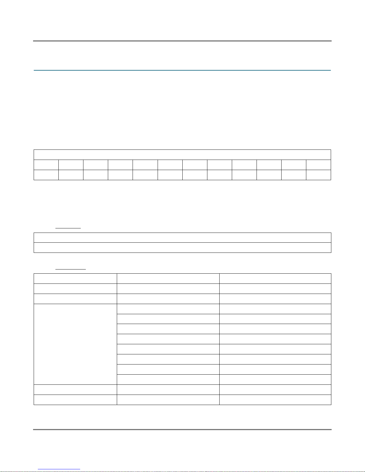
XW-210 WiFi™ Users Manual
6.8 Network Discovery
XW-210 has implemented a network discovery and provisioning protocol to aid in accessing the device.
With this protocol, a user may connect the device to a network without knowing the IP address, search
and identify the IP address, query basic information and if not yet configured send the desired network
and remote services configurations. This feature can be utilized in the latest versions of the Android and
iOS apps.
The network discovery protocol listens for specific requests on UDP port 65431 sent to the IP broadcast
address 255.255.255.255. All requests must have the proper header and, when applicable, the correct
MAC address. This header is the first 12 bytes of all messages and is simply the string 'ControlByWeb'.
Header
C o n t r o l B y W e b
0x43 0x6f 0x6e 0x74 0x72 0x6f 0x6c 0x42 0x79 0x57 0x65 0x62
6.8.1 Initial Contact
The initial contact request is sent to discover ControlByWeb devices on the network. It is recommended
to send this message multiple times in environments where many ControlByWeb devices are present
due to potentially lost traffic where collisions occur as UDP does not guarantee deliver of packets.
Request:
Header (12 bytes) ASCII String ControlByWeb
Message ID (1 byte) Initial Contact Request 0x00
Response:
Header (12 bytes) ASCII String ControlByWeb
Message ID (1 byte) Initial Contact Response 0x01
MAC Address (6 bytes) Binary version 0x00 0x0c 0xc8 0x00 0x00 0x00
Device Info (2 bytes) Bit[15-7] Reserved 0b0
Bit 6 – Mode 0b0=Station, 0b1=AP
Bit 5 – Reserved 0b0
Bit 4 – Remote Services Status 0b0=Disconnected, 0b1=Connected
Bit 3 – DHCP Status 0b0=Waiting, 0b1=Success
Bit 2 – Remote Services Enabled 0b0=Disabled, 0b1=Enabled
Bit 1 – DHCP Enabled 0b0=Disabled, 0b1=Enabled
Bit 0 – Configuration Allowed 0b0=Not Allowed, 0b1=Allowed
Model Code (2 bytes) 0x00 0x2A=XW-210
IP Address (4 bytes) Network endianness 0xc0 0xa8 0x01 0x02 (192.168.1.2)
Xytronix Research & Design, Inc. Page 83
Page 84
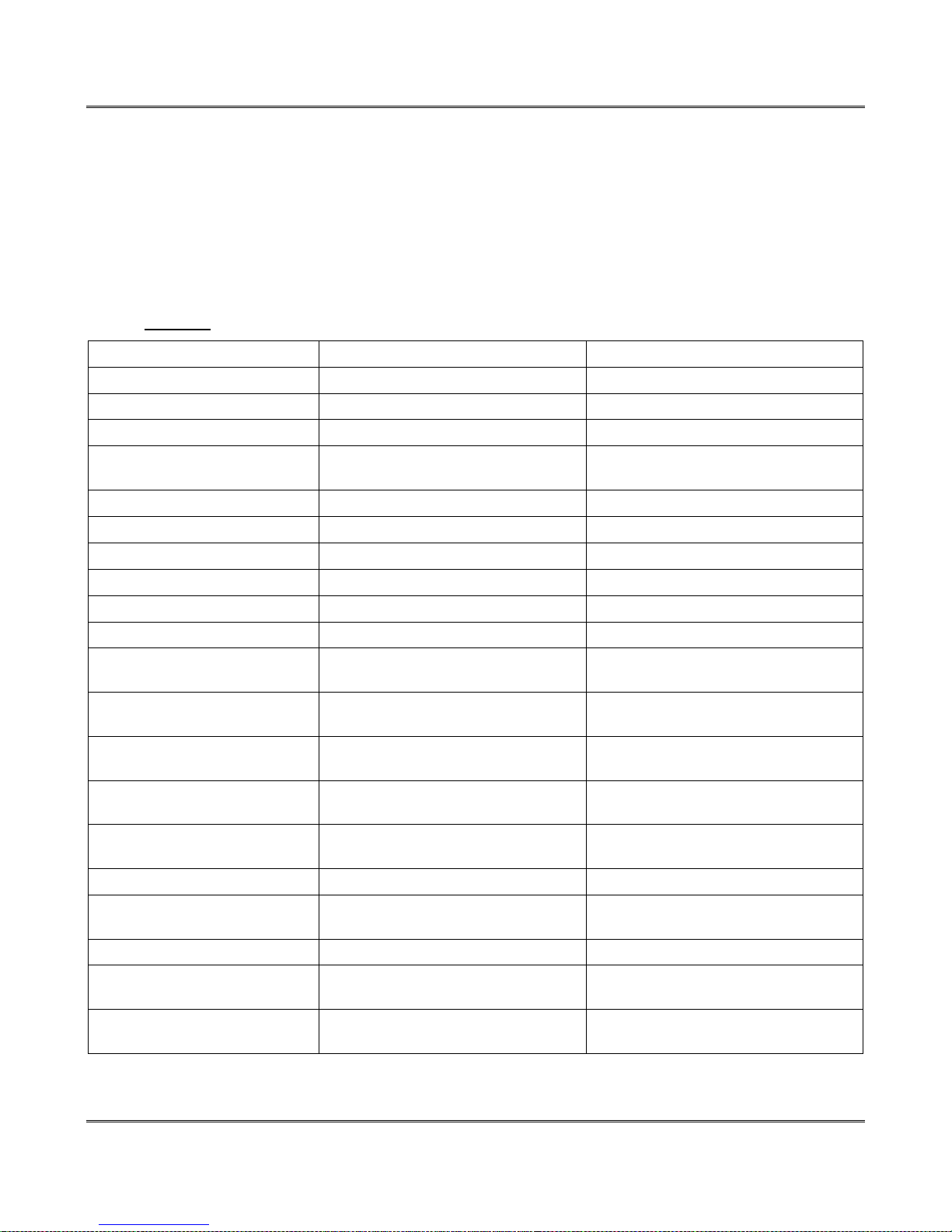
Auxiliary Operations XW-210 WiFi™ Users Manual
6.8.2 Setup Information
The Setup Information request allows the device to receive IP network, remote services and WiFi
network configuration data that it should use. Once this request is properly received, the device will apply
the settings and reboot. There are two variants of this request, one has message ID 0x03 and the other
has message ID 0x06. The only difference in these requests is message ID 0x06 includes fields for WiFi
SSID, security and password.
Once the device has received this command or after the user has configured the device through the
web-pages, this request will be ignored and will return an error. The only way to re-enable this request, is
to reset the device to factory defaults, or re-associate the device to a WiFi network via WPS.
Request:
Header (12 bytes) ASCII String ControlByWeb
Message ID (1 byte) Setup Information request 0x03 -or- 0x06
MAC Address (6 bytes) Binary version 0x00 0x0c 0xc8 0x00 0x00 0x00
DHCP (1 byte) Enable DHCP 0x00=Disabled, 0x01=Enabled
Enable Remote Services (1
byte)
Token (32 bytes) ASCII String, no null terminator ''xxxxxxxxxxxxxxxxxxxxxxxxxxxxxxxx”
IP Address (4 bytes) Network endianness 0xc0 0xa8 0x01 0x02 (192.168.1.2)
Subnet (4 bytes) Network endianness 0xff 0xff 0xff 0x00 (255.255.255.0)
Gateway (4 bytes) Network endianness 0xc0 0xa8 0x01 0x01 (192.168.1.1)
Primary DNS (4 bytes) Network endianness 0x08 0x08 0x08 0x08 (8.8.8.8)
Alternate DNS (4 bytes) Not used by the XW-210 0x08 0x08 0x04 0x04 (8.8.4.4)
Remote Services Version (1
byte)
Remote Services port number
(1 byte)
Remote Services Connection
Interval (2 bytes)
Remote Services uses SSL (1
byte)
Certificate retrieval port number
(2 bytes)
Remote Services host Null terminated ASCII string devices.controlbyweb.cloud
Remote Services Connection
String
WiFi Security option (1 byte) Message ID 0x06 only 0x00=none, 0x01=WEP, 0x02=WPA(2)
SSID Null terminated ASCII string
Password Null terminated ASCII string
Enable Remote Services 0x00=Disabled, 0x01=Enabled
Specify protocol version 0x01=1.0, 0x02=2.0
Port Remote Services server is
listening on (Network Endianness)
Time in minutes between connection
attempts and pushing state.xml
Only applicable to Remote Services
Version 2.0
Port used to pass token information
to retrieve certificates
Null terminated ASCII string
(message ID 0x06 only)
(message ID 0x06 only)
0x1f 0x40 (8000)
0x00 0x01 (1 minute)
0x00=No SSL, 0x01=Use SSL
0x01 0xbb (443)
Page 84 Xytronix Research & Design, Inc.
Page 85
XW-210 WiFi™ Users Manual
Successful Response:
Header (12 bytes) ASCII String ControlByWeb
Message ID (1 byte) Setup successful response 0x04
MAC Address (6 bytes) Binary version 0x00 0x0c 0xc8 0x00 0x00 0x00
Error Response:
Header (12 bytes) ASCII String ControlByWeb
Message ID (1 byte) Command not recognized response 0x05
MAC Address (6 bytes) Binary version 0x00 0x0c 0xc8 0x00 0x00 0x00
Xytronix Research & Design, Inc. Page 85
Page 86
Appendix A: Specifications XW-210 WiFi™ Users Manual
Appendix A: Specifications
Wireless Specifications
Network Standards: IEEE 802.11b/g/n
Frequency Band 2.412 – 2.462 GHz
Wi-Fi Security Standards Open, WEP, WPA, WPA2
Network Settings: DHCP or Static
Wireless Range Up to 250ft (typical for Wi-Fi devices) depends on environment
RF Output Power (typ) 14dBM (802.11b/g), 12dBM (802.11n)
Antenna: External, 2.4 GHz, 50Ω, omni directional, 1/4 wavelength,
gain: ≤ 2.1dBi. With articulated reverse SMA connector.
Operation
Provisioning: Via internal web server (no cables or PC utilities needed)
Access Point: Yes, push button activated (setup via web page)
WPS: Yes, push button activated (Wi-Fi Protected Setup)
Connectivity: Always connected
Remote Server: ControlByWeb's X-600™ or cloud-based server
Remote Relays: Control relays on other ControlByWeb™ products
Polling: state.xml (web-server is always active)
Power Requirements
Input Voltage: 9-28 VDC
Current: See table below for typical values at 25°C
Test Conditions 9VDC 12VDC 24VDC
AP Mode
relay Off and input Off
Attempting to connect to AP
relay Off and input Off
Connected to AP with network traffic
relay Off and input Off
Connected to AP with network traffic
relay On and input Off
Connected to AP with network traffic
relay Off and input On
Connected to AP with network traffic
relay On and input On
Push Buttons
Button 1: Force access-point mode
Button 2: Activate WPS mode
Relay Contacts
Load Type: General purpose
Contact Form: SPDT (form C)
Contact Material: Silver Nickel
Max Voltage: 277 VAC (general purpose)
30 VDC (NC contact, resistive)
68mA 51mA 31mA
68mA 52mA 36mA
65mA 50mA 28mA
185mA 140mA 72mA
75mA 57mA 31mA
188mA 143mA 75mA
Page 86 Xytronix Research & Design, Inc.
Page 87

XW-210 WiFi™ Users Manual
Max Current: 12A
Electrical Life: 100K cycles, typical @ full-rated load (higher with smaller load)
Mechanical Life: 10M cycles, typical
Environmental Rating: Over voltage Category II, Pollution Degree 2
Control Options: On/Off or Pulsed
Pulse Timer Duration: 100ms to 86400 Seconds (1-day)
Digital Input
Number of Inputs: 1
Minimum Pulse Time (high or low): 25mS
Input Current (Iin): 950uA @ 4V, 8.5mA @ 26V
Isolation (Viso): 1,500 Vrms
Reverse voltage (Vr): 6V max
Vin: 28V (max)
Vin Hi: 4V (min)
Vin Lo: 1.5V (max)
Input counter: 32-bit floating-point
1-Wire Sensor Input
Maximum number of sensors: 4
Works with digital “1-wire” thermometer probes
Interchangeable, no calibration needed
Dallas Semiconductor DS18B20 digital 1-wire thermometer
Available in bare or encapsulated versions
Also works with ControlByWeb™ wall-mount humidity sensors and other Xytronix 1-wire sensors.
Measurement Range: -55°C-to 125°C (-67°F to 257°F)
Accuracy: +/-0.5°C from -10°C to +85°C.
Maximum cable length: 600 feet maximum cable length
LED Indicators (4)
Green: Power On
Yellow: Relay On, Input On, Link
Configuration
Celsius/Fahrenheit: User configurable
Temperature Reports: Interval
Switch Status Reports: Interval, on state change, or both
Report Rate: User configurable
Email alerts
Email Alerts: Configurable, up to 8-addresses
Encrypted Email Alerts: Yes
Temperature Alerts: High or low temperature
Input Status Alerts: Input on, input off, or input change
Real-Time Clock
Manual or NTP (Network Time Protocol) setup, (not battery backed)
NTP sync configurable for once, daily, weekly or on power-up
Automatic daylight savings adjustment
Xytronix Research & Design, Inc. Page 87
Page 88

Appendix A: Specifications XW-210 WiFi™ Users Manual
Logging
Stored in non-volatile flash memory
Circular buffer 512-Kbytes (16000 to 32512 log entries depending on configuration)
Scripts
Implement special or custom features with a BASIC script
Max size 4-Kbytes
Environmental
Indoor use or NEMA-4 protected location
Altitude: up to 2000m
Operating Temperature: -40ºC to 65.5ºC (-40ºF to 150ºF)
Storage Temperature: -40ºC to 85ºC (-40ºF to 185ºF)
Humidity: 5-95%, non-condensing
Mechanical
Size: 1.41 x 3.88 x 3.1 in. (35.7 x 98.5 x 78 mm), (not including connector)
Weight: 5.4 oz (154 g), (including connectors and antenna)
Certifications
FCC ID: 2AE4Z-XWD002
FCC 47CFR15 (Class B)
IEC CISPR 22, CISPR 24
EN55024 ITE Immunity (2010)
EN55022 Emissions (2010)
IC: 21441-XWD002
Page 88 Xytronix Research & Design, Inc.
Page 89

XW-210 WiFi™ Users Manual
Appendix B: Trademark and Copyright Information
This document is Copyright ©2016 by Xytronix Research & Design, Inc. All rights reserved.
XW-210™, WebRelay™, ControlByWeb™, and Xytronix Research & Design™ are trademarks of
Xytronix Research & Design™, Inc. 2005-2017.
All other trademarks are the property of their respective owners.
All parts of this product and design including but not limited to firmware, hardware design, schematics,
PCB layout, concept, graphics, users manual, etc., are property of Xytronix Research & Design, Inc.
©2005-2017. XW-210™ may not be copied or reverse-engineered.
No part of this manual may be reproduced or transmitted in any form or by any means, electronic or
mechanical, including photocopying or scanning, for any purpose other than the personal use by the
purchaser of this product. Xytronix Research & Design, Inc., assumes no responsibility for any errors that
may appear in this document.
Whereas reasonable effort has been made to make the information in this document as useful and
accurate as possible, Xytronix Research & Design, Inc. assumes no responsibility for the application,
usefulness, or completeness of the information contained herein. Under no circumstance will Xytronix
Research & Design, Inc. be responsible or liable for any damages or losses including direct, indirect,
special, incidental, or consequential damages or losses arising from either the use of any information
contained within this manual or the use of any products or services referenced in this manual.
Xytronix Research & Design, Inc. reserves the right to change any product’s features, specifications,
documentation, warranties, fee schedules, and conditions at any time and without notice.
Xytronix Research & Design, Inc. Page 89
Page 90

Appendix C: Warranty XW-210 WiFi™ Users Manual
Appendix C: Warranty
This Xytronix Research & Design, Inc. product is warrantied against defects in material and workmanship
for a period of five years from the date of shipment. During the warranty period, Xytronix Research &
Design, Inc. will, at its option, either repair or replace products that prove to be defective. This warranty is
extended to the original purchaser of the equipment only.
For warranty service or repair, customer must contact Xytronix Research & Design, Inc. technical support
([email protected]) and obtain a Return Authorization number (RA#). Before issuing an RA#,
a support technician will work with customer to try to resolve the issue without returning the product. If
technician determines that product must be returned for service an RA# will be issued. Next, the product
must be properly packaged and returned to Xytronix Research & Design, Inc. with the RA# clearly
marked on the package. The purchaser shall prepay all charges for shipping to Xytronix Research &
Design, Inc. For warranty repairs of products less than one year old, Xytronix Research & Design, Inc.
will pay the shipping charges to return the product to the purchaser as long as the product is shipped
within the continental United States. If the product is shipped outside of the continental United States or
the product was shipped more than one year earlier, the purchaser shall pay all shipping charges, duties,
and taxes.
Limitation
The foregoing warranty shall not apply to defects or damage resulting from improper use or misuse,
unauthorized repair, tampering, modification, improper connection, or operation outside the
electrical/environmental specifications for the product. Further, the warranty does not cover Acts of God,
such as fire, flood, hurricanes, and tornadoes. This warranty does not cover damage to property,
equipment, direct, indirect, consequential, or incidental damage (including damage for loss of business
profit, business interruption, loss of data, and the like) arising out of the use or misuse of this product.
UNDER NO CIRCUMSTANCES WILL THE LIABILITY OF XYTRONIX RESEARCH & DESIGN, INC. TO
THE PURCHASER OR ANY OTHER PARTY EXCEED THE ORIGINAL PURCHASE PRICE OF THE
PRODUCT, REGARDLESS OF THE FORM OF THE CLAIM. No other warranty is expressed or implied.
Xytronix Research & Design, Inc. specifically disclaims the implied warranties or merchantability and
fitness for a particular purpose. Some jurisdictions may not allow the exclusion of limitation of liability for
consequential or incidental damage.
Page 90 Xytronix Research & Design, Inc.
Page 91

XW-210 WiFi™ Users Manual
Appendix D: FCC Statement
This device complies with Part 15 of the FCC Rules. Operation is subject to the following two conditions:
1. This device may not cause harmful interference.
2. This device must accept any interference received, including interference that may cause
undesired operation.
Warning
This equipment has been tested and found to comply with the limits for a Class B digital device, pursuant
to part 15 of the FCC Rules. These limits are designed to provide reasonable protection against harmful
interference in a residential installation. This equipment generates, uses and can radiate radio frequency
energy and, if not in-stalled and used in accordance with the instructions, may cause harmful
interference to radio communications. However, there is no guarantee that interference will not occur in a
particular installation. If this equipment does cause harmful interference to radio or television reception,
which can be determined by turning the equipment off and on, the user is encouraged to try to correct the
interference by one or more of the following measures:
- Reorient or relocate the receiving antenna.
- Increase the separation between the equipment and receiver.
- Connect the equipment into a relay on a circuit different from where the receiver is connected.
- Consult the dealer or an experienced radio/TV technician for help.
Notice
Changes or modification not expressly approved by the party responsible for compliance could void the
user’s authority to operate the equipment.
RF Exposure Information
This equipment complies with the FCC RF radiation exposure limits set forth for an uncontrolled
environment. The antennas used with this transmitter must be installed to provide a separation distance
of at least 20cm from all persons and must not be located or operating in conjunction with any other
antenna or transmitter.
Canadian License-Exempt Radio Apparatus (RSS-GEN)
This device complies with Industry Canada license-exempt RSS standard(s). Operation is subject to the
following two conditions: (1) this device may not cause interference, and (2) this device must accept any
interference, including interference that may cause undesired operation of the device.
Le présent appareil est conforme aux CNR d'Industrie Canada applicables aux appareils radio exempts
de licence. L'exploitation est autorisée aux deux conditions suivantes : (1) l'appareil ne doit pas produire
de brouillage, et (2) l'utilisateur de l'appareil doit accepter tout brouillage radioélectrique subi, même si le
brouillage est susceptible d'en compromettre le fonctionnement.
Under Industy Canada regulations, this radio transmitter may only operate using an antenna of a type
and maximum (or lesser) gain approved for the transmitter by Industry Canada. To reduce potential radio
interference to other users, the antenna type and its gain should be so chosen that the equivalent
isotropically radiated power (eirp) is not more than that necessary for successful communication.
Xytronix Research & Design, Inc. Page 91
Page 92
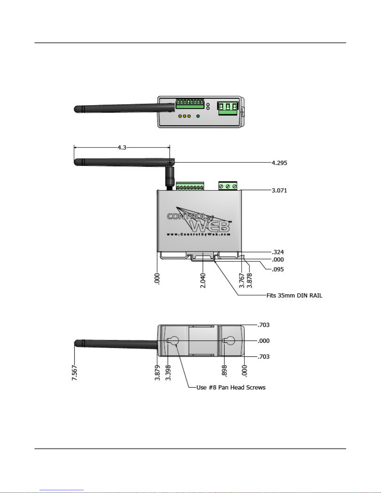
Appendix E: Mechanical Dimensions XW-210 WiFi™ Users Manual
Appendix E: Mechanical Dimensions
Page 92 Xytronix Research & Design, Inc.
 Loading...