

Page 1
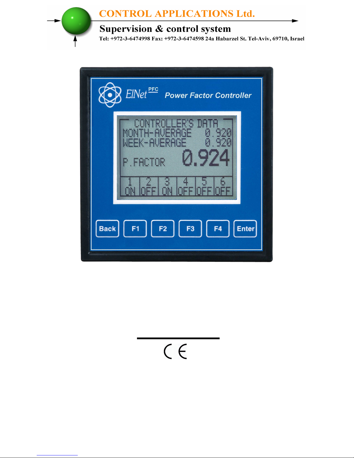
PFCElnet
Power Factor Controller
Rev. 1.4
Page 2

- 2 -
Table of Contents
CHAPTER 1 – Electrical Wiring
.........................................3
1.1 Electrical Connections................................................3
1.2 Electrical Wiring Diagrams........................................5
1.3 Test Relays Screen.......................................................8
CHAPTER 2 – Power Factor Controller......................................10
2.1 General Information....................................................10
2.2 Controller's Data Screen.............................................11
2.3 Voltage, Current, Hz....................................................12
2.4 Power Factor, THD......................................................12
CHAPTER 3 – Power Factor Controller Settings..........................14
3.1 Single \ Three Phase modes..........................................14
3.2 Transformers Ratio.......................................................15
3.3 Vital Settings..................................................................17
3.4 Non Vital Settings..........................................................21
3.5 Working Range..............................................................23
Page 3
- 3 -
CHAPTER 1 – Electrical Wiring
1.1. Electrical connections
All Connections, except those to the CT core of the ElNet PFC
Power Factor Controller are made via terminal connector plugs.
Recommended max tightening torque for the connector screws is
0.5 Nm.
The CT cores of the ElNet PFC Power Factor Controller are
located externally on the rear of the instrument and the lead from
the leg of the external Current Transformer must pass through in
the correct direction.
NOTE!
Ensure all the connections to the leads of the current
transformer wiring are secure and there is no mechanical
strain on the wire. The cross section of the leads to the
Current transformer must be compatible with the power of
the current transformer. We recommend a power transformer
with at least 3VA and the length of the wiring of the
transformer should not exceed 5m.
Page 4
- 4 -
1. Insert the lead from side “K” of the Current Transformers of
Line 1 through the hole marked "I1" – "K" of the ElNet PFC
Power Factor Controller.
NG
2. Repeat the procedure for Line 2 and Line 3 ("I2""I3"/"K").
3. Connect the rest of the connections to the ElNet PFC Power
Factor Controller by means of terminal connector plugs.
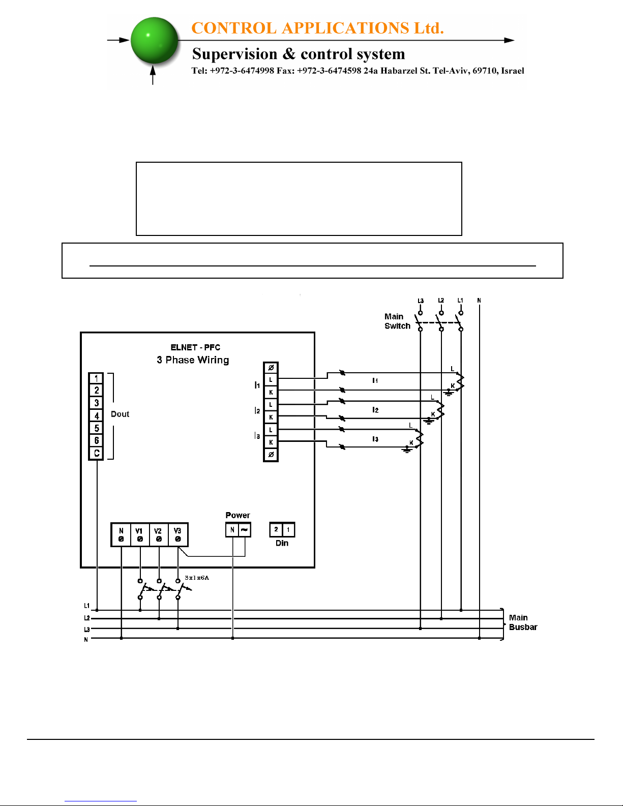
All Rear Panel connections are according to the
wiring diagram (See Figures 1.1, 1.2) and are easy to
follow.
WARNING!
Never allow an open circuit between "K" & "L" of the
Current Transformers.
Page 5
- 5 -
1.2. Electrical Wiring Diagrams
Figure 1.1 – Three Phase Electrical wiring diagram
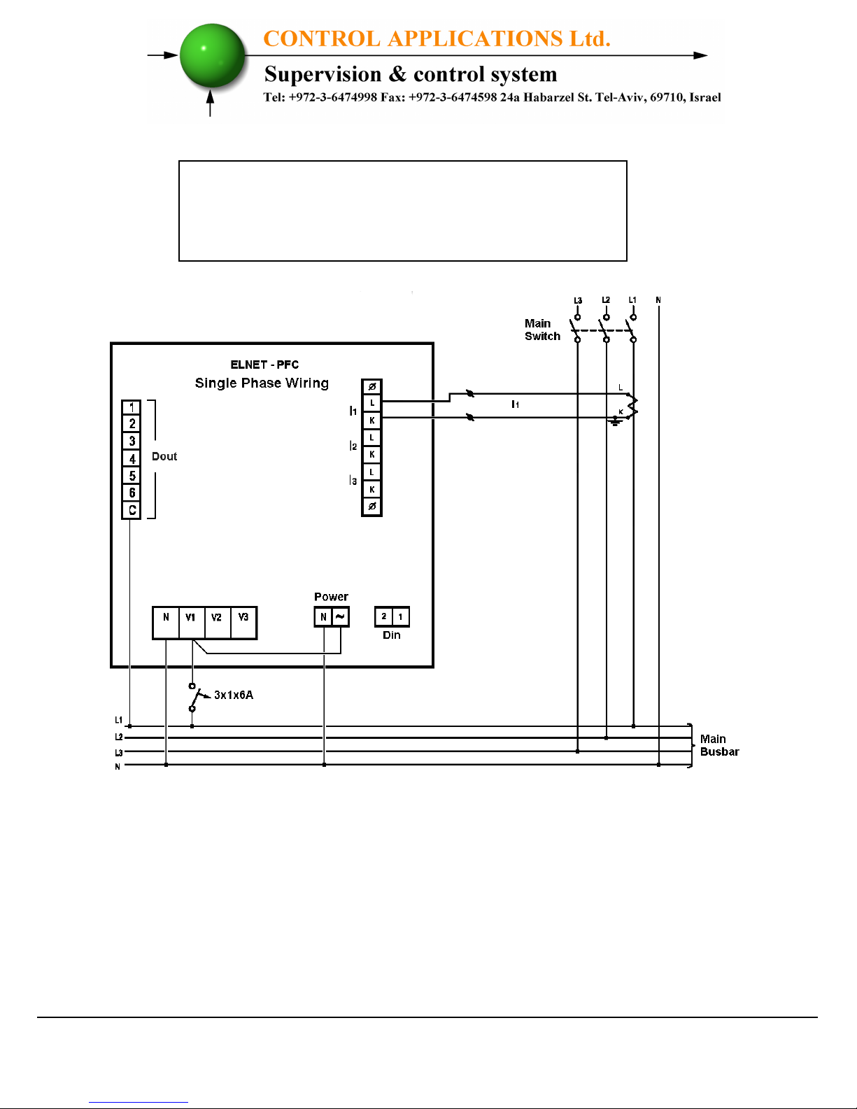
Notice!
The distance between the external current
transformer and the Elnet will not exceed 5m
Attention! Maximum current for contactors R1 up to R6 is up to 3A
Page 6
- 6 -
Notice!
The distance between the external current
transformer and the Elnet will not exceed 5m
Figure 1.2 – Single Phase Electrical wiring diagram
Page 7
- 7 -
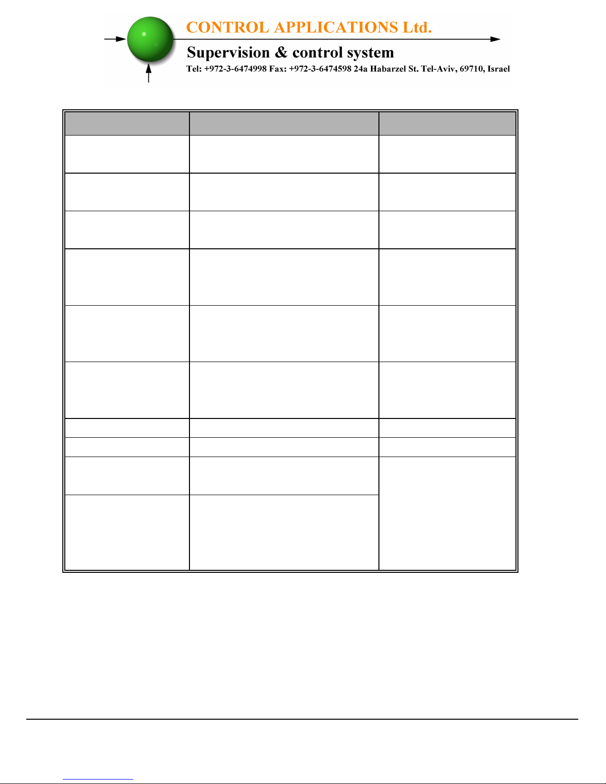
Figure 1.3 – Connections on the back of the device
Pin Designation
Description Remarks
V1 Line 1 - Voltage Supply
Use 6Amp fuse to
protect the line
V2 Line 2 - Voltage Supply
Use 6Amp fuse to
protect the line
V3 Line 3 - Voltage Supply
Use 6Amp fuse to
protect the line
I1
From external Current
Transformer on Line1
Note the correct
direction to insert
the lead
I2
From external Current
Transformer on Line2
Note the correct
direction to insert
the lead
I3
From external Current
Transformer on Line3
Note the correct
direction to insert
the lead
~~~~
Power 110 - 280 VAC OR 90-250 VDC
N
Neutral Neutral Line
Digital Out
1 2 3 4 5 6
Relay outputs for switching
the capacitor's contactors.
Recommended
operational load up
to 5 Amp
C
Common connector for
feeding voltage\neutral to
all the contact relay
outputs.
Page 8
- 8 -
1.3. Test Relays Screen
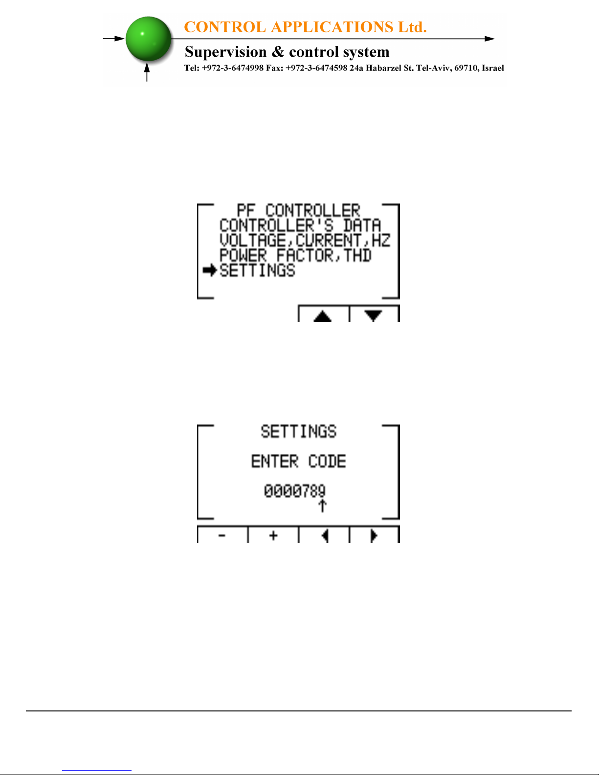
1. From the Main Menu scroll to Settings and press "Enter".
Figure 1.4 – Access the Settings screen
2. The ENTER CODE screen appears.
Figure 1.5 – Enter Code screen
3. The password to activate the Test Relay screen is 789.
4. Use the buttons F3 & F4 to move the cursor, to set the value
use buttons F1 & F2, when finished click “ENTER”.
Page 9
- 9 -
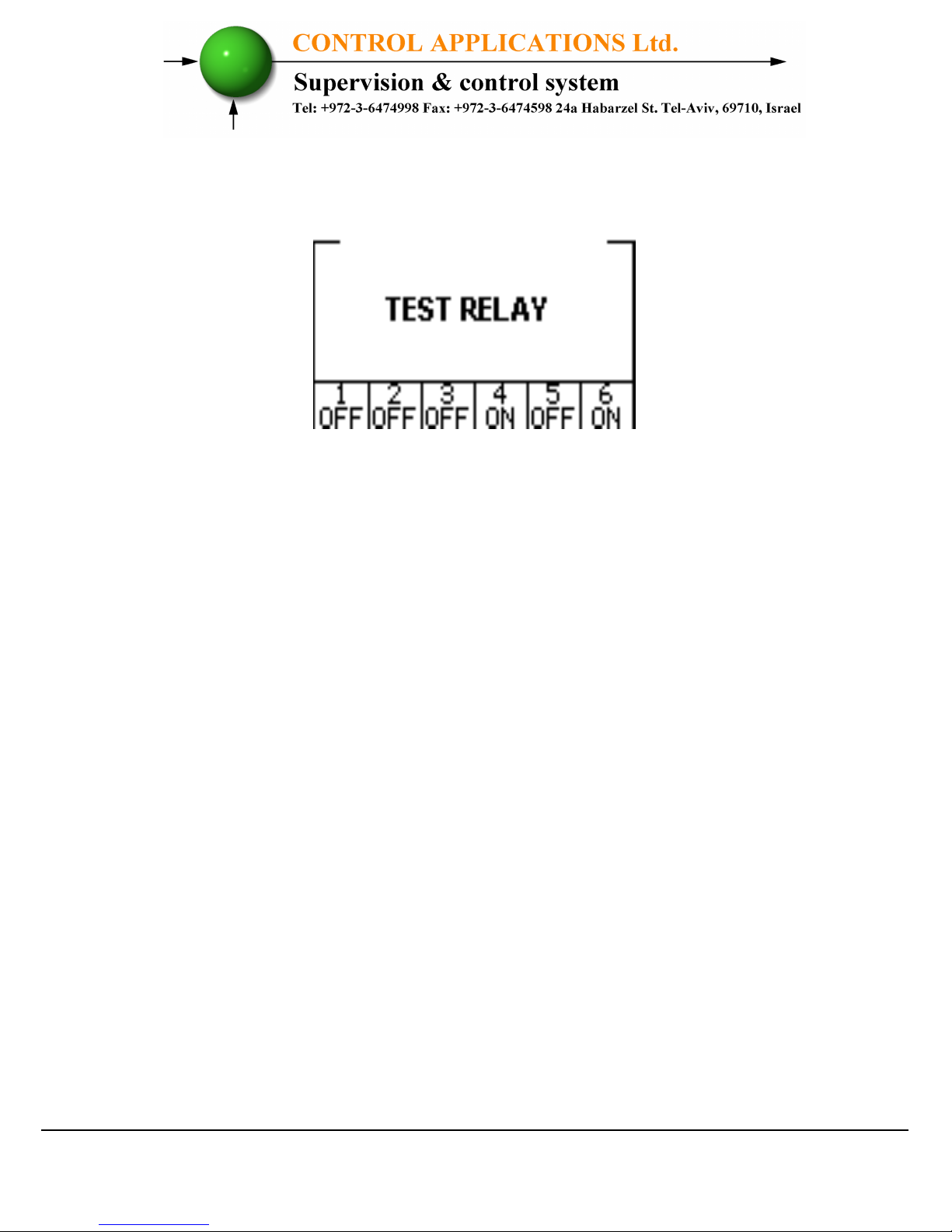
5. The TEST RELAY screen will appear.
Figure 1.6 – Test Relay screen
6. Use the navigation buttons to force and release the relevant
output.
7. When finished hold the "Back" pushbutton until the main
menu appears.
Page 10
- 10 -
CHAPTER 2 – Power Factor Controller
2.1 General Information.
ElNet PFC Power Factor Controller enables measurement and
display of voltage, current, frequency, power factor, THD current
and THD voltage.
Based on the above mentioned measurements ElNet PFC
corrects the power factor by switching the capacitors.
Elnet PFC enables automatic identification of capacitors' size
and its connection in various methods.
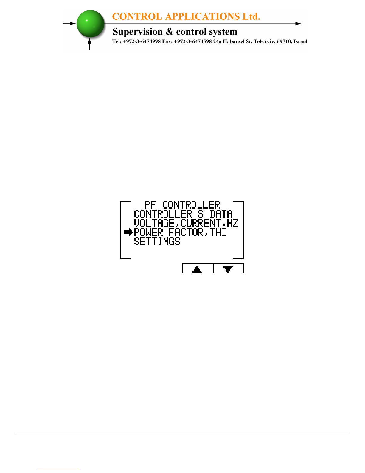
ElNet PFC Main Menu includes the following functions:
Figure 2.1 – Main Menu
Controller's data screen - enables displaying the readings of power
factor and the capacitor status.
Voltage, Current, Hz screen - enables displaying the readings of
voltage, current and frequency measurements.
Power Factor, THD screen - enables displaying the readings of
power factor, THD voltage and current per phase.
Settings screen - enables setting all values requested for proper
operation of the power factor controller.
Page 11
- 11 -
2.2 Controller's Data Screen.
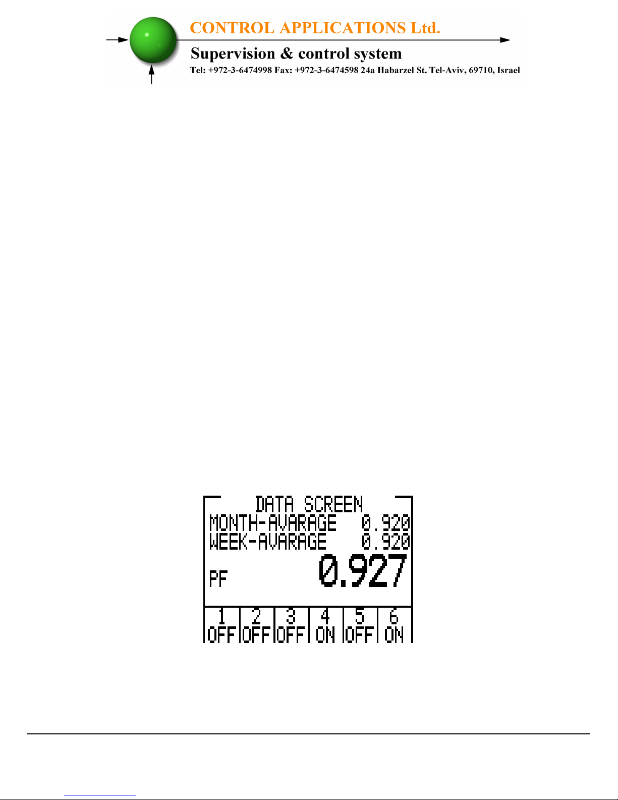
Selection of "CONTROLLER'S DATA" from the main menu
displays monthly and weekly average power factor (from the last
power startup) and also real time power factor. In addition, at the
bottom line you can see which capacitors are connected and which
ones are disconnected. In case of fault one of the following
messages appears:
• "Low Current" – Appears in case of measured current is lower
than in the allowed "Working range" definitions.
• "High THD" - Appears in cases of measured current\voltage
THD is higher than in the allowed "Working range" definitions.
• "Volt Range Error" - Appears in cases of measured voltage is
lower\higher than in the allowed "Working range" definitions.
• "Capacity Load" - Appears in cases of the system is turned to
capacitive.
• "Need More Capacitors" – Appears in cases of all the capacitors
are ON, however the desirable Set Point is unreachable.
Figure 2.2 – Data Screen
Page 12
- 12 -
2.3 Voltage, Current, Hz.
Selection of "Voltage, Current, Hz" menu from the main menu
will grand access to all the basic measuring of the device.
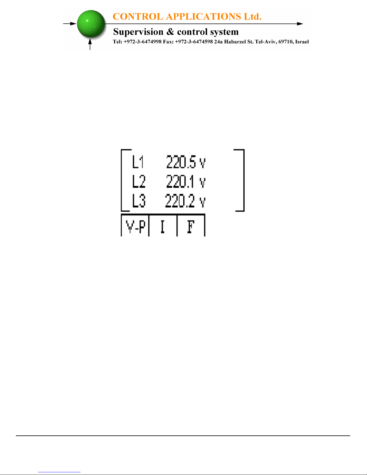
1. From the Main Menu scroll to the
Voltage, Current, Hz
menu and press "Enter", the Voltage screen appears.
Figure 2.3 – Voltage, Current, Hz.
2. Use the F1, F2, F3 pushbuttons to choose the monitored on
screen data (Voltage, Current, Frequency).
2.4 Power Factor, THD.
Selection of
"Power Factor, THD"
menu from the main menu
will grand access to the readings of Power Factor per line, and to
the THD of voltage and current per line.
Page 13
- 13 -
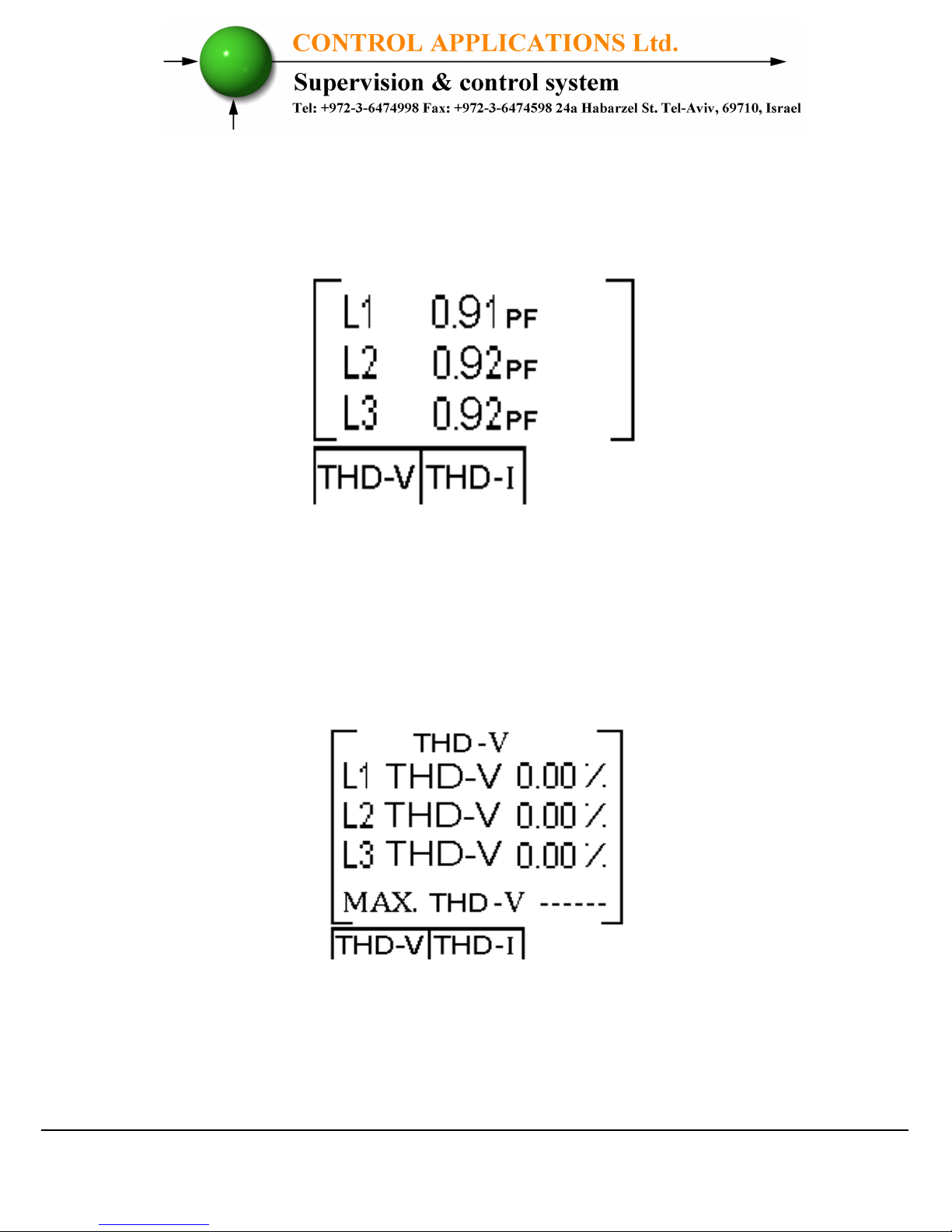
1. From the Main Menu scroll to the
Power Factor, THD
menu, and press "Enter", the Power Factor screen appears.
Figure 2.4 – Power Factor screen.
2. Pressing on "F1" (THD-V),"F2" (THD-I) buttons allow to
access the THD data screens.
Figure 2.5 – THD screen.
Page 14
- 14 -
CHAPTER 3 – Power Factor Controller Settings
In order to set all values requested for proper operation of the
Power factor controller, the following settings must be
defined: Transformer Ratio, Vital Setting, Non Vital
Setting & Working Range.
3.1 Single \ Three Phase modes.
1. Setting the PFC to operate in single phase or three phase
mode will effect only on the screen appearance the rest of the
features and settings will remain to be the same as described
in the other chapters of this manual.
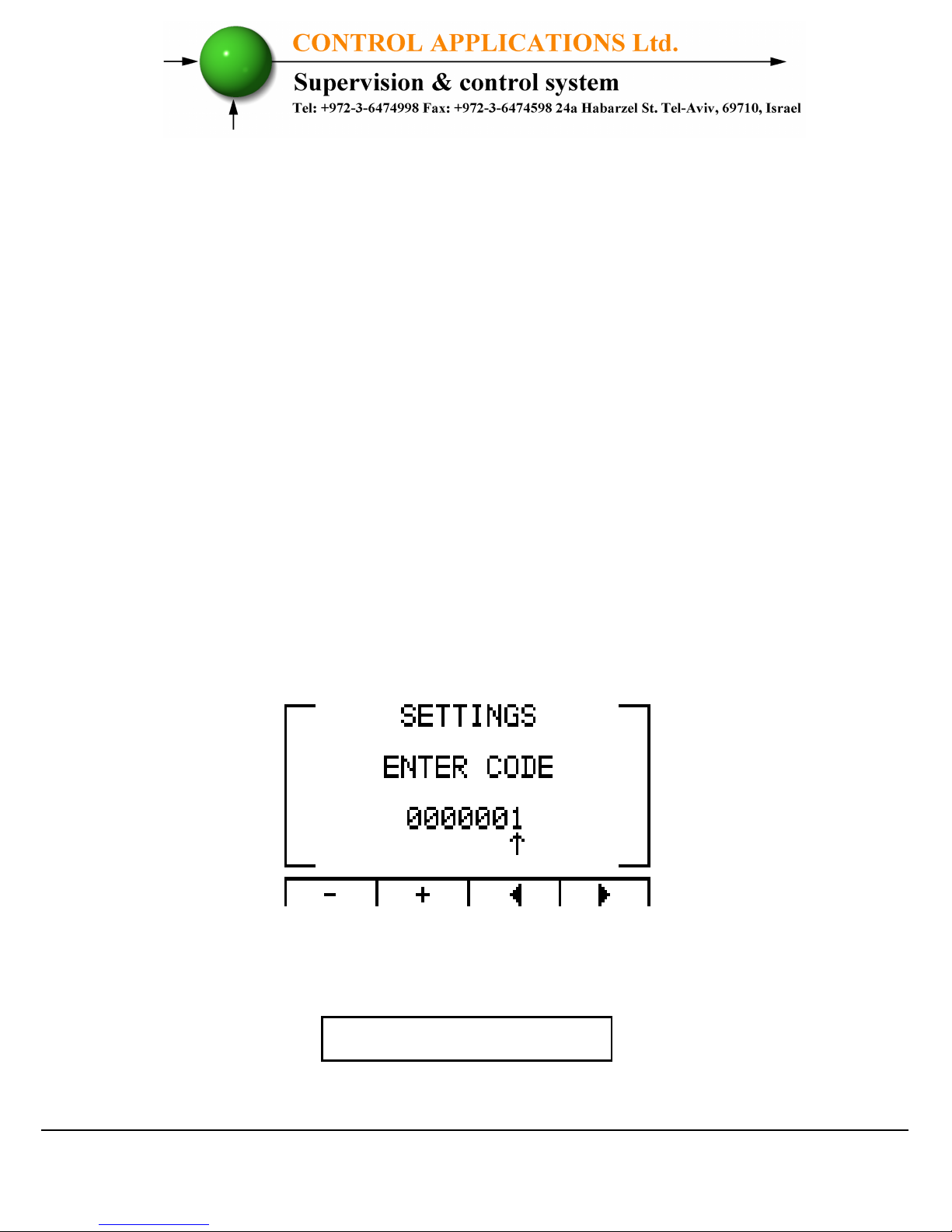
2. From Main Menu scroll to SETTING and press "Enter", The
Enter Code screen appears.
Figure 3.1 - Enter Password
The password is 1.
Page 15
- 15 -
3. Use the buttons F3 & F4 to move the cursor, to set the value
use buttons F1 & F2, when finished click “ENTER”.
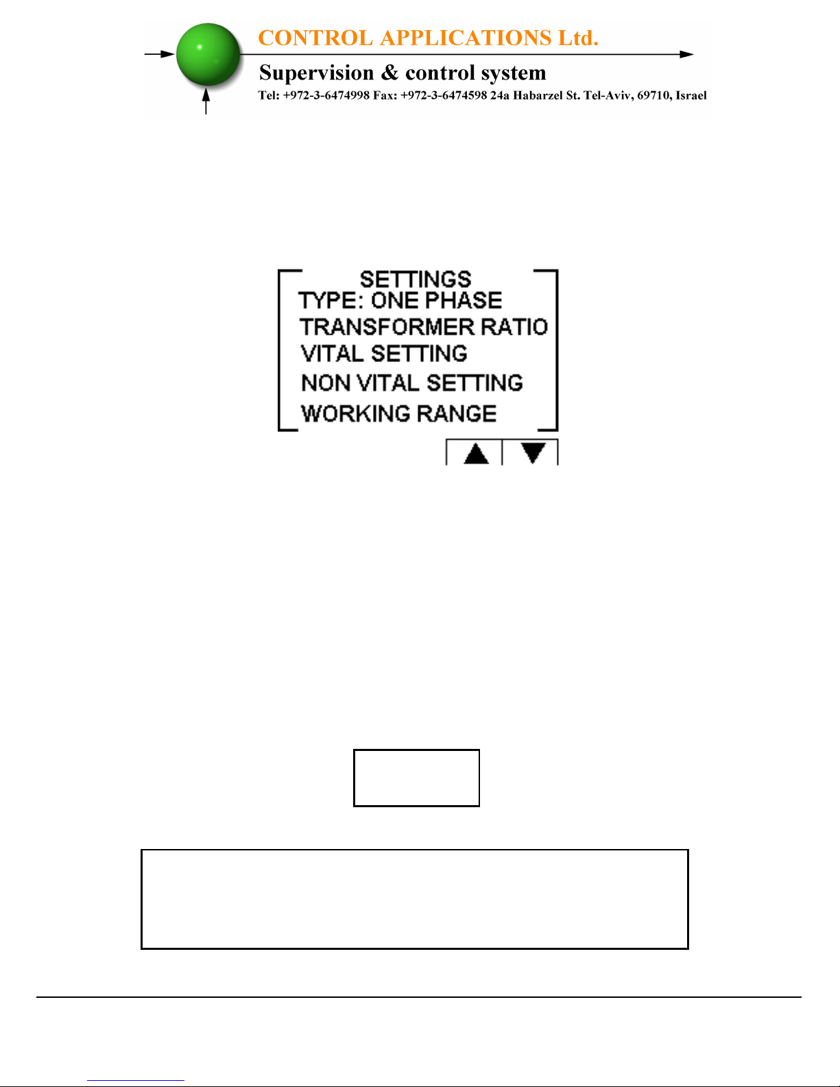
4. The Setting screen appears.
Figure 3.2 – Settings.
5. Scroll to TYPE and click Enter in order to change the mode
between single phase and three phases.
3.2 Transformers Ratio.
1. From Main Menu scroll to SETTING and press "Enter", The
Enter Code screen appears.
If the incorrect password is inserted into the Password
field, an Error message appears and the password
should be reentered
NOTE!
Page 16
- 16 -
2. The Setting screen appears. (Please see figure 3.2).
3. Scroll to "Transformer Ratio" and press "Enter". The
Transformer Ratio screen appears.
4. In order to set the Current Transformers ratio, scroll to
Current Trans and press "Enter".
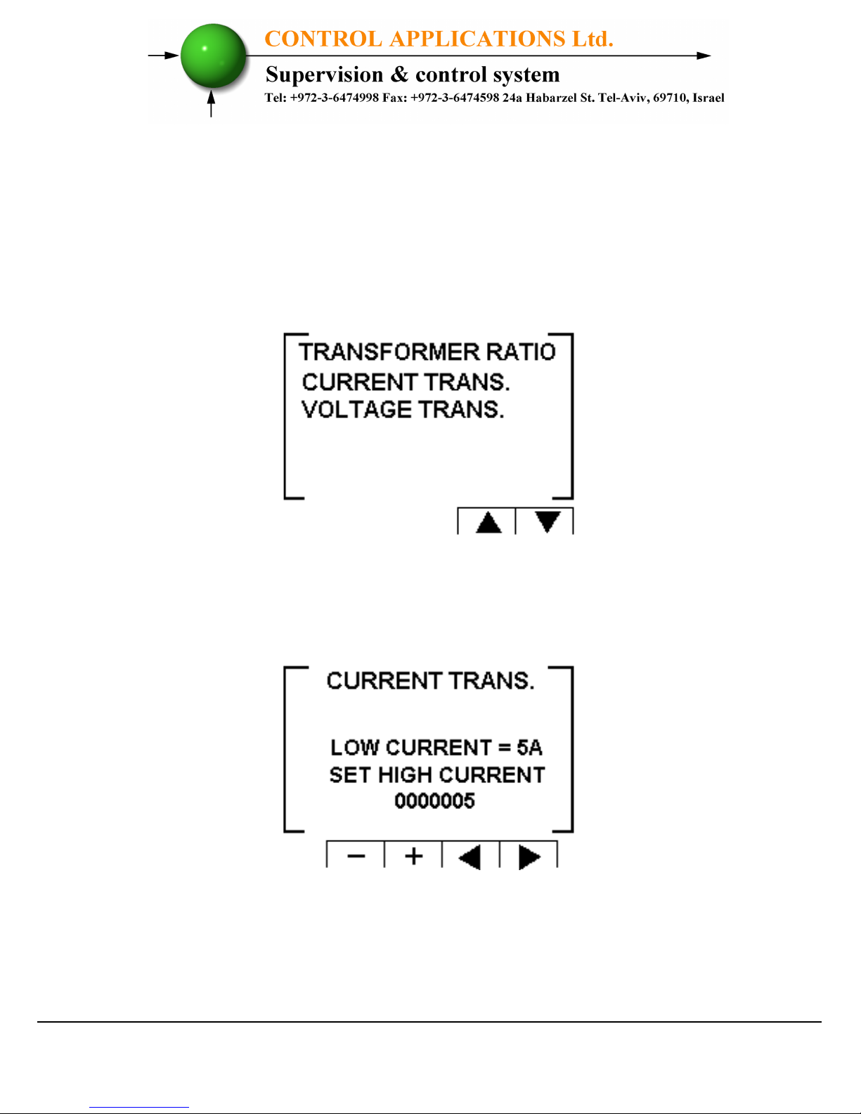
Figure 3.3 – Transformer Ratio.
5. The Current Transformer screen appears.
Figure 3.4 – Changing Transformer Ratio.
Page 17
- 17 -
6. Use the buttons F3 & F4 to move the cursor, to set the value
use buttons F1 & F2, when finished click “ENTER”.
7. In order to set the Voltage Transformers ratio, scroll to
Voltage Trans and press "Enter".
8. Use the buttons F3 & F4 to move the cursor, to set the value
use buttons F1 &F2, when finished click “ENTER”.
3.3 Vital Setting.
In order to define the Vital Setting, you must access the Setting
screen by repeating steps from chapter 3.1, paragraphs 1,2,3.
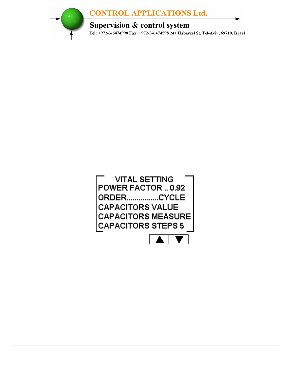
1. Once the Setting screen appears, scroll to Vital Setting and
press "Enter". The Vital Setting screen appears.
Figure 3.5 – Vital Setting screen.
Page 18
- 18 -
3.3.1 Setting the Power Factor Set Point:
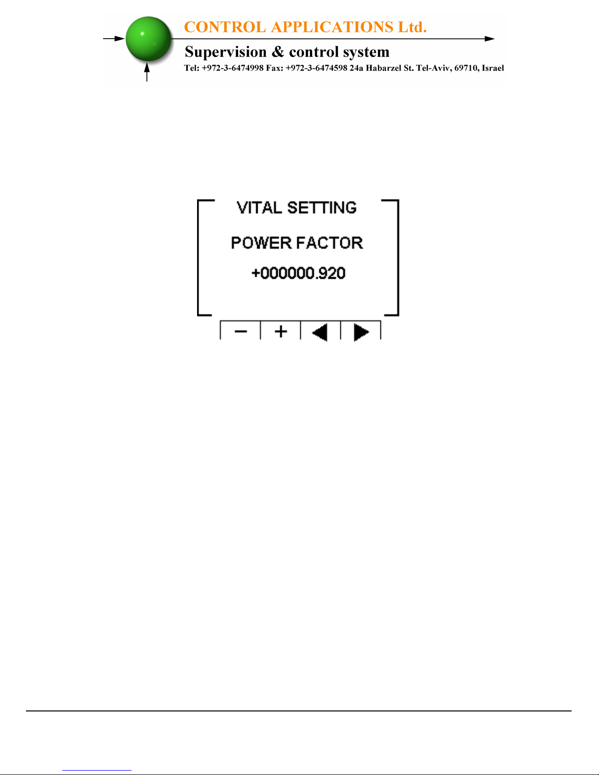
1. Scroll down to Power Factor and press "Enter".
2. The Power Factor setting screen appears.
Figure 3.6 – Power Factor change.
3. Use the buttons F3 & F4 to move the cursor, to set the value
use buttons F1 &F2, when finished click “ENTER”.
3.3.2 Changing the Capacitors Connection Order
:
1. At the Vital Setting screen scroll down to "ORDER".
2. Each time you press Enter at the line indicating "ORDER",
the connection order options will be changed from the
following possibilities: "RANDOM", "FIRST", "CYCLE".
3. The capacitors chosen for power factor correction are chosen
according to their size, meaning that it chose the minimal
number of the capacitors for achieving the requested value of
the power factor.
Page 19
- 19 -
4. There are a number of methods as following:
"RANDOM" - this method enables random selection of equallysized capacitors. In this method after a certain period, the number
of the working hours, of all equally-sized capacitors will be equal.
"FIRST" - this method enables fixed selection, meaning a certain
capacitor will always be first and the other will always be second
and third and so on – this method is recommended in places
preferring unequal working hours of the capacitors.
"CYCLE" - whenever there are a few capacitors of equal size
there is a possibility to use the "cycle" method so that the number
of working hours will be equally divided between these capacitors.
3.3.3 Capacitor's Value setting:
1. In order to define manually the values of the capacitors which
are used in the system, at the Vital Setting screen scroll down
to Capacitors Value, and press "Enter".
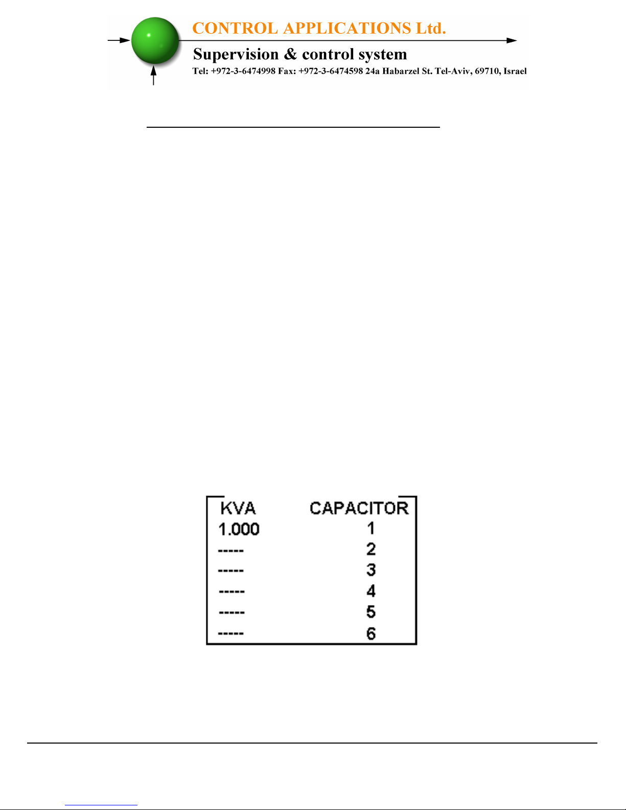
2. The Capacitor Value screen appears.
Figure 3.7 – Capacitor Value screen.
Page 20
- 20 -
3. In order to manually define the value of the capacitor step,
use F3 & F4 buttons to scroll between steps, and press
"Enter" in order to access the value setup.
4. The Capacitors Value screen appears, Use the buttons F3 &
F4 to move the cursor, to set the value use the buttons F1 &
F2, when finished click “ENTER”.
3.3.4 Capacitor's Value measure:
1. The Elnet PFC enables true capacitors value measure for
capacitors 1 up to 6.
2. In order to measure and automatically define the values of the
capacitors which are used in the system, at the Vital Setting
screen scroll down to Capacitors Measure, and press "Enter".
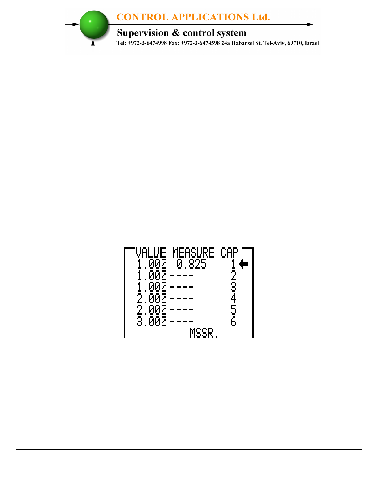
3. The Value Measure screen appears.
Figure 3.8 – Value measure of the capacitors.
4. Once the Value Measure screen appeared, the PFC will
automatically begin measuring process. It will scan and
measure each capacitor step, one by one, the whole process
may take a few minutes.
Page 21

- 21 -
5. Once the measuring process is finished, the measured values
appear on screen.
6. The column "MEASURE" indicates the measured values.
7. The column "VALUE" indicates the capacitor's value as
defined by the user.
8. The "RND" button enables correction of the measured values
to the closest rounded value under the condition that the
difference between the capacitors doesn't exceed 10%.
9. The "SAVE" button enables saving the measured (and/or
rounded) values instead of the values entered by the user at
the previous screen "capacitors value".
3.3.5 Capacitor's steps
:
1. In order to set the number of the capacitors steps in the
system, at the Vital Setting screen scroll down to Capacitors
Steps, and press "Enter".
2. The Capacitors Steps screen appears. Use the buttons F3 &
F4 to move the cursor, to set the value use buttons F1 & F2,
when finished click “ENTER”.
3.4 Non-vital setting
In order to define the Non-Vital Setting, you must access the
Setting screen by repeating steps from chapter 3.1, paragraphs
1,2,3.
1. Once the Setting screen appears, scroll to Non Vital Setting
and press "Enter".
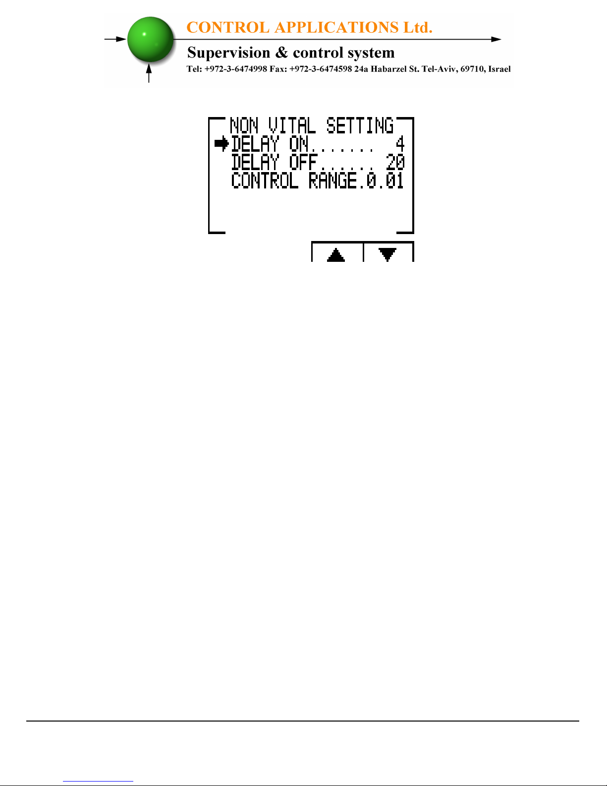
2. The Non Vital Setting screen appears.
Page 22
- 22 -
Figure 3.9 – Non vital setting.
3.4.1 "DELAY ON":
1. Delay On enables setting the delay (seconds) between the
decision of connecting the capacitor and its actual connection.
This delay is meant to minimize the number of
connections/disconnections of the capacitors during control
of the desired power factor value.
2. In order to change the delay on, scroll to DELAY ON and
press "Enter". The Delay On screen appears.
3. Use the buttons F3 & F4 to move the cursor, to set the value
use buttons F1 & F2, when finished click “ENTER”.
3.4.2 "DELAY OFF":
1. Delay Off enables setting the delay (seconds) between the
decision of disconnecting the capacitor and its actual
disconnection. This delay is meant to minimize the number of
connections/disconnections of the capacitors during control
of the desired power factor value.
2. In order to change delay off, scroll to DELAY OFF and press
"Enter". The Delay OFF screen appears.
Page 23

- 23 -
3. Use the buttons F3 & F4 to move the cursor, to set the value
use buttons F1 & F2, when finished click “ENTER”.
3.4.3 "CONTROL RANGE":
1. Control Range enables the user to define the working range of
the capacitors in performing power factor correction. When
the "control range" = 0.01 the system is looking for the
minimal capacitors number for performing power factor
correction from the desired value (for example, 0.92) to the
value 0.93 = 0.92+0.01 (control range). From this point, the
system is looking for the minimal capacitors' combination
required, for reaching the power factor of 0.93 and its
disconnecting capacitors accordingly.
2. In order to change Control Range scroll to Control Range line
and press "Enter". The Delay Control Range screen appears.
3. Use the buttons F3 & F4 to move the cursor, to set the value
use buttons F1 & F2, when finished click “ENTER”.
3.5 Working range settings
Working range settings enable defining limits for current,
voltage, THD V and THD I values.
In order to define the Working Range Setting, you must access
the Setting screen by repeating steps from chapter 3.1, paragraphs
1,2,3.
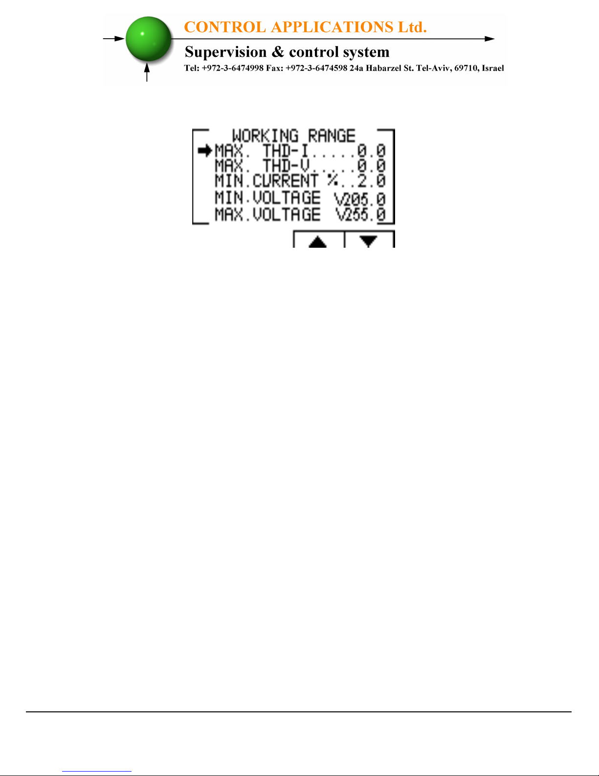
1. Once the Setting screen appears, scroll to Working Range and
press "Enter". The Working Range screen appears.
Page 24
- 24 -
Figure 3.10 – Working range settings.
3.5.1 "MAX. THD I" setting:
1. Enables disconnection of all the capacitors whenever the
actual THD I value exceeds the value which was defined by
the user. When THD I = 0 this option is disabled.
2. In order to change the Max. THD-I, scroll to Max. THD-I line
and press "Enter". The Max. THD-I screen appears.
3. Use the buttons F3 & F4 to move the cursor, to set the value
use buttons F1 & F2, when finished click “ENTER”.
3.5.2 "MAX. THD V" setting:
1. Enables disconnection of all the capacitors whenever the
actual THD V value exceeds the value which was defined by
the user. When THD V = 0 this option is disabled.
2. In order to change the Max. THD-V, scroll to Max. THD-V
line and press "Enter". The Max. THD-V screen appears.
3. Use the buttons F3 & F4 to move the cursor, to set the value
use buttons F1 &F2, when finished click “ENTER”.
Page 25

- 25 -
3.5.3 "MIN. CURRENT %" setting:
1. Enables defining value for minimal current under which
power factor correction is not required, the value entered as
% of the maximum current at the secondary current
transformer.
2. In order to change the Min. Current %, scroll to Min. Current
% line and press "Enter". Min. Current % screen appears.
3. Use the buttons F3 & F4 to move the cursor, to set the value
use buttons F1 & F2, when finished click “ENTER”.
3.5.4 "MIN. VOLTAGE" setting:
1. Enables defining voltage low limit value, under this value all
the capacitors will be disconnected.
2. In order to change the Min. Voltage, scroll to Min. Voltage
line and press "Enter". The Min Voltage screen appears.
3. Use the buttons F3 & F4 to move the cursor, to set the value
use buttons F1 & F2, when finished click “ENTER”.
3.5.5 "MAX. VOLTAGE" setting:
1. Enables defining voltage high limit value, above this value all
the capacitors will be disconnected.
2. In order to change the Max. Voltage, scroll to Max. Voltage
line and press "Enter". The Max Voltage screen appears.
3. Use the buttons F3 & F4 to move the cursor, to set the value
use buttons F1 & F2, when finished click “ENTER”.
 Loading...