

Page 1
Doorbell and Phone Event
Package
Installation Guide
Package contents
Doorbell and Phone Event Package (ZCA-IDP10A)
• 2 Wireless Contact Sensors
• 1 North American External Power Supply (for optional DC
powering of the Wireless Contact Sensor)
• 1 ELK-930 Doorbell and Telephone Ring Detector
Note: The package has been tested and designed to
work with Control4 OS1.3.2 and later. All necessary
drivers for the package are included in these Control4
versions.
Introduction
The Doorbell and Phone Event Package is an all-in-one solution
that makes it quick and easy to add doorbell- and phone-based
automation events in a Control4 home. With everything you need
in a single box, the package includes all the gear to create events
for one or two doorbells and one phone line.
The Wireless Contact Sensor operates on either two AA batteries
or a low-voltage power supply (included). This single, small
device combines up to three contact switches, two temperature
sensors, and—when line-powered—a ZigBee repeater.
The ELK-930 Doorbell and Telephone Ring Detector detects
ring activation from one or two doorbell buttons and a single
telephone line. It conveniently isolates the voltage and current
and produces an open collector (pull to ground) output which
can be used to trigger the Wireless Contact Sensor. The
ELK-930’s circuit board is pre-scored so that the three individual
detectors may
be snapped o (separated) from each other.
Installing the doorbell event detector
Also see “Creating doorbell ring detection-based events” on page
3.
To install the doorbell event detector:
1 Add one Wireless Contact Sensor to the Composer project
and create the proper bindings. (Refer to the Wireless
Contact Sensor Installation Guide.)
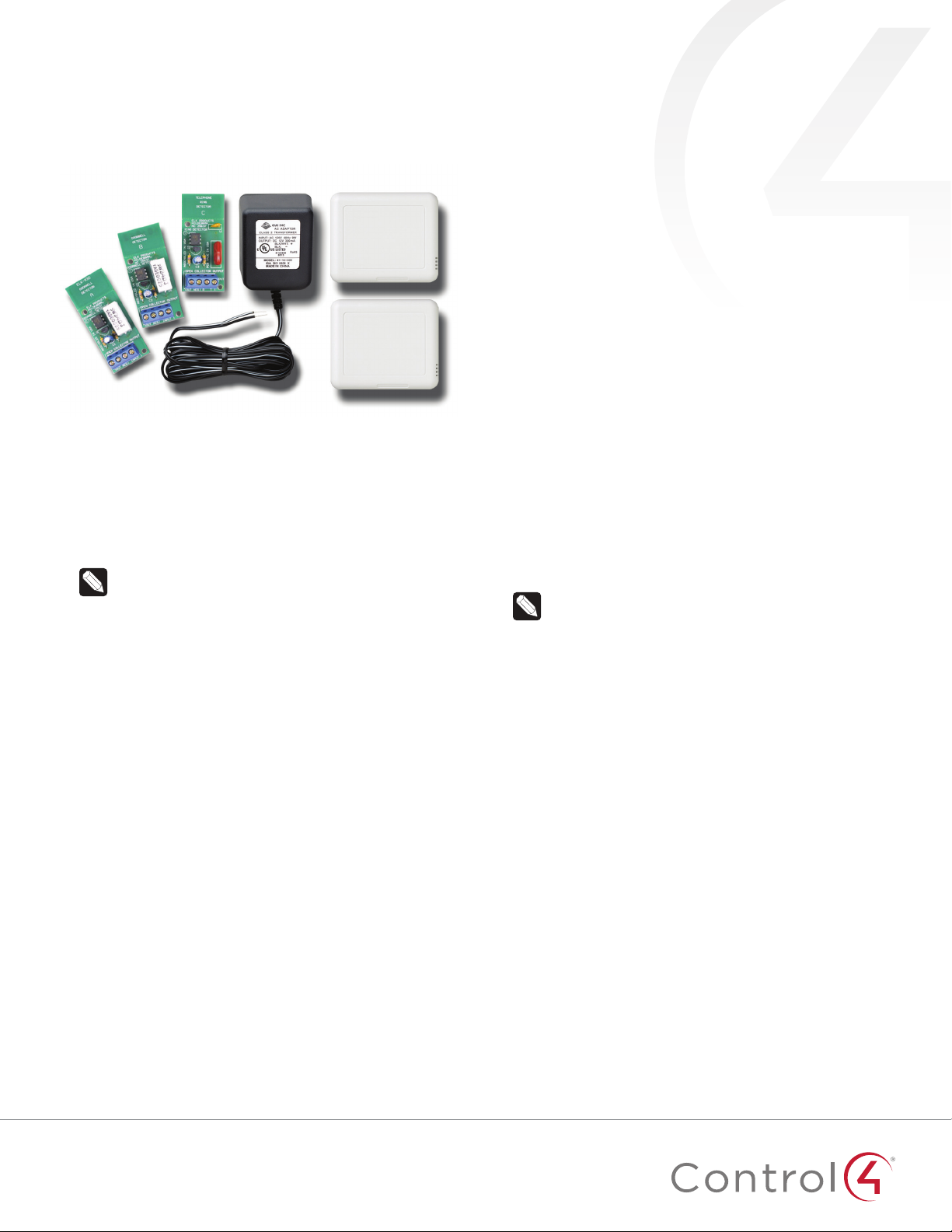
2 Using two jumper wires similar in gauge to the existing
doorbell ringer circuit, connect the doorbell circuit’s
transformer and front door input to the two INPUT terminals
on the ELK-930 Doorbell Ring Detector.
3 Using two jumper wires similar in gauge to the existing
doorbell ringer circuit, connect pins 1 and 2 on the Wireless
Contact Sensor to the OUT and NEG terminals on the
ELK-930.
4 Using the included adhesive foam, mount the ELK-930 to a
location near the doorbell ringer/transformer assembly.
Note: No enclosure is provided or required for the
ELK-930. You should exercise caution and not place it
in such as way as to short the ELK-930’s printed circuit
board (PCB).
5 Using the included mounting screws and wall anchors,
mount the Wireless Contact Sensor to a location near the
doorbell ringer/transformer assembly.
6 Using Composer Pro, you can now add events around the
ringing of the doorbell, such as:
• Mute all audio zones for five to 10 seconds to allow
occupants to hear the doorbell ringing.
• Flash the lights in rooms where it’s dicult to hear the
doorbell ringing.
• Activate an IP camera (not included) located at the door
and use a camera preset to see who’s there.
11
Page 2
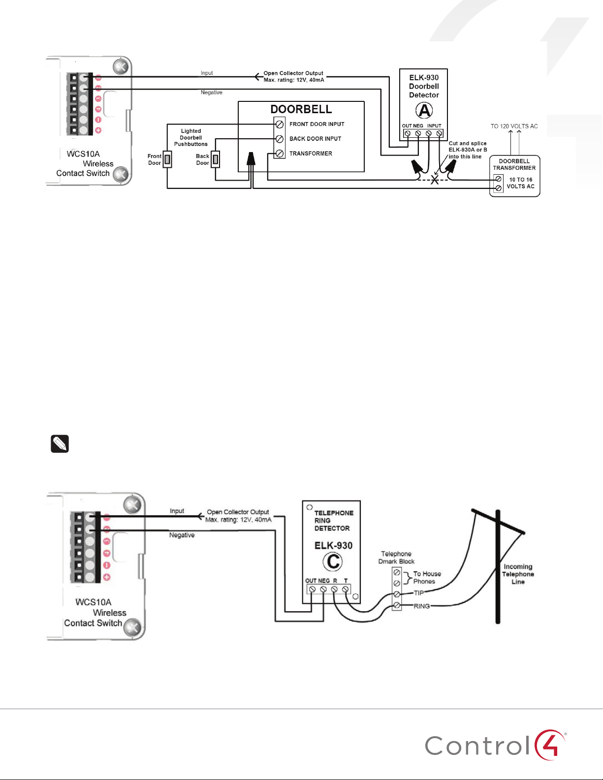
Figure 1: Doorbell Ring Detector wiring diagram
Installing the telephone ring event detector
Also see “7 In the Actions pane, select Programming Control.
Then, in the Programming Control Actions pane, enter a delay
time (for example, 500-1,500 milliseconds).” on page 6
To install the telephone ring event detector:
1 Add one Wireless Contact Sensor to the Composer project
and create the proper bindings. (Refer to the Wireless
Contact Sensor Installation Guide.)
2 Using two jumper wires similar in gauge to the existing
telephone circuit, connect the telephone TIP and RING
wires for one line to the T and R terminals on the ELK-930
Telephone Ring Detector.
3 Using two jumper wires similar in gauge to the existing
telephone circuit, connect pins 1 and 2 on the Wireless
Contact Sensor to the OUT and NEG terminals ELK-930.
4 Using the included adhesive foam, mount the ELK-930 to a
location near the telephone line.
Note: No enclosure is provided or required for the
ELK-930. You should exercise caution and not place it
in such as way as to short the ELK-930’s printed circuit
board (PCB).
5 Using the included mounting screws and wall anchors,
mount the Wireless Contact Sensor to a location near the
telephone line.
6 Using Composer Pro, you can now add events around the
ringing of the telephone, such as:
• Mute all audio zones for five to 10 seconds to allow
occupants to hear the telephone ringing.
• Flash the lights in rooms where it’s dicult to hear the
telephone ringing.
Figure 2: Telephone Ring Detector wiring diagram
2
Page 3

Creating doorbell ring detection-based
events
Knowing someone’s at the door doesn’t seem like a big deal.
However, with doorbell chimes in random locations, usually away
from central living areas, all it takes is some loud music or a
family member with poor hearing to miss someone at the door.
Using the Doorbell and Phone Event Package, you can create
a home automation event that alerts the homeowner when the
doorbell is pressed.
For example, the event can cause a room’s lights to flash, mute an
audio zone’s speaker volume, or trigger an IP camera by the door.
These instructions provide you with ideas for added capabilities
you can provide to your customers and walk you through the
setup process to implement these ideas.
The Doorbell and Phone Event Package easily integrates with
Control4 and a homeowner’s installed doorbell. It includes the
ELK-930 that detects ring activation, isolates the voltage and
current, and produces an open collector (pull-to-ground) output
used to trigger a contact close event in the package’s Wireless
Contact Sensor.
Installing the hardware
Programming in Composer Pro
Step one: Add the Wireless Contact Sensor driver to the
Composer project.
1 Open Composer Pro and the project, then select the System
Design view.
2 Under Search, enter Control4 Wireless Contact Sensor.
Figure 3: Wireless Contact Sensor driver search
3 Select the contact sensor to add it to the project.
Step one: Connect the ELK-930 Doorbell Detector and Wireless
Contact Sensor to the doorbell circuit.
1 Using the INPUT terminals, wire the ELK-930 Doorbell
Detector Module into the circuit path between the doorbell
transformer and the doorbell.
2 Run one wire of similar gauge to the doorbell wire from
the OUT terminal on the Doorbell Detector Module to the
SWITCH 1 terminal on the Wireless Contact Sensor’s Tray
Assembly.
3 Run another wire of similar gauge from the NEG terminal on
the Doorbell Detector Module to the COMMON 1 terminal on
the Wireless Contact Sensor’s Tray Assembly.
Step two: Place the Doorbell Detector Board and Wireless
Contact Sensor.
1 After connecting the Wireless Contact Sensor to the
ELK-930 Doorbell Detector Module, you can place it above
the doorbell chime façade that covers the plunger/solenoid
using the contact switch’s enclosed molly anchors.
2 After making all the wire connections between the circuit
path, the Wireless Contact Sensor, and the ELK-930
Doorbell Detector Module, you can secure the module to an
appropriate surface using the two included adhesive pads.
Note: Often the façade covering the plunger/solenoid
activating the doorbell chimes is large enough to
conceal the Doorbell Detector Module.
Step two: Add lighting events to rooms.
1 In System Design View, add (if needed) the desired light
switch to the event room.
2 Add a generic doorbell sensor driver to the room where the
event will take place.
3 In Connections View, bind the Doorbell driver’s Contact
Sensor input to the appropriate contact output of WCS10A.
Figure 4: Binding doorbell to Wireless Contact Sensor input
4 Go to the Programming View, and from the Device Events
window in the upper left, select Doorbell.
3
Page 4

5 In the Doorbell Events window immediately below, select
When the Doorbell is pressed.
Figure 5: Setting the doorbell event
6 In the Actions pane in the upper-right, select the lighting
device.
7 In the Light Commands pane, select Toggle, and drag the
green arrow icon into the Script pane two times.
8 In the Actions pane, select Programming Control, then in the
Programming Control Actions pane, enter a delay time (for
example, 500-1,500 milliseconds).
Step three: Add audio events to rooms.
Note: Composer does not include an Announcement
agent to support interrupting and resuming music
sessions, so a workaround has been devised to enable
this capability. To create audio events that interrupt and
resume an existing music session in a room, you need
to make use of unused audio out ports on other devices
in the project. An unused audio out port is any physical
audio out port not currently connected to some other
device in the project. Some commonly unused audio out
ports in projects are the RCA jacks in Speaker Points
and any unused audio out ports on home controllers.
1 In Composer Pro, go to the System Design View and add a
new room called “Phantom Room” for every room where
you plan for the event to take place. (This room name
will be used throughout these instructions. During actual
installation, you should create your preferred room name
such as Phantom Family Room and Phantom Garage.)
2 In the Connections View, select the “Phantom Room” and
bind its audio end point to an unused audio out port.
3 Then, again using the Connections View, bind ContactInput1
to the Doorbell.
Figure 6: Adding delay
9 Drag the green arrow icon and drop it between the two
Toggle actions.
Figure 7: Programming
Note: You can repeat the delay-and-toggle steps
multiple times as desired. If the instructions above are
used “as is,” the light will flash only once. The delay
time can be varied depending on the installer and the
homeowner’s preference. If the homeowner doesn’t like
the abrupt flashes, the script can be modified to use a
series of ramp-to-level actions instead.
Figure 8: Binding audio endpoint to audio out
4 Go to the Programming View, and from the Device Events
window in the upper left, select Doorbell, and in the Doorbell
Events pane immediately below, select When the doorbell is
Pressed.
5 In the Actions pane in the upper right, select Digital Media.
Figure 9: Select Digital Media
4
Page 5

Step four: Select rooms and media for a doorbell event.
1 On the Selected Room menu, select the room in where you
want the event to take place.
2 Click Add Rooms, select the Phantom Room box, and add
this command to your script.
Figure 10: Adding the Phantom Room to the command
3 Go back to the Selected Room menu and select Phantom
Room.
4 Click Remove Rooms, select the box with the name of the
room where the event will take place, and add this command
to your script.
5 In the Actions pane, select the room where the event will
take place, click Select Media, and choose an MP3 file to play
as your event.
Step five: Customize the doorbell event.
1 In the Actions pane, select Programming Control.
2 Click Delay, set it to about 10 seconds (this can be increased
or decreased depending on the desired length of the
doorbell event), and add this command to your script.
3 In the Actions pane, select Digital Media.
4 In the Selected Room menu, select Phantom Room, click
Add Rooms, select the box with the name of the room where
the event will take place, and add this to your script.
5 Return to the Selected Room menu, select the room where
the action will take place, click Remove Rooms, then select
the Phantom Room box.
Figure 11: Finishing the programming
The results
By followng these installation steps, you can provide the
homeowner with either lighting or audio events that let
them know the doorbell is ringing. After the lighting event is
configured, lights in the target room will flash to indicate the
doorbell is ringing.
With the audio event configured, a ringing doorbell pauses
any active audio stream in the target room(s) and plays the
announcement message or music. Following the announcement,
the original audio stream will resume.
Of course, you also have the option of combining these events
into a single lighting and audio event for increased awareness.
This level of customization allows you to create an individual
installation that perfectly suits each homeowner.
Creating telephone ring detection-based
events
Whether you’re trying to make phone ringing more spectacular
(to get children to answer) or more convenient for people away
from the ringing phone, using the Doorbell and Phone Event
Package you can create a home automation event that alerts
the homeowner when the phone rings. For example, the event
can cause a room’s lights to flash, mute an audio zone’s speaker
volume, or trigger an audio event over multiple audio zones.
These instructions provide you with ideas for added capabilities
you can provide to your customers and walk you through the
setup process to implement these ideas.
The Doorbell and Phone Event Package easily integrates with
the Control4 system and a homeowner’s installed analog (non
IP-based) telephone system. It includes the ELK-930, which
detects a telephone ring, isolates the voltage and current, and
produces an open collector (pull-to-ground) output used to
trigger a contact close event in the package’s Wireless Contact
Sensor.
Installing the hardware
Step one: Connect the ELK-930 Telephone Ring Detector
module and Wireless Contact Sensor to the telephone line
circuit.
1 Create a jumper to connect to the telephone line circuit with
one end RJ-11 male-terminated and the other end with the
TIP and RING wires stripped for connection to the Telephone
Ring Detector Module.
2 Connect the jumper’s stripped TIP and RING wires to the T
and R terminals on the ELK-930 Telephone Ring Detector
Module.
3 Connect the RJ-11 terminated end of the jumper into an
available RJ-11 female socket that is already wired into
the telephone line circuit. This inserts the Telephone Ring
Detector Module into the telephone line circuit path.
4 Run one wire of similar gauge to the TIP and RING wires
from the OUT terminal on the Telephone Ring Detector
Module to the SWITCH1 terminal on the Wireless Contact
Sensor’s Tray Assembly.
5 Run another wire of similar gauge from the NEG terminal
on the Telephone Ring Detector Module to the COMMON2
terminal on the Wireless Contact Sensor’s Tray Assembly.
5
Page 6

Step two: Place the Telephone Ring Detector Module and
Wireless Contact Sensor.
1 After connecting the Wireless Contact Sensor to the
ELK930 Telephone Ring Detector Module, you can place the
module out of sight and mount the Wireless Contact Sensor
to a nearby wall or surface using the sensor’s enclosed molly
anchors.
2 After connecting the ELK-930 into the telephone line circuit
path and to the Wireless Contact Sensor, secure the module
to an appropriate and out-of-sight surface using the two
included adhesive pads.
3 Mount the Wireless Contact Sensor to a nearby wall or
surface using the Contact Sensor’s enclosed molly anchors.
Note: Many times the junction box for the telephone line
circuit is large enough to conceal the Telephone Ring
Detector Module.
Programming in Composer Pro
4 In the Programming View, from the Device Events window
in the upper left, select the Telephone Ring Sensor, and in
the Telephone Ring Sensor Events pane immediately below,
select When the Telephone Ring Sensor closes.
5 In the Actions pane in the upper right, select the lighting
device.
6 In the Light Actions pane, select Toggle, and drag the green
arrow icon into the Script pane two times.
7 In the Actions pane, select Programming Control. Then, in
the Programming Control Actions pane, enter a delay time
(for example, 500-1,500 milliseconds).
8 Drag the green arrow icon and drop it between the two
Toggle actions.
Step one: Add the Wireless Contact Sensor driver to the
Composer project.
1 Open Composer Pro and the project, then select the System
Design view.
2 Under Search, enter Control4 Wireless Contact Sensor.
Figure 12: Wireless Contact Sensor driver search
3 Select the contact sensor to add it to the project.
Step two: Add lighting events to rooms.
1 In System Design View, add (if needed) the desired lighting
device to the event room.
2 Add a generic Contact Switch driver to the room where the
event will take place and rename it “Telephone Ring Sensor” .
3 In Connections View, bind the Telephone Ring Sensor driver’s
Contact Sensor input to the appropriate contact output of
the Contact Sensor.
Figure 14: Programming
Note: You can repeat the delay-and-toggle steps
multiple times as desired. If the instructions above are
used “as is,” the light will flash only once. The delay
time can be varied depending on the installer’s and the
homeowner’s preferences. If the homeowner doesn’t like
the abrupt flashes, the script can be modified to use a
series of ramp-to-level actions instead.
Step three: Add audio events to rooms.
Note: Control4 does not include an Announcement
agent to support interrupting and resuming music
sessions, so a workaround has been devised to enable
this capability. To create audio events that interrupt and
resume an existing music session in a room, you need
to make use of unused audio out ports on other devices
in the project. An unused audio out port is any physical
audio out port not currently connected to some other
device in the project. Some commonly unused audio out
ports in projects are the RCA jacks in Speaker Points
and any unused audio out ports on home controllers.
1 In Composer, go to the System Design View and add a new
room called “Phantom Room” for every room where you plan
for the event to take place. (This room name will be used
throughout these instructions. During actual installation, you
should create your preferred room name such as “Phantom
Family Room” or “Phantom Garage.”)
Figure 13: Binding the Telephone Ring Sensor to the Contact Sensor
6
Page 7

2 In the Connections View, select the “Phantom Room” and
bind its audio end point to an unused audio out port.
Figure 15: Binding endpoint to audio out
3 Bind the Contact Input 1 to the Telephone Ring Sensor driver
4 Go to the Programming View, and from the Device Events
window in the upper left, select the Telephone Ring
Sensor, and in the Telephone Ring Sensor Events window
immediately below, select When the Telephone Ring Sensor
opens.
5 In the Actions pane in the upper right, select Digital Media.
5 In the Selected Room menu, select the room where the
action will take place, select Remove Rooms, then select
Phantom Room.
Figure 16: Finishing the programming
The results
By following these steps, you can provide the homeowner with
either lighting or audio events that let them know the telephone
is ringing.
Once the lighting event is configured, lights in the target room
will flash to indicate the telephone is ringing.
With the audio event configured, a ringing telephone pauses
any active audio stream in the target room(s) and plays the
announcement message or music. Following the announcement,
the original audio stream will resume.
Of course, you also have the option of combining these events
into a single lighting and audio event for increased awareness.
This level of customization allows you to create an individual
installation that perfectly suits each homeowner.
Step four: Select rooms and media for a telephone ring event.
1 In the Selected Room menu, select the room where you want
the event to take place.
2 Click Add Rooms, select Phantom Room, and add this
command to your script.
3 In the Selected Room menu again, select Phantom Room.
4 Select Remove Rooms, select the room where the event will
take place, and add this command to your script.
5 In the Actions pane, select the room where the event will
take place, click Select Media, and choose an MP3 file to play
as your event.
Step five: Customize the telephone ring event.
1 In the Actions pane, select Programming Control.
2 Select Delay, set it to about 10 seconds (this can be
increased or decreased depending on the desired length of
the telephone ring event), and add this command to your
script.
3 In the Actions window, select Digital Media.
4 In the Selected Room menu, select Phantom Room, click
Add Rooms, select the room where the event will take place,
and add this to your script.
7
Page 8

Additional resources
The following resources are available for additional support:
• Control4 Knowledgebase and forums
• Control4 Technical Support
• Control4 website:
• Composer documentation available at
For the latest version of this document, open this URL or scan
the QR code on a device that can view PDFs.
www.control4.com
ctrl4.co/docs
MOST RECENT VERSION
.
ctrl4.co/ringevent-ig
Regulatory/Safety information
To review Regulatory information for your particular Control4
products, see the information located on the Control4 website at
ctrl4.co/reg
Patent information
Applicable patents are available at
.
ctrl4.co/patents
.
Warranty
Visit
ctrl4.co/warranty
for details.
Copyright ©2017, Control4 Corporation. All rights reserved. Control4, the Control4 logo, the 4-ball logo, 4Store, 4Sight, Control4 My Home, and Mockupancy are
registered trademarks or trademarks of Control4 Corporation in the United States and/or other countries. All other names and brands may be claimed as the property of
their respective owners. All specifications subject to change without notice.
8
B
DOC-00223-B
2017-03-14 MS
 Loading...