

Page 1

pakedge
WX-1x
WX-1 and WX-1-B
802.11ac Dual Band Access Point
User Guide Version 1.0
device&software
inc
Page 2

Content
System Requirements ......................................................................................................................................................................... 6
Hardware Installation .......................................................................................................................................................................... 6
WX-1/WX-1-B Mounting Options ................................................................................................................................................. 6
Using Provided T-bar ....................................................................................................................................................................... 10
Power Method for the WX-1 ........................................................................................................................................................ 12
Power via PoE Switch ....................................................................................................................................................................... 13
Power using the included power adapter ............................................................................................................................... 13
WX-1x Start Up ................................................................................................................................................................................... 15
Menu Options ..................................................................................................................................................................................... 17
Status ...................................................................................................................................................................................................... 17
Dashboard ............................................................................................................................................................................................ 18
System Log ........................................................................................................................................................................................... 19
Network ................................................................................................................................................................................................. 20
LAN .......................................................................................................................................................................................................... 20
Wireless ................................................................................................................................................................................................. 22
Security Profiles .................................................................................................................................................................................. 25
Configuration ...................................................................................................................................................................................... 26
Guest Network Settings .................................................................................................................................................................. 27
Advanced .............................................................................................................................................................................................. 29
Management ....................................................................................................................................................................................... 30
Diagnostics ........................................................................................................................................................................................... 31
Ping ......................................................................................................................................................................................................... 31
Traceroute ............................................................................................................................................................................................ 32
SNMP...................................................................................................................................................................................................... 33
LEDs ........................................................................................................................................................................................................ 34
Maintenance ........................................................................................................................................................................................ 34
Username/Password ......................................................................................................................................................................... 35
Time Zone ............................................................................................................................................................................................. 35
Firmware ............................................................................................................................................................................................... 36
Configuration ...................................................................................................................................................................................... 37
Page 3

Reboot ................................................................................................................................................................................................... 39
Appendix A – Specs .......................................................................................................................................................................... 40
HARDWARE SPECIFICATIONS ...................................................................................................................................................... 40
RF INFORMATION ............................................................................................................................................................................. 40
OPERATIONS ....................................................................................................................................................................................... 40
MANAGEMENT AND SECURITY ................................................................................................................................................... 41
ENVIRONMENT .................................................................................................................................................................................. 41
MECHANICAL ...................................................................................................................................................................................... 41
Appendix B – Accessory List .......................................................................................................................................................... 42
Appendix C – Technical Support ................................................................................................................................................. 42
Appendix D – Limited Warranty .................................................................................................................................................. 42
Federal Communication Commission Interference Statement ................................................ 錯誤
Industry Canada Statement .................................................................................................................... 錯誤
Europe – EU Declaration of Conformity ............................................................................................ 錯誤
錯誤! 尚未定義書籤
尚未定義書籤。。。。
錯誤錯誤
尚未定義書籤尚未定義書籤
錯誤! 尚未定義書籤
尚未定義書籤。。。。
錯誤錯誤
尚未定義書籤尚未定義書籤
錯誤! 尚未定義書籤
尚未定義書籤。。。。
錯誤錯誤
尚未定義書籤尚未定義書籤
Page 4
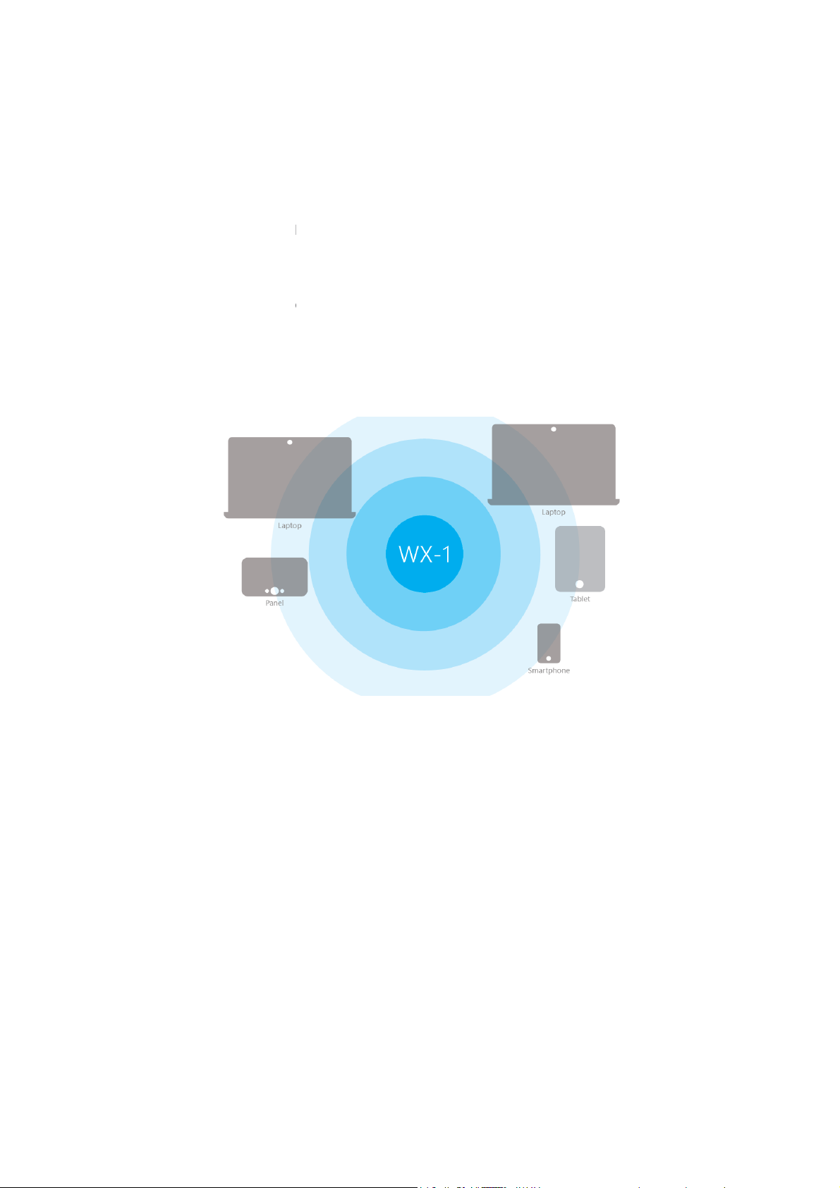
Introduction
Thank you for purchasing the Pakedge
As the central component of your wireless network
-
can choose their preferred source of wireless internet
mance of the wireless network.
GHz) of the
This is the typical configu
This mode is used to send wireless
cannot use an Ethernet cable directly. Let’s say you have a desktop computer in an isolated
portion of an old home and can’t run a cable through the whole house to get internet to that
provides you with high
band so that select
, improving the overall stability, reliability and
Fi networks, as shown below.
internet to a hardwired device when you
WX-1x 802.11ac Dual Band Access Point.
wireless AC networking. The WX
perfor
Each band (either 2.4 GHz or 5
• Access Point Mode:
, the WX-1
1x broadcasts on both the 2.4 GHz and 5 GHz
WX-1x can operate in three modes:
ration for most Wi-
-speed, high-range
devices
• WDS Bridge Mode:
specific computer.
Page 5
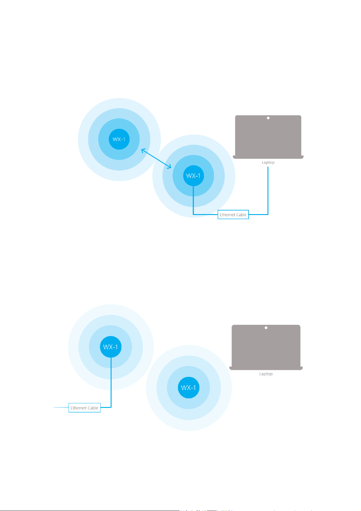
•
1
root access point mode and send it to a client device through an Ethernet connection.
The repeater also receives wireless signal from another access
unlike a brige access point, a repeater access point sends out Wi
x in bridge mode, it can receive a wireless signal from an access point in
Fi so that client devices can
When you put the WX-
• WDS Repeater –
connect to it wirelessly.
point. However,
-
Page 6

The functionality of the WX-1x changes depending on its operating mode. This manual offers both
general and mode-specific content.
Page 7
System Requirements
The minimum system requirements for the WX-1x are:
•
PC or MAC book compatible with an Ethernet interface
•
Operating system that supports an HTTP web browser
Hardware Installation
Note: the product is designed for specific application and must be professionally
installed by a qualified personal who has RF and related knowledge.
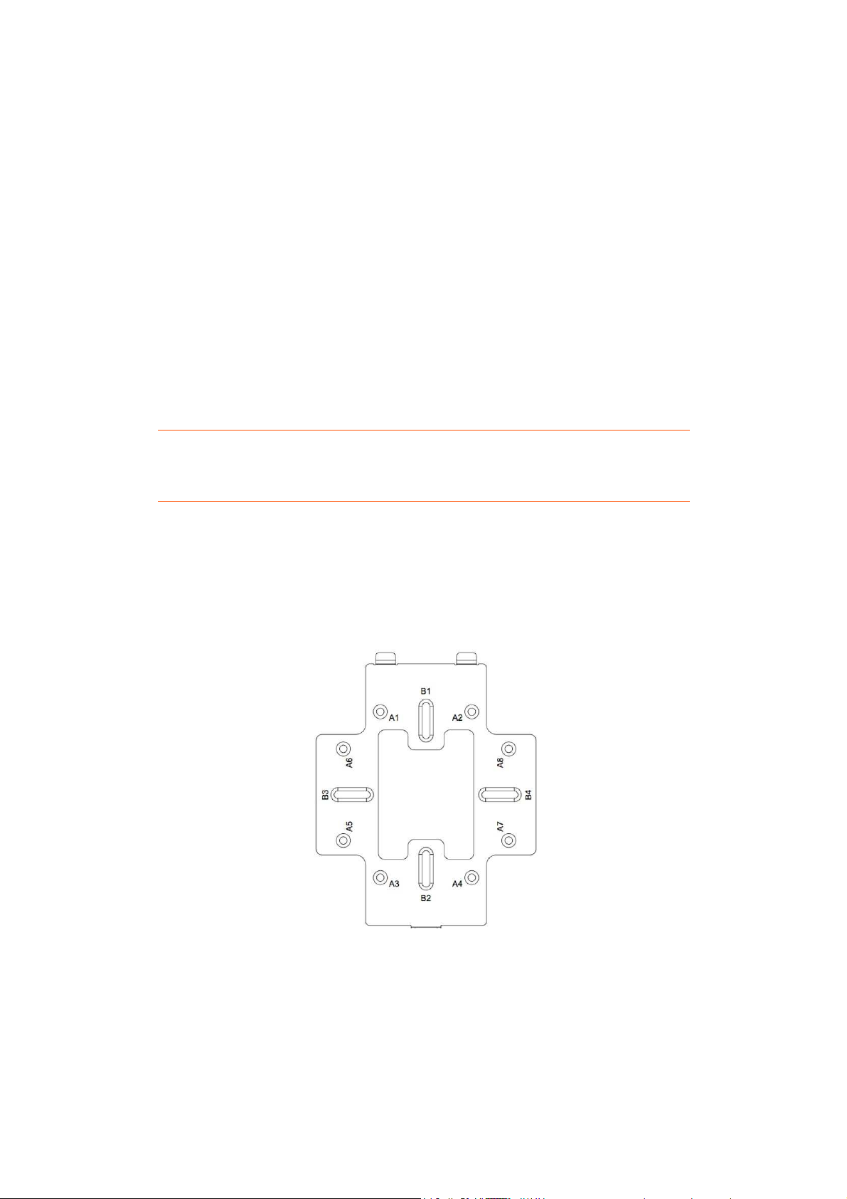
WX-1/WX-1-B Mounting Options
Using the Provided Wall Mount
A: DOUBLE-GANG ELECTRICAL BOX, WALL
B: WALL, SINGLE-GANG ELECTRICAL BOX, EUROPEAN OUTLET BOX US 4” ROUND JUNCTION BOX, US 3.5”
ROUND JUNCTION BOX
Page 8
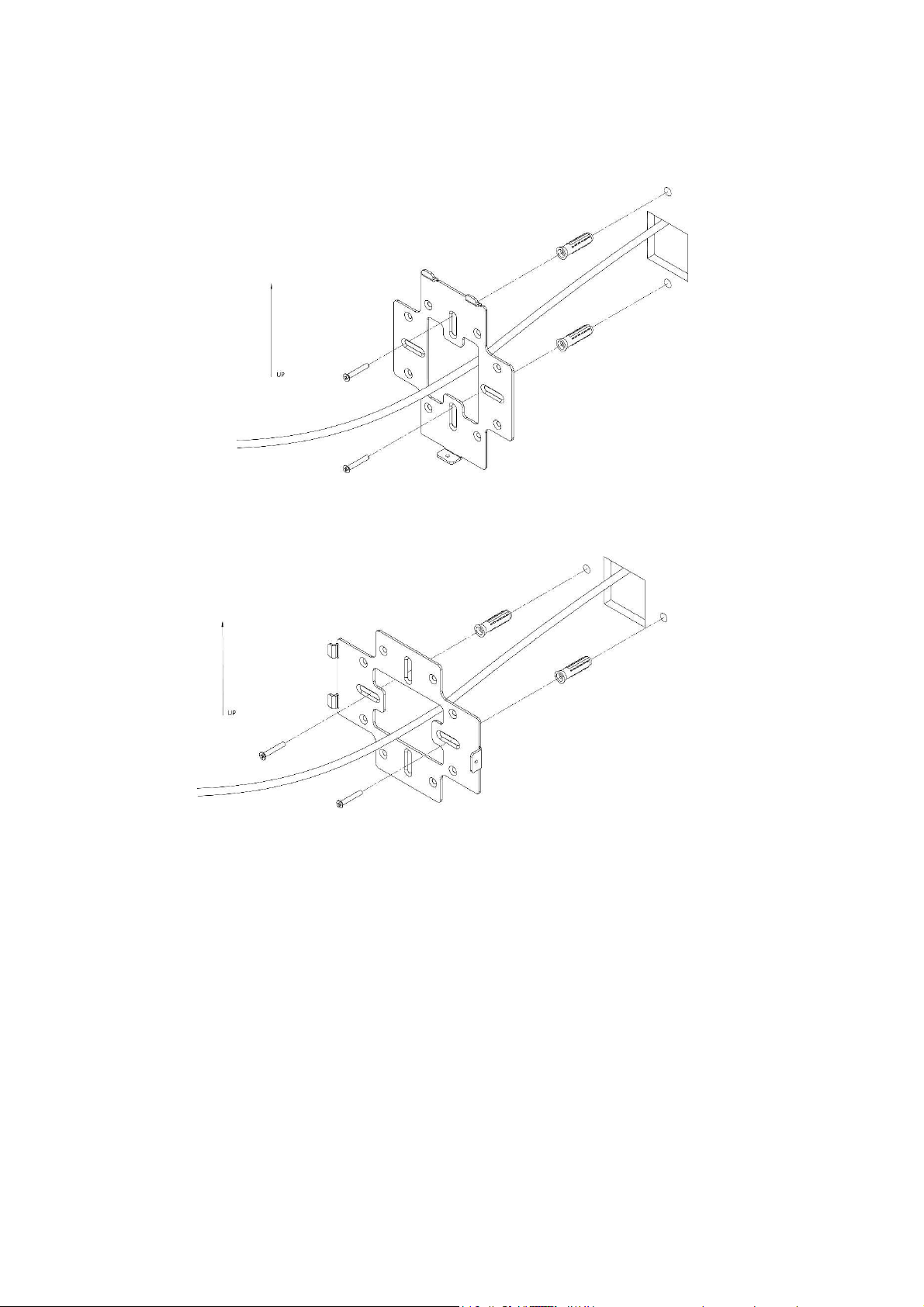
Vertical mount
Horizontal mount
hardware.
: Secure the wall bracket to the wall anchors using the included hardware.
: Line up the slots and secure the wall bracket to the wall anchors using the included
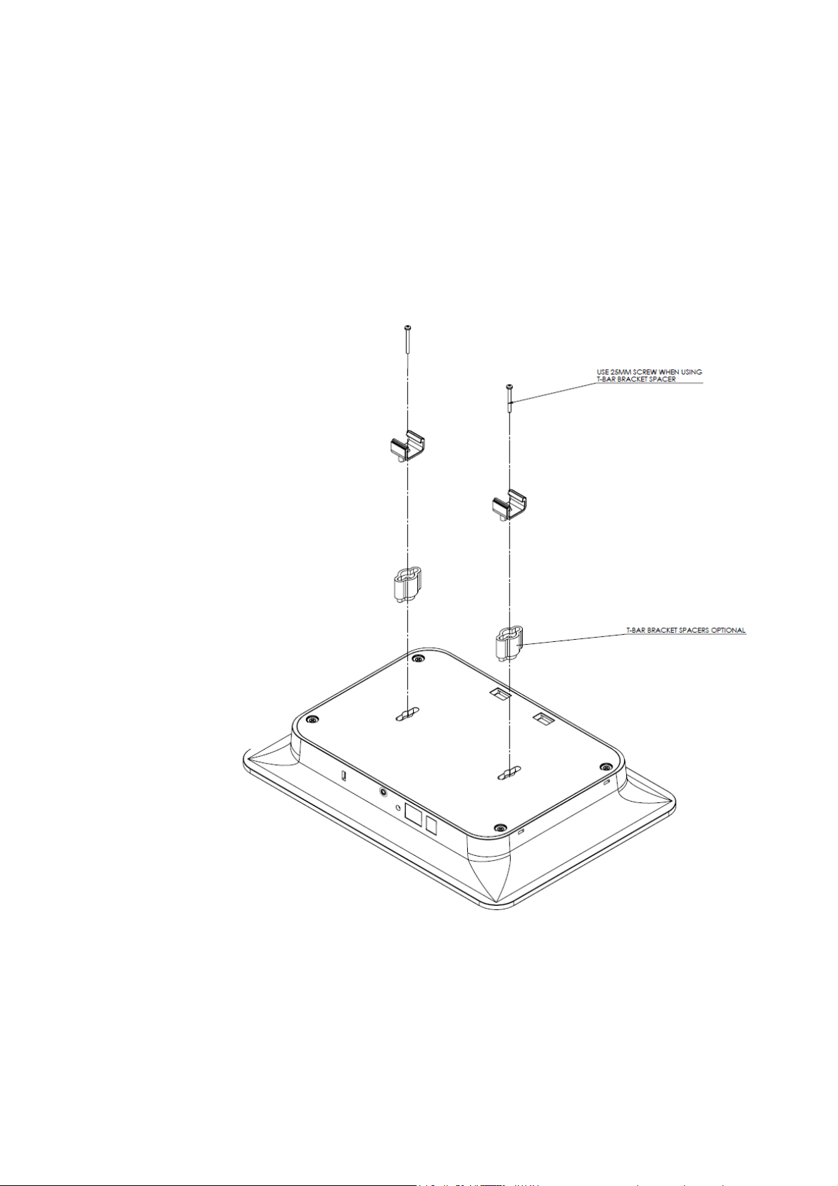
Using provide spacer to mount the Access Point (Optional)
In order to properly route the Ethernet cable to the unit use the provided spacer.
1. Attached the wall bracket to the spacer.
2. Route the cable through the spacer.
3. Screw the assembled unit to the wall.
Page 9
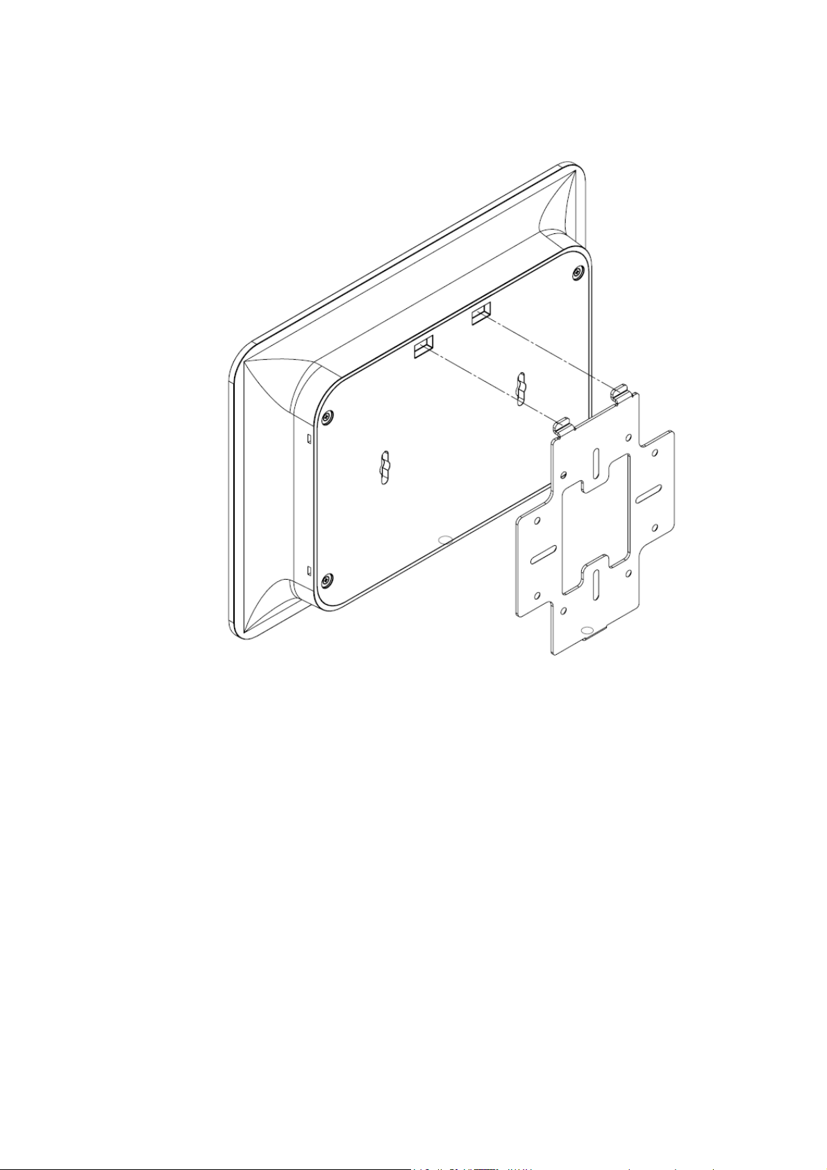
Line the two tabs on the top of the wall bracket with the two pockets on the back of the access point.
Slide the WAP downwards to lock it in place and secure with security screw.
Page 10
Page 11
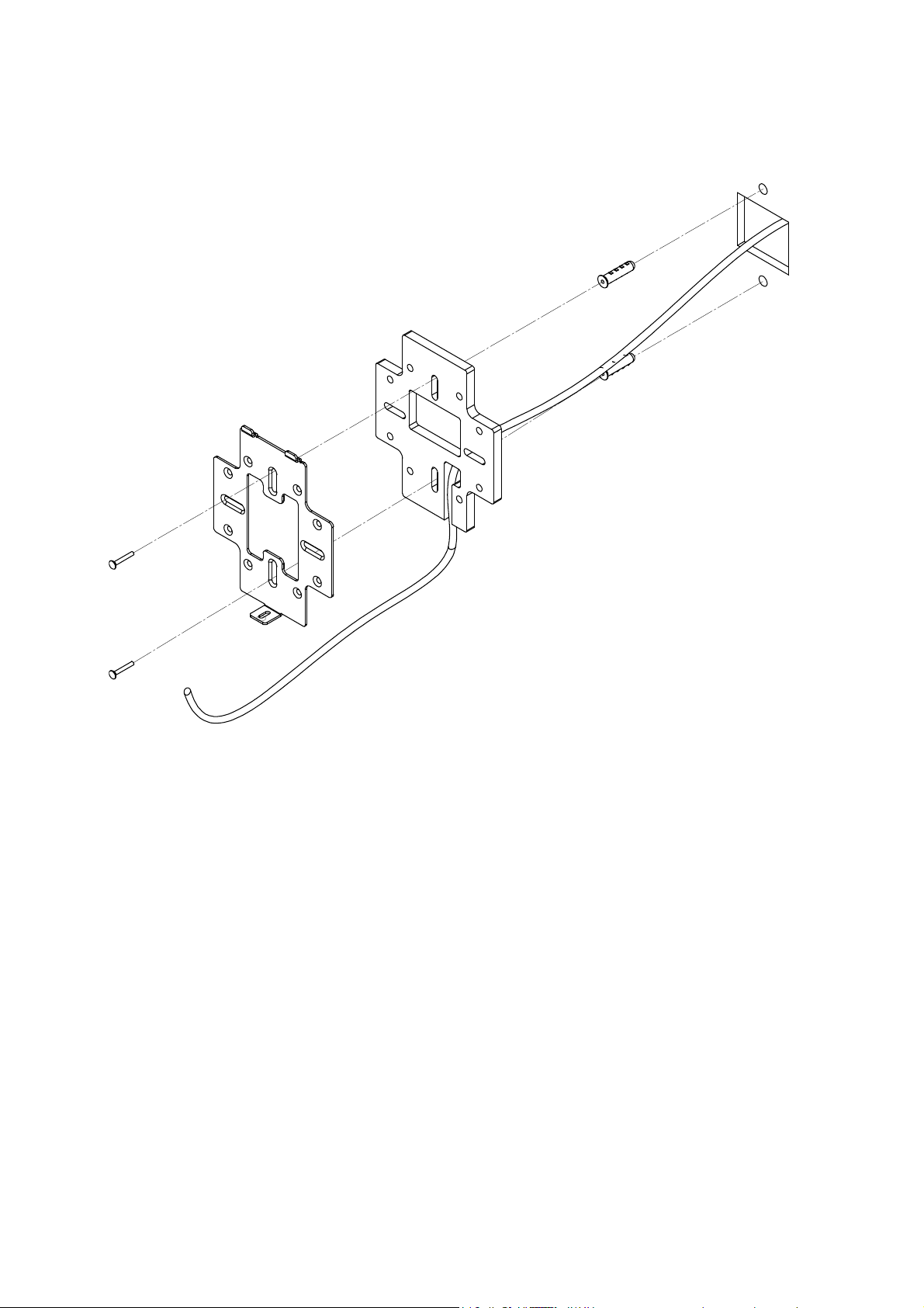
Using Provided T-bar
bar bracket into the slots on the back of the WAP and line up the two holes on the T
Bar Bracket with the two mounting points on the back of the WAP
racket to the WAP.
Using the supplied hardware,
1. Place the T-
mount the T-bar b
-
.
Page 12

2. Line up the T-
bar brackets with the T
bar brackets snap on.
-Bar. Press down until the T-
Page 13
Power Method for the WX
using a PoE
must be powered by
-1
WX
compliant Power over Ethernet
The diagrams below show
Note: the product
Power via PoE+ Injector
+ injector or a PoE+ switch to power the
802.3at -
(PoE+) injector or switch
-1x.
Page 14

Power via PoE+ Switch
Power using the included power adapter
Page 15

The WX-1x can be configured in several modes: Access Point, WDS Root Access Point, WDS Repeater or
WDS Bridge. When shipped from the factory, the WX-1x is set to Access Point mode. The default IP
address of the WX-1x is
192.168.1.250
and username/password of
pakedge/pakedgea.
In order to log into the WX-1x, you must first configure the TCP/IP settings of your PC/Notebook. Follow
these steps:
1. Under
Control Panel
, double-click
Network Connections
of your Network Interface Card (NIC). The Local Area Connection Properties dialog appears:
2. Select
Internet Protocol Version 4 (TCP/IPv4)
and click
Properties
dialog appears where you can configure the TCP/IP settings of your PC.
and double-click the connection
. The Internet Protocol (TCP/IP)
Page 16
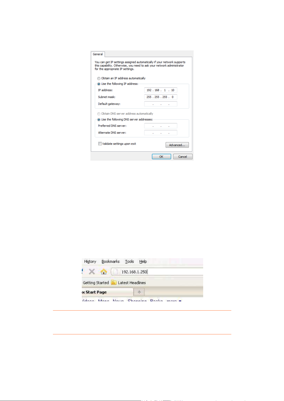
3. Select
Use the following IP Address
and type the IP address and subnet mask, as in the example
below. (Be sure the IP address and subnet mask are on the same subnet as the WX-1x.)
WX-1x IP address: 192.168.1.250
PC IP address: 192.168.1.10
PC subnet mask: 255.255.255.0
WX-1x Start Up
To configure the WX-1x through a web browser, type the IP address of the WX-1x (default
192.168.1.250
) and press
NOTE:
Enter
.
Make sure the WX-1x and your computer are configured on the same subnet.
To configure the IP address of your computer, follow the steps in the previous section.
The WX-1x login dialog appears.
Page 17

pakedge
x main menu appears (see figure below). The main menu displays
and general information such as the IP address, subnet mask, and MAC addresses.
the device operating mode,
SSIDs along with
and click
the current status
and
each SSID
In the username box, type
The WX-1
sections display
WX-1x supports multiple
. In the password box, type
wireless mode, channel bandwidth
details and security settings for
pakedgea
Login.
of WX-1x
The 2.4 GHz and 5 GHz
channel settings. The
.
Page 18

Menu Options
of the window comes with
the dashboard and logs of the
page that comes up when you log into the
: User can make changes to the network settings, such as the LAN, wireless settings, and
View diagnostics, enable SNMP, and control
Modify your personal account settings and upgate your firmware.
The dashboard is the default
The navigation bar on the top
•
Status: Shows
•
Network
transmit power settings.
•
Management:
•
Maintenance:
Status
4 options:
WX-1x access point.
WX-1x GUI.
your LEDs.
Page 19

Dashboard
The Dashboard is the default landing page of the access point. You can also access this page by hovering
icon and clicking
s and connected clients.
. This page displays the MAC and IP addresses
over the Status
mode, WLAN information, SSID
Dashboard
, operation
Page 20

System Log
has an activity log that can be used by Pakedge Technical Support for
:
External system log server
address of the external server.
port
Download the encrypted log.
value of the buffer is 10240 KB (10MB)
: An external server may be set up to receive log
: A port number for the external server may be entered here.
The System Log page
troubleshooting purposes.
•
System log buffer size
default setting.
•
•
External system log
•
Download:
Maximum
, which is also the
activity. Enter the IP
Page 21

Network
and
configure the IP address of your
using a DHCP client
. This page displays the LAN settings for
x with a static IP address
LAN
Hover over the Network icon
IP address automatically by
click LAN
WX-1x, you can configure the WX-1
.
the WX-1x. To
or obtain an
Page 22

LAN
: If your
Obtain an IP address automatically
Not recommended
Specify an IP address (default):
appropriate entries in the text boxes for
to apply the changes.
le this feature unless you need to
the access point will become inaccessible and will need to be
tagging can only be set on a managed switch capable of usin
for Management:
text box, enter the
x through. For example, if
to save your changes.
is connected to a DHCP server (such as a router), choose
ed an IP address from the
Select this option if you want to use a static IP address. Type the
Default Gateway
default VLAN on the access point
VLANs.
Enable under Management
VLAN you want to access the administrative
VLAN3 is used for management, type in 3.
•
IP Network Setting
“
DHCP pool (
•
and Secondary DNS.
•
Click “Apply”
Management VLAN
WX-1x
).
”. Your WX-1x will be assign
IP Address, IP Subnet Mask,
, Primary
Warning: Do not enab
If configured incorrectly,
default. VLAN
•
VLAN ID
VLAN.
•
In the VLAN ID
functions of the WX-1
•
Click Apply
tag the
To turn on VLAN Management, check
number of the
g
.
reset to factory
Page 23

Wireless
and click on
: Selecting your country is
After selecting your country and clicking Apply, the Country Code feature will
o regain access to Country Code,
, you will be directed to the Radio configuration page under
required for proper functionality of this device and may be
reset to factory default.
Radio
Hover over Network
the Radio tab.
•
Country Code
required by law.
become locked. T
Wireless
the access point must be
Page 24

•
Band Steering: Band steering steers 5Ghz capable clients to that frequency. By enabling this function,
the 2.4GHz SSID and settings will be copied to the 5GHz band.
•
Operation Mode: Both the 2.4 and the 5 GHz band have the following operating modes: Access Point,
WDS Root Access Point, WDS Repeater and WDS Bridge.
o
Access Point: Standard mode of operation. Allows a wireless connection to the LAN.
o
WDS Root Access Point: The access point with this mode set will be the “root” device that
access points configured with WDS Repeater and WDS Bridge will connect to.
o
WDS Repeater: This mode allows the access point to connect to a WDS Root Access Point.
This setting will take the SSID broadcasted by the WDS Root Access Point and rebroadcast it
to end user devices.
o
WDS Bridge: This mode allows the access point to connect to a WDS Root Access Point. This
mode takes in the SSID broadcasted by the WDS Root Access Point and turns it into Ethernet
connectivity for client devicess.
•
Wireless Mode: Choose the setting that corresponds to the type of wireless clients connected to your
network: B-Only, G-Only, B/G-Mixed, N/G-Mixed or B/G/N-Mixed (on the 2.4GHz) or A-Only, N-Only,
N/A-Mixed, AC-Only, AC/N-Mixed or A/AC/N-Mixed (on the 5GHz). If you aren’t sure which type(s) of
clients will access the wireless networks, it’s recommended to choose B/G/N-Mixed on the 2.4GHz
and A/AC/N-Mixed on the 5GHz for best performance.
NOTE: When set to a mixed mode, ALL devices connected to the wireless will use the
mode that is compatible for ALL devices. Example – If you have the 2.4GHz Wireless
set to B/G/N Mixed and all connected devices use G, the speeds will slow accordingly.
•
Channel Mode: By default, the Channel Mode is set to HT 20/40 MHz (when using 2.4GHz) and HT
80 MHz (when using 5GHz). Selecting the HT 40 MHz channel mode on 2.4 GHz will allow for greater
speeds, but at the risk of also increasing interference.
o
Example: When using the 20 MHz channel width on the 2.4GHz band, channel 6 would bleed
into channels 4, 5, 7 and 8 giving you three non-overlapping channels (1, 6 and 11). When
using 40MHz channel width on the 2.4GHz radio, channel 6 would bleed into channels 2, 3, 4,
5, 7, 8, 9, and 10.
•
Channel – Using the default setting (Auto), the WX-1x automatically selects the channel with best
performance for the wireless network. To select a channel manually, click the drop-down list and
select a channel. The channel options available depend on the Country Code selected.
Page 25

•
AP Detection – Click “Scan” to perform an automatic site survey. A new window will open and
display the site survey utility. The WX-1x will scan the frequency for devices currently broadcasting
their SSID, and then will display them in the table.
Page 26

Security Profiles
Under the Security Profiles
tab, you will be able to configure security profiles that can be used when
creating SSIDs under the configuration tab.
Create a name for the security profile.
lect an encryption type for your security profile
Encryption, WPA PSK, WPA2 PSK, and WPA/WPA2 PSK.
: This will leave your profile without security
: Password must be at least 8
(not recommended).
: Password must be at least 8 characters long. AES
(Recommended)
WPA/WPA2 PSK
d Mode and uses TKIP encryption.
NOTE: Passwords may only contain numbers and letters
allowed. Example
The four available options are, No
ecommended)
This is a legacy encryption
only encryption.
: Password must be at least 8 characters long. This feature is also known
Special characters are not
ecommended)
•
Profile Name:
•
Encryption: Se
o No Encryption
o WPA PSK
o WPA2 PSK
o
protocol
as Mixe
.
(not r
characters long.
-
.
s of special characters: (!@#$%:;^&*).
.
Page 27

Configuration
To configure SSIDs for both the 2.4 GHz and 5 GHz bands, go to
per band for a total of 16 SSID
: The SSID may be turned on or turned off using this checkbox.
: The SSID is the name associated with the W
: The profiles created under the Security Profiles tab may be applied to the SSID
this feature will keep the SSID
ilable for client access
: This feature is also referred to as “station separation”
SSID
uration
network. An SSID cannot
name from being broadcast
This is not a security feature.
This feature prevents
the network.
set up to 8 SSIDs
s.
the Config
tab. The WX-1x can
•
On Off
•
Wireless Name (SSID)
exceed 32 characters.
•
Security Profile
here.
•
Hide SSID: Enabling
be ava
•
Client Isolation
clients on the same
, provided the SSID is turned on.
from being able to access other clients on
i-Fi
. The SSID will still
.
Page 28

•
: This option defines the
, select the grey cir
with the available VLAN options.
isplay
Management VLAN. Management VLAN is located on the LAN page under Network.
Guest Network
The Guest Network feature is designed for networks that do not have a guest VLAN. The Guest
only has access to the internet. Each access point’s guest network is
the guest networks of other access points.
select On/Off. By default
set to 192.168.200.X. You have the optio
can change the SSID, IP address, subnet,
them.
on which the SSID will reside.
selection ring will appear
that were configured under
the guest network name is Pakedge
n to change the default settings, if desired. You
starting IP address and ending IP address. Once changes are
Pakedge Zone (VLAN)
change the VLAN
•
Manage: This column d
acts as its own network and
independent from
VLAN that
cle with the number 1 inside it. A
s the management settings
Settings
To
Network
To enable the Guest Network,
the IP scheme is
complete, click Apply to save
,
-Guest and
Page 29

SSID
: There is a guest network available on both the 2.4 GHz and 5 GHz band.
: This option turns the Guest Network on and off.
: The SSID of the Guest Network can be entered in this textbox.
: Select a
: Enter in the
: Select the class of the guest network
: This is the beginning of the DHCP range used on the guest network.
have multiple access points, you can give them the same DHCP range because the guest network
point will be independent of one another.
: This is the last IP address available o
: The DNS Server IP can be set to an external DNS or to the router’s IP address if
the router provides a DNS server.
security profile that has already been defined under the Security Profiles
255.255.255.0 is the standard set
the DHCP range
•
Radio
•
On/Off
•
Wireless Name (SSID)
•
Security Profile
tab.
Manual IP Settings
•
IP Address
•
Subnet Mask
selected by default.
IP address the access point will be used on.
.
ting and is
Manual IP Settings
•
Starting IP Address
of each access
•
Ending IP Address
•
DNS Server IP
If you
n
.
Page 30

Advanced
page, you can configure:
Transmit Power: The power depends on the distance of the devices in your wireless network. From the
down list, select the desired power. You can use this feature to limit the coverage area of the
Maximum: This setting will broadcast at the maximum allowed mW for the channel
selected if Obey Regulatory Power is checked. If Obey Regulatory Power is not checked,
then the maximum 30 dBm (1000 mW) will be broadcast.
setting will adjust the power of the access point based on the distance to
the furthest client device. The access point will lower its power if the furthest client is 10
feet away and will raise the power if the furthest client is 100 feet away.
broadcast at the selected power level.
This feature will enable government mandated power levels per channel based
on the access point’s Country Code.
: Enter the packet size threshold for RTS/CTS (Request to Send/Clear to
to occur. The primary reason for implementing this function is to minimize the collision between
hidden stations, which occurs when access points and wireless users
and there is a high occurrence of retransmissions on the wireless LAN. Default setting is 2347.
: Adjusting Beacon Interval will allow clients to sleep longer. Clients have to wake
up for every beacon, so this se
BP = 100 your stations are allowed to sleep for up to 100
These are static power settings. The access point will
are spread out in a location
tting tells your client how many milliseconds it can sleep for (e.g., if
On the Advanced
dropwireless network.
o
o Automatic: This
o 1 dBm (1 mW) –
Obey Regulatory Power:
•
RTS/CTS Threshold
30 dBm (1000 mW):
Send)
•
Beacon Interval
ms).
Page 31

Management
Page 32

Diagnostics
and click on
Target IP / Domain Name
to start the test.
ping test under the
: Enter the IP Address of a location to ping. 8.8.8.8 is a Google
Ping
Hover over Management
tab:
Diagnostics. You will be directed to the
Ping
•
Ping –
o
DNS server.
o Click Start
Page 33

Traceroute
A Traceroute test can help you identify obstacles you may have in the network. The Traceroute text maps
between the
an IP Address or Domain Name into the
test. If the test fails to complete or
x and the target location. To run a Traceroute test, enter
textbox and click
Click on the Traceroute tab.
the path for packets moving
WX-1
Target IP / Domain Name
takes too long, click Stop.
Start to begin the
Page 34

SNMP
and click on SNMP.
: Enter the physical location of the
contact information of the installer or network administrator for the SNMP
: Enter in a description of the device.
efault description is Pakedge
Hover over Management
•
Location
•
Contact: Enter the
manager.
•
Description
WX-1x as a reference.
The d
WX-1 WAP.
Page 35

LEDs
and click on LEDs.
: Check
Hover over Management
•
Turn off all LEDs
Maintenance
to turn LEDs off.
Page 36

Username/Password
and click on
and click on
. You can change the username and
up
Hover over Maintenance
password for the device here.
Time Zone
Username/Password
Hover over Maintenance
Time Zone. This page allows you to set
the timezone.
Page 37

you to update the firmware for the unit.
Selecting
Click Choose File to select the firmware file.
s the firmware with the file you selected.
: This feature will
s after the firmware update.
connected to the internet.
Firmware
Allows
•
•
•
•
Keep Settings:
Local Image:
Local Update: Update
Check Update
this will preserve your current configuration
only work if the WX-1x is
Page 38

and click on
: Click
to save and export the current settings of the
its
Configuration
Hover over Maintenance
•
Download backup
WX-1x.
•
Reset to defaults: Click
Configuration:
Download Configuration
Factory Default to reset the the WX-1x back to
factory default settings.
Page 39

•
Restore backup – Load a configuration file using the Browse button to restore the WX-1x to a
previous configuration.
Page 40

Reboot
and click on Reboot
licking the Reboot Button allows you to reboot the device.
Hover over Maintenance
C
.
Page 41

Appendix A – Specs
HARDWARE SPECIFICATIONS
•
1 x 10/100/1000 Gigabit Ethernet RJ-45 port with IEEE 802.3at Power over Ethernet (PoE+)
support
•
Configurable LED Indicators for Power, Ethernet, 2.4GHz Wireless and 5GHz Wireless
•
Power over Ethernet (PoE+) IEEE802.3at compliant
•
Power Supply: 100 to 240 VDC ± 10%, 50/60 Hz (depends on different countries)
•
DC input: 12V/2A
RF INFORMATION
•
Frequency Band:
o 802.11 B/G/N on 2.4 to 2.462GHz, which can be programed based on country regulations.
o 802.11 A/N/AC on 5 to 5.805GHz, which can be programed based on country regulations.
•
Operating Channels:
OPERATIONS
•
Operation Modes:
•
Up to 16 SSIDs
•
Supports 802.1q VLANs
•
Spanning Tree Supports 802.1d Spanning Tree Protocol
•
IP Auto-configuration – DHCP client
•
Transmission rate options:
o 2.4 GHz - 11 for North America, 13 for Europe, 14 for Japan
o 5 GHz – 24 channels depending on country
o 2.4/5 GHz have independent operation modes
o Access Point/ WDS Bridge/WDS AP/Repeater
Page 42

O 2.4 GHZ – B-ONLY, G-ONLY, B/G-MIXED, N-ONLY, G/N-MIXED, B/G/N-MIXED
O 5 GHZ – A-ONLY, N-ONLY, A/N MIXED, AC-ONLY, N/AC-MIXED, A/N/AC-MIXED
MANAGEMENT AND SECURITY
•
User can adjust power by dBm
•
Web-based configuration (HTTP)
•
Upgrade firmware via web browser/internet
•
Auto-channel selects the least congested channel
•
Backup and restoration settings available through web interface
•
QoS WMM
•
WPA-PSK/WPA2-PSK/ WPA/WPA2 Mixed using TKIP or AES
•
SSID broadcast can be enabled or disabled
•
WLAN L2 Isolation (AP mode only)
•
List of connected wireless clients available
ENVIRONMENT
•
Temperature Range
o Operating: 0ºC to 45ºC (32º to 113ºF)
o Storage: -20ºC to 60ºC (-4Fº to 140ºF)
•
Humidity (non-condensing)
o Operating: 90% or less
o Storage: 90% or less
MECHANICAL
Enclosure: 9.81 inches X 7.05 inches
o Depth: 1.51 inches
o Base 7.76 inches X 5.55 inches
Page 43

Appendix B – Accessory List
WX-1, WX-1-B
•
Quick Start Guide
•
AC100-240V, 50-60Hz DC12V 2A power adapter
•
CAT5e cable
•
Mounting bracket
•
T-bar mount
•
Screws
Appendix C – Technical Support
Please visit our website for up-to-date support information:
Website: www.pakedge.com
Email: support@pakedge.com
CONTACT INFORMATION:
Northern California Office
Pakedge Device & Software
3847 Breakwater Avenue
Hayward, CA 94545-3606
Southern California Office:
Pakedge Device & Software
17011 Beach Blvd. Suite 600
Huntington Beach, CA 92647-5946
Appendix D – Limited Warranty
Model WX-1x
Congratulations on your purchase of a Pakedge Device & Software wireless product! Pakedge designs
and manufactures the finest home networking products. With proper installation, setup, and care, you
Page 44

should enjoy many years of unparalleled performance. Please read this consumer protection plan carefully
and retain it with your other important documents.
This is a LIMITED WARRANTY as defined by the U.S. Consumer Product Warranty and Federal Trade
Commission Improvement Act.
What Is Covered Under the Terms of This Warranty
SERVICE LABOR: Pakedge will pay for service labor by an approved Pakedge service center when needed
as a result of manufacturing defect for a period of one (3) year from the effective date of delivery to the
end user.
PARTS: Pakedge will provide new or rebuilt replacement parts for parts that fail due to defects in
materials or workmanship for a period of one (1) year from the effective date of delivery to the end user.
Such replacement parts are then subsequently warranted for the remaining portion (if any) of the original
warranty period.
What Is Not Covered Under the Terms of This Warranty
This warranty only covers failure due to defects in materials and workmanship that occur during normal
use and does not cover normal maintenance. This warranty does not cover any appearance item; any
damage to living structure; failure resulting from accident (for example: flood, electrical shorts, insulation);
misuse, abuse, neglect, mishandling, misapplication, faulty or improper installation or setup adjustments;
improper maintenance, alteration, improper use of any input signal and/or power, damage due to
lightning or power line surges, spikes and brownouts; damage that occurs during shipping or transit; or
damage that is attributed to acts of God.
The foregoing limited warranty is Pakedge’ s sole warranty and is applicable only to Products sold as new
by Authorized Dealers. The remedies provided herein are in lieu of a) any and all other remedies and
warranties, whether expressed, implied or statutory, including but not limited to, any implied warranty of
merchantability, fitness for a particular purpose or non-infringement, and b) any and all obligations and
liabilities of Pakedge for damages including but not limited to incidental, consequential or special
damages, or any financial loss, lost profits or expense, or loss of network connection arising out of or in
connection with the purchase, use or performance of the Product, even if Pakedge has been advised of
the possibility of such damages.
CAUTION: DAMAGE RESULTING DIRECTLY OR INDIRECTLY FROM IMPROPER INSTALLATION OR SETUP IS
SPECIFICALLY EXCLUDED FROM COVERAGE UNDER THIS WARRRANTY. IT IS IMPERATIVE THAT
INSTALLTION AND SETUP WORK BE PERFORMED ONLY BY AN AUTHORIZED PAKEDGE DEALER TO
PROTECT YOUR RIGHTS UNDER THIS WARRANTY. THIS WILL ALSO ENSURE THAT YOU ENJOY THE FINE
PERFORMANCE YOUR PAKEDGE PRODUCT IS CAPABLE OF PROVIDING.
Rights, Limits, and Exclusions
Page 45

Pakedge limits its obligation under any implied warranties under state laws to a period not to exceed the
warranty period. There are no express warranties. Pakedge also excludes any obligation on its part for
incidental or consequential damages related to the failure of this product to function properly. Some
states do not allow limitations on how long an implied warranty lasts, and some states do not allow the
exclusion or limitation of incidental or consequential damages. In this case, the above limitations or
exclusions may not apply to you. This warranty gives you specific legal rights, and you may also have
other rights that vary from state to state.
Effective Warranty Date
This warranty begins on the effective date of delivery to the end user. For your convenience, keep the
original bill of sale as evidence of the purchase date from your authorized dealer.
Important- Warranty Registration
Please register your product at www.pakedge.com. It is imperative that Pakedge knows how to reach you
promptly if we should discover a safety problem or product update for which you must be notified. In
addition, you may be eligible for discounts on future upgrades as new networking standards come about.
To Obtain Service, Contact Your Pakedge Dealer.
Repairs made under the terms of the Limited Warranty covering your Pakedge product will be performed
by an Authorized Pakedge Service Center. These arrangements must be made through the selling
Pakedge Dealer. If this is not possible, contact Pakedge directly for further instructions. Prior to returning
a defective Product directly to Pakedge, you must obtain a Return Material Authorization number and
shipping instructions. Return shipping costs will be the responsibility of the owner.
For additional information about this warranty, visit our website at www.pakedge.com.
Federal Communication Commission Interference
Statement
This equipment has been tested and found to comply with the limits for a Class B digital device, pursuant
to Part 15 of the FCC Rules. These limits are designed to provide reasonable protection against harmful
interference in a residential installation. This equipment generates, uses and can radiate radio frequency
energy and, if not installed and used in accordance with the instructions, may cause harmful interference
to radio communications. However, there is no guarantee that interference will not occur in a particular
installation. If this equipment does cause harmful interference to radio or television reception, which can
be determined by turning the equipment off and on, the user is encouraged to try to correct the
interference by one of the following measures:
- Reorient or relocate the receiving antenna.
- Increase the separation between the equipment and receiver.
Page 46

- Connect the equipment into an outlet on a circuit different from that to which the
receiver is connected.
- Consult the dealer or an experienced radio/TV technician for help.
FCC Caution: Any changes or modifications not expressly approved by the party responsible for
compliance could void the user's authority to operate this equipment.
This device complies with Part 15 of the FCC Rules. Operation is subject to the following two conditions:
(1) This device may not cause harmful interference, and (2) this device must accept any interference
received, including interference that may cause undesired operation.
This transmitter must not be co-located or operating in conjunction with any other antenna or transmitter.
For operation within 5.15 ~ 5.25GHz / 5.47 ~5.725GHz frequency range, it is restricted to indoor
environment. The band from 5600-5650MHz will be disabled by the software during the manufacturing
and cannot be changed by the end user. This device meets all the other requirements specified in Part 15E,
Section 15.407 of the FCC Rules.
IMPORTANT NOTE:
FCC Radiation Exposure Statement:
This equipment complies with FCC radiation exposure limits set forth for an uncontrolled environment.
This equipment should be installed and operated with minimum distance 25cm between the radiator &
your body.
Industry Canada statement:
This device complies with RSS-247 of the Industry Canada Rules. Operation is subject to the following two
conditions: (1) This device may not cause harmful interference, and (2) this device must accept any
interference received, including interference that may cause undesired operation.
Ce dispositif est conforme à la norme CNR-247 d'Industrie Canada applicable aux appareils radio exempts
de licence. Son fonctionnement est sujet aux deux conditions suivantes: (1) le dispositif ne doit pas
produire de brouillage préjudiciable, et (2) ce dispositif doit accepter tout brouillage reçu, y compris un
brouillage susceptible de provoquer un fonctionnement indésirable.
Caution :
(i) the device for operation in the band 5150-5250 MHz is only for indoor use to reduce the potential for
harmful interference to co-channel mobile satellite systems;
(ii) the maximum antenna gain permitted for devices in the bands 5250-5350MHz and 5470-5725MHz shall
be such that the equipment still complies with the e.i.r.p. limit;
Page 47

(iii) the maximum antenna gain permitted for devices in the band 5725-5850MHz shall be such that the
equipment still complies with the e.i.r.p. limits specified for point-to-point and non-point-to-point
operation as appropriate; and
(iv) the worst-case tilt angle(s) necessary to remain compliant with the e.i.r.p. elevation mask requirement
set forth in Section 6.2.2(3) shall be clearly indicated.
(v) Users should also be advised that high-power radars are allocated as primary users (i.e. priority users)
of the bands 5250-5350MHz and 5650-5850MHz and that these radars could cause interference and/or
damage to LE-LAN devices.
Avertissement:
Le guide d’utilisation des dispositifs pour réseaux locaux doit inclure des instructions précises sur les
restrictions susmentionnées, notamment :
(i) les dispositifs fonctionnant dans la bande 5150-5250MHz sont réservés uniquement pour une
utilisation à l’intérieur afin de réduire les risques de brouillage préjudiciable aux systèmes de satellites
mobiles utilisant les mêmes canaux;
(ii) le gain maximal d'antenne permis pour les dispositifs utilisant les bandes de 5250 à 5350MHz et de
5470 à 5725MHz doit être conforme à la limite de la p.i.r.e;
(iii) le gain maximal d'antenne permis (pour les dispositifs utilisant la bande de 5725 à 5850MHz) doit être
conforme à la limite de la p.i.r.e. spécifiée pour l'exploitation point à point et l’exploitation non point à
point, selon le cas;
(iv) les pires angles d’inclinaison nécessaires pour rester conforme à l’exigence de la p.i.r.e. applicable au
masque d’élévation, et énoncée à la section 6.2.2 3), doivent être clairement indiqués.
(v) De plus, les utilisateurs devraient aussi être avisés que les utilisateurs de radars de haute puissance
sont désignés utilisateurs principaux (c.-à-d., qu’ils ont la priorité) pour les bandes 5250-5350 MHz et
5650-5850 MHz et que ces radars pourraient causer du brouillage et/ou des dommages aux dispositifs
LAN-EL.
Radiation Exposure Statement:
This equipment complies with IC radiation exposure limits set forth for an uncontrolled environment. This
equipment should be installed and operated with minimum distance 30cm between the radiator & your
body.
Déclaration d'exposition aux radiations:
Cet équipement est conforme aux limites d'exposition aux rayonnements IC établies pour un
environnement non contrôlé. Cet équipement doit être installé et utilisé avec un minimum de 30cm de
distance entre la source de rayonnement et votre corps.
Page 48

Europe – EU Declaration of Conformity
Česky
[Jméno výrobce]
tímto prohlašuje, že tento
[typ zařízení]
je ve shodě se základními
This device complies with the essential requirements of the R&TTE Directive 1999/5/EC. The following test
methods have been applied in order to prove presumption of conformity with the essential requirements
of the R&TTE Directive 1999/5/EC:
- EN60950-1
Safety of Information Technology Equipment
- EN50385
Generic standard to demonstrate the compliance of electronic and electrical apparatus with the basic
restrictions related to human exposure to electromagnetic fields (0 Hz - 300 GHz)
- EN 300 328
Electromagnetic compatibility and Radio spectrum Matters (ERM); Wideband Transmission systems;
Data transmission equipment operating in the 2,4 GHz ISM band and using spread spectrum
modulation techniques; Harmonized EN covering essential requirements under article 3.2 of the
R&TTE Directive
- EN 301 893
Broadband Radio Access Networks (BRAN); 5 GHz high performance RLAN; Harmonized EN covering
essential requirements of article 3.2 of the R&TTE Directive
- EN 301 489-1
Electromagnetic compatibility and Radio Spectrum Matters (ERM); ElectroMagnetic Compatibility
(EMC) standard for radio equipment and services; Part 1: Common technical requirements
- EN 301 489-17
Electromagnetic compatibility and Radio spectrum Matters (ERM); ElectroMagnetic Compatibility
(EMC) standard for radio equipment and services; Part 17: Specific conditions for 2,4 GHz wideband
transmission systems and 5 GHz high performance RLAN equipment
This device is a 5GHz wideband transmission system (transceiver), intended for use in all EU member
states and EFTA countries, except in France and Italy where restrictive use applies.
In Italy the end-user should apply for a license at the national spectrum authorities in order to obtain
authorization to use the device for setting up outdoor radio links and/or for supplying public access to
telecommunications and/or network services.
Page 49

[Czech]
požadavky a dalšími příslušnými ustanoveními směrnice 1999/5/ES.
Dansk
[Danish]
Undertegnede
[fabrikantens navn]
erklærer herved, at følgende udstyr
[udstyrets
Deutsch
Hiermit erklärt
[Name des
Herstellers]
, dass sich das Gerät
[Gerätetyp]
in
Eesti
Käesolevaga kinnitab
[tootja nimi =
n
ame of manufacturer]
seadme
[seadme tüüp = type
English
Hereby,
[name of manufacturer]
, declares that this
[type of equipment]
is in compliance
Español
Por medio de la presente
[nombre del fabricante]
declara que el
[clase de equipo]
cumple
ΜΕ ΤΗΝ ΠΑΡΟΥΣΑ
[name of manufacturer]
∆ΗΛΩΝΕΙ ΟΤΙ
[type of equipment]
Français
Par la présente
[nom du fabricant]
déclare que l'appareil
[type d'appareil]
est conforme
Italiano
Con la presente
[nome del costruttore]
dichiara che questo
[tipo di apparecchio]
è
Latviski
Ar šo
[name of manufacturer
/ izgatavotāja nosaukums
]
deklarē, ka
[type of equipment /
Lietuvių
Šiuo
[manufacturer name]
deklaruoja, kad šis
[equipment type]
atitinka esminius
Hierbij verklaart
[naam van de fabrikant]
dat het toestel
[type van toestel]
in
typebetegnelse]
1999/5/EF.
overholder de væsentlige krav og øvrige relevante krav i direktiv
[German]
[Estonian]
[Spanish]
Ελληνική
[Greek]
[French]
Übereinstimmung mit den grundlegenden Anforderungen und den übrigen
einschlägigen Bestimmungen der Richtlinie 1999/5/EG befindet.
of equipment]
vastavust direktiivi 1999/5/EÜ põhinõuetele ja nimetatud direktiivist
tulenevatele teistele asjakohastele sätetele.
with the essential requirements and other relevant provisions of Directive 1999/5/EC.
con los requisitos esenciales y cualesquiera otras disposiciones aplicables o exigibles de
la Directiva 1999/5/CE.
ΣΥΜΜΟΡΦΩΝΕΤΑΙ ΠΡΟΣ ΤΙΣ ΟΥΣΙΩ∆ΕΙΣ ΑΠΑΙΤΗΣΕΙΣ ΚΑΙ ΤΙΣ ΛΟΙΠΕΣ ΣΧΕΤΙΚΕΣ
∆ΙΑΤΑΞΕΙΣ ΤΗΣ Ο∆ΗΓΙΑΣ 1999/5/ΕΚ.
aux exigences essentielles et aux autres dispositions pertinentes de la directive
1999/5/CE.
[Italian]
[Latvian]
[Lithuanian
]
Nederlands
[Dutch]
conforme ai requisiti essenziali ed alle altre disposizioni pertinenti stabilite dalla direttiva
1999/5/CE.
iekārtas tips]
atbilst Direktīvas 1999/5/EK būtiskajām prasībām un citiem ar to
saistītajiem noteikumiem.
reikalavimus ir kitas 1999/5/EB Direktyvos nuostatas.
overeenstemming is met de essentiële eisen en de andere relevante bepalingen van
richtlijn 1999/5/EG.
Page 50

Malti
[Maltese]
Hawnhekk,
[isem tal
-manifattur]
, jiddikjara li dan
[il-mudel tal
-
prodott]
jikkonforma mal
-
Magyar
Alulírott,
[
gyártó neve
]
nyilatkozom, hogy a
[
... típus
]
megfelel a vonatkozó alapvetõ
Polski
Niniejszym
[nazwa producenta]
oświadcza, że
[nazwa wyrobu]
jest zgodny z
[Nome do fabricante]
declara que este
[tipo de equipa
mento]
está conforme com os
[Ime proizvajalca]
izjavlja, da je ta
[tip opreme]
v skladu z bistvenimi zahtevami in
[Meno výrobcu]
týmto vyhlasuje, že
[
typ zariadenia
]
spĺňa
základné požiadavky a všetky
Suo
mi
[Valmistaja
=
manufacturer]
vakuuttaa täten että
[type of equipment = laitteen
Svenska
Härmed intygar
[företag]
att denna
[utrustningstyp]
står I
överensstämmelse med de
ħtiġijiet essenzjali u ma provvedimenti oħrajn relevanti li hemm fid-Dirrettiva 1999/5/EC.
[Hungarian
]
[Polish]
Português
[Portugues
e]
Slovensko
[Slovenian]
Slovensky
[Slovak]
[Finnish]
követelményeknek és az 1999/5/EC irányelv egyéb elõírásainak.
zasadniczymi wymogami oraz pozostałymi stosownymi postanowieniami Dyrektywy
1999/5/EC.
requisitos essenciais e outras disposições da Directiva 1999/5/CE.
ostalimi relevantnimi določili direktive 1999/5/ES.
príslušné ustanovenia Smernice 1999/5/ES.
tyyppimerkintä]
koskevien direktiivin muiden ehtojen mukainen.
tyyppinen laite on direktiivin 1999/5/EY oleellisten vaatimusten ja sitä
[Swedish]
väsentliga egenskapskrav och övriga relevanta bestämmelser som framgår av direktiv
1999/5/EG.
Statement on UL certification
“This product is listed to applicable UL Standards and requirements by UL.”
Page 51

3847 Breakwater
Avenue
17011 Beach Blvd. Suite 600
Hayward, CA 94545
Huntington Beach, CA 92647
(650) 385-8702
www.pakedge.com
sales@pakedge.com
 Loading...