

Page 1
DS2 MINI
Page 2

2
Read this manual carefully before using the product and follow the instructions and
recommendations included herein. Refer to ctrl4.co/ds2mini for full documentation on this IP
intercom.
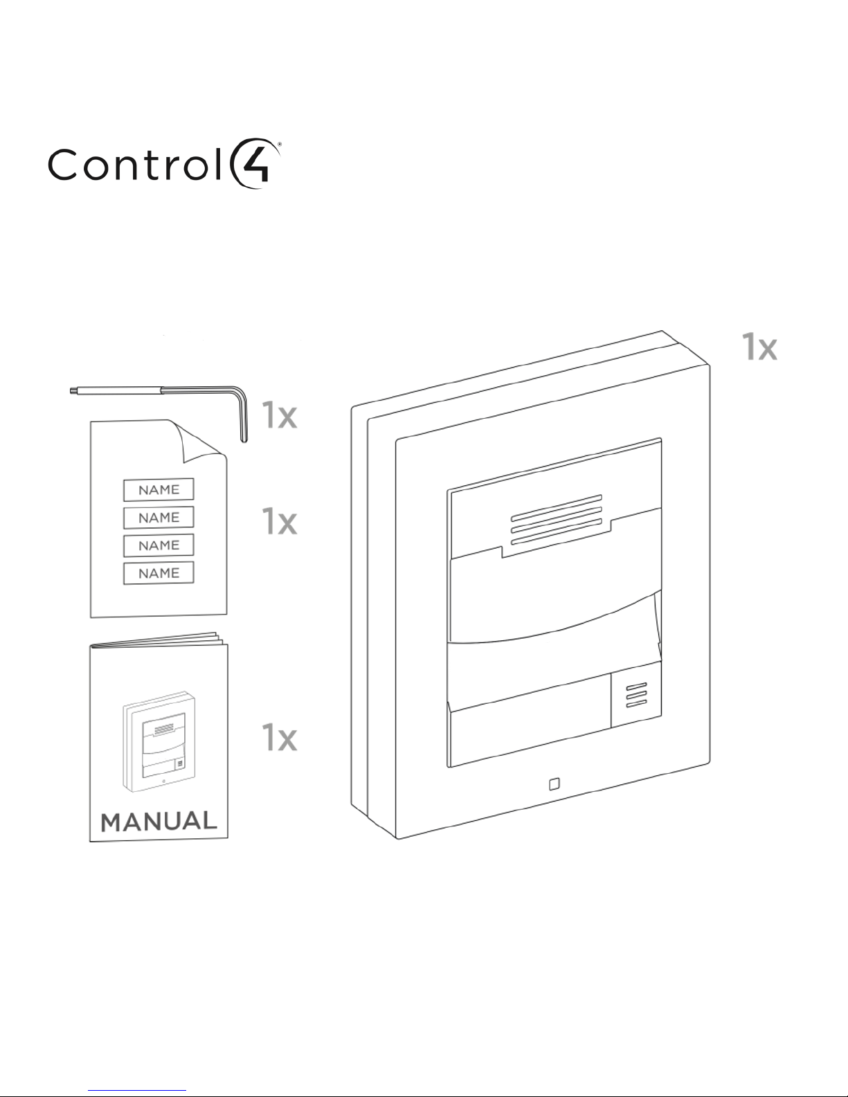
What you need for mounting
- LAN connection, Cat5e or higher UTP cable with RJ-45 connector
- PoE 802.3af or 12VDC/2A power supply
Installation procedure
1. Choose an installation site easily accessible to users.
2. Check the cable connection options.
3. Prepare the cables, LAN connection, power supply and lock/accessory wiring, if
necessary.
4. Remove the device from the package and install it as instructed in these
instructions.
5. Connect the cables and make sure that the device works correctly.
6. Mount the device to the base.
Caution
- When the proper mounting instructions are not met, water might get in and destroy the
electronics. The intercom circuits are constantly powered and water infiltration causes
an electro-chemical reaction. The manufacturer‘s warranty will be void for products
damaged in this way!
Electric installation–Description of connector terminals
Description of motherboard connectors accessible to users:
- 802.3af LAN connector
- IN1 input terminals in passive/active mode (-30 to +30VDC)
OFF = open contact OR UIN > 1.5V
ON = closed contact OR UIN < 1.5V
- OUT1 active output: 8 up to 12VDC, depending on the power supply (PoE: 10V;
adapter: supply voltage -2V), up to 400mA
- RELAY terminals for 30V/1A AC/DC NO/NC contact
- External 12/2A DC power supply terminals
- Grounding terminal
- RESET and FACTORY RESET button
- LED state indicators (red / device state / green – Ethernet connection / yellow – LAN
activity)
Page 3
3
Door lock connection–Either connect the electric lock to the Active output, which also
provides power, or switch the external power supply using a relay. In either case, we
recommend that you to use low-power locks and keep the above-mentioned maximum
values.
Where coil-containing devices such as relays or electromagnetic locks are used, make sure
that the intercom output is protected against surge when the induction load is switched off.
For this method of protection, we recommend a 1A/1,000V (e.g., 1N4007, 1N5407, 1N5408)
diode connected antiparallel and placed as close as possible to the lock.
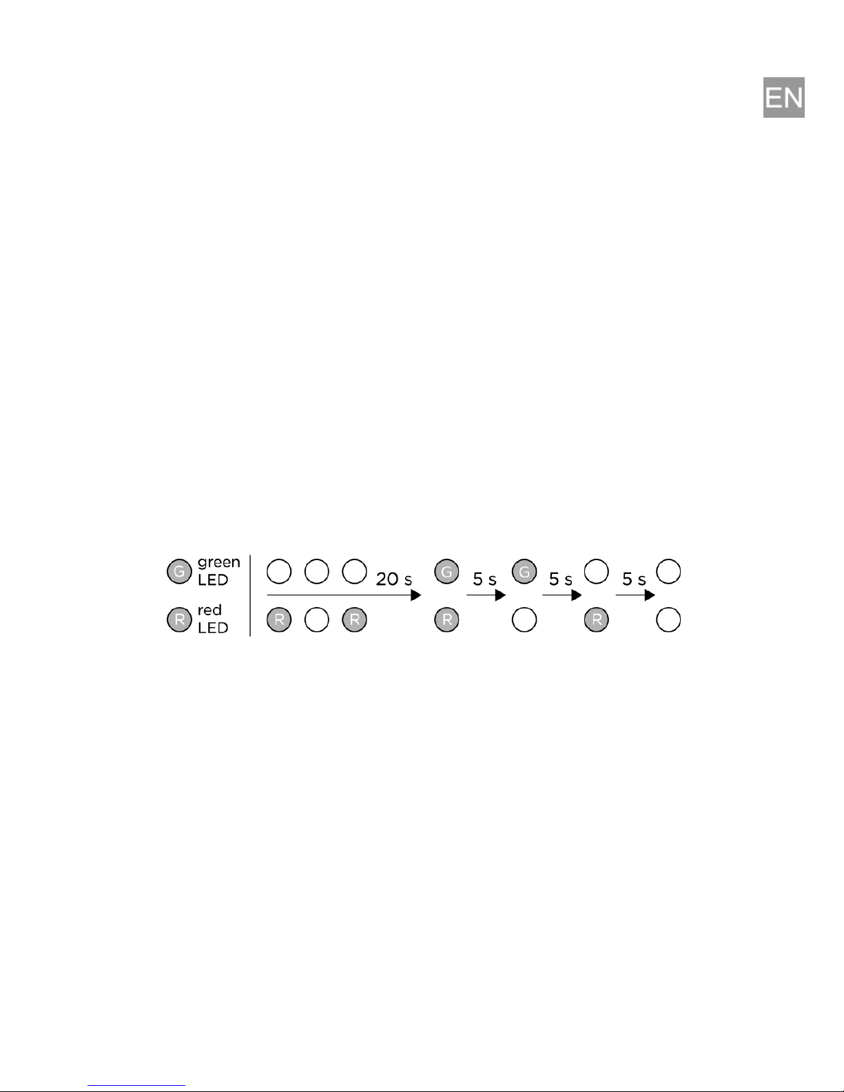
Restoring factory defaults–Follow the instructions below to reset the factory default
values:
Press the RESET button.
Wait until the red and green LEDs on the device come on simultaneously
(about 20 s).
Wait until the red LED turns off (about 5 s).
Wait until the green LED turns off and the red LED turns on again (about 5 s).
Wait until the red LED turns off (another 5 s).
Release the RESET button.
IP address:
Default setting is DHCP ON.
To switch DHCP ON/OFF, press the dial button 15x within 30 seconds from bootup.
Press the dial button 4x within three seconds to identify the door station to Control4.
Maintenance–Cleaning
The device surface can get dirty when used frequently. Use a piece of soft cloth moistened
with clean water to clean the device.
Page 4

4
Follow the principles below while cleaning:
Do not use aggressive detergents (such as abrasives or strong disinfectants).
Use appropriate cleaning agents (suitable for glasses, optical devices, screens, etc.)
for lens cleaning. Alcohol-based cleaners should not be applied.
Clean the device in dry weather in order to make waste water evaporate quickly. We
recommend using IT cleaning wipes.
Caution
- Use the product for the purpose it was designed and manufactured for, in compliance
with the user documentation.
- Any use of the product that is in contradiction with the instructions included in the user
manual may result in malfunction, damage, or destruction of the product.
- Any use or connection of the product other than that included herein shall be considered
undue and the manufacturer shall not be liable for any consequences arisen as a result
of such misconduct.
- Be careful while handling the product; the manufacturer shall not be liable for any
personal injury or property damage associated with the device.
- The warranty does not apply to the product defects and failures arisen as a result of
improper mounting (in contradiction with these instructions). The manufacturer is not
liable for damage caused by theft within an area that is accessible after the attached
electric lock is switched on. The product is not designed as a burglar protection device
except when used in combination with a standard lock, which has the security function.
- This manual is a brief version of the online Installation Manual available at
ctrl4.co/ds2mini. Should there be discrepancies, the online version prevails.
Declarations of Conformity
Hereby we, Control4 Corporation, declare that the product Control4 DS2 Door Station Mini is
in compliance with the essential requirements and other relevant provisions of Directive
1999/5/EC.
This equipment has been tested and found to comply with the limits for a Class B digital
device, pursuant to part 15 of the FCC Rules. This Class B digital apparatus complies with
Canadian ICES-003.
This product has been tested and found to comply with the limits of IEC 60950-1:2005
(Second Edition) and has received MET mark as the NRTL’s certification mark for the North
American Product Safety Requirements.
For the full wording of these declarations, see www.control4.com.
Page 5

Protocol
Signalling protocol: SIP 2.0 (RFC-3261)
Buttons
Button with white backlight and easily removable label
Audio
Microphone: 1 built-in microphone
Speaker: 2W, 4 ohm
Sound pressure at 1 kHz at 1 m distance: 78 dB
Audio stream
Codecs: G.711, G.729, G.722, L16/16 kHz
Camera
Resolution – JPEG: 1280 x 960 px
Resolution – video call: 640 x 480 px
Viewing angle: 120° (H), 90° (V), 145° (D)
Night vision: Yes
Video stream
Codecs: H.263+, H.263, H.264, MJPEG, MPEG-4
Interfaces
Power supply: 12V ± 15 % / 2A DC or PoE
PoE: PoE 802.3af (Class 0–12.95 W)
LAN: 10/100BASE-TX with Auto-MDIX, RJ-45
Switch output: NC/NO contacts, max. 30V / 1A AC/DC
Active switch output: 8 to 12VDC depending on power supply (PoE: 10V;
adapter: source voltage minus 2V), max. 400mA
Page 6

Mechanical properties
Operating temperature: -40°F to 140°F (-40°C to 60°C)
Storage temperature: -40°F to 158°F (-40°C to 70°C)
Operating relative humidity: 10% to 95% (non-condensing)
Officially certified outdoor coverage level: IP54, IK08
Dimensions
Frame for surface installation – 1 module: 107 x 130 x 28 mm (4.21 x 5.12 x
1.10 inches)
Frame for flush installation – 1 module: 130 x 153 x 5 mm (5.12 x 6.02 x 0.20
inches)
Page 7

Page 8

Control4 Corporation
11734 South Election Road
Salt Lake City, UT 84020
USA
2294v1
 Loading...