

Page 1
7" and 10" T3 Series In-Wall Touch Screen
Installation Guide
Supported models
• C4-WALL7-BL 7" T3-7 In-Wall Touch Screen, Black
• C4-WALL7-WH 7" T3-7 In-Wall Touch Screen, White
• C4-WALL10-BL 10" T3-10 In-Wall Touch Screen, Black
• C4-WALL10-WH 10" T3-10 In-Wall Touch Screen, White
Introduction
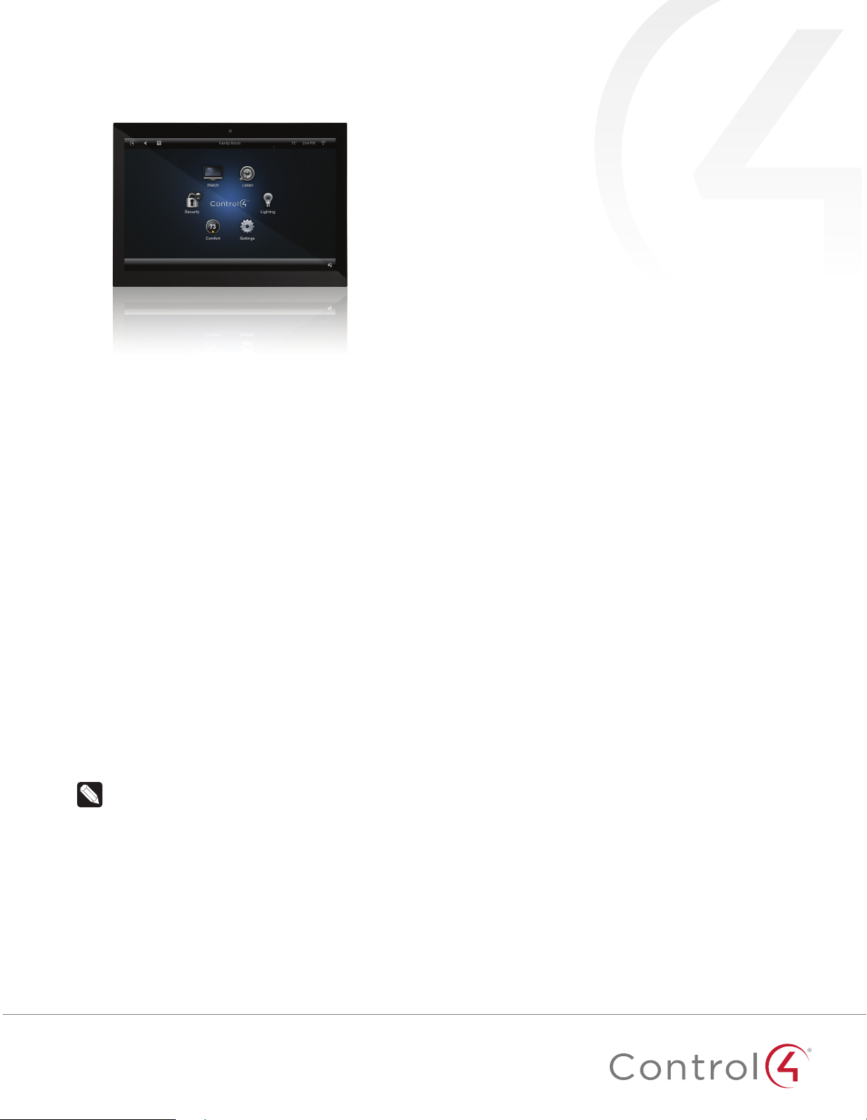
The Control4® T3-7 (7") and T3-10 (10") In-Wall Touch Screens
oer complete system control in an elegant and compact design.
The touch screens are equipped with a full capacitive screen,
audio and video Intercom (with the built-in camera) using SIP,
and more.
This touch screen works great in either new construction or
retrofit installations. For power and network connectivity, choose
from three options:
• Ethernet with PoE—The Ethernet network connection is
provided through the PoE Injector. No additional wiring is
needed.
• Ethernet with AC—Connect the touch screen to one of the
RJ-45 LAN ports on the gateway/router using the RJ-45
Ethernet cable. AC power is used to power the touch screen.
• WiFi with AC—The internal WiFi will communicate with the
LAN’s WAP. If the LAN has a WAP set up, no additional
network wiring is needed. AC power is used to power the
touch screen.
Note: 802.11b is not recommended for Video Intercom.
We recommend using Wireless-N. See “Specifications”
and “Power and Network Installation Options” for more
information.
Accessories available for purchase
• PoE. Control4 Power over Ethernet Injector, sold separately
(AC-POE1-B).
• Back box options (sold separately)—Metal and plastic, for
new construction or retrofit installations.
• 7" and 10" In-Wall Touch Screen Back Box Kits - New
Construction
• 7" and 10" In-Wall Touch Screens Wall Box, New
Construction, Plastic (C4-NWB57C-P)
• 7" and 10" In-Wall Touch Screens Wall Box, New
Construction, Metal (C4-NWB57C-M)
• 7" and 10" In-Wall Touch Screen Back Box Kit - Retrofit
• 7" and 10” In-Wall Touch Screens Wall Box, Retrofit,
Plastic (C4-RWB57C-P)
• 7" and 10" In-Wall Touch Screens Wall Box, Retrofit,
Metal (C4-RWB57C-M)
For back box installation details, see:
• 7" or 10" In-Wall Touch Screen Wall Box Installation
Guide-New Construction
• 7", or 10" In-Wall Touch Screen Wall Box Installation
Guide-Retrofit
Box contents
• 7" or 10" T3-7/T3-10 In-Wall Touch Screen
• Power box (to power the touch screen) (005-00065)
• Two screws (to attach the power box)
• Touch Screen removal tool
• Four adhesive-backed foam pads
• Warranty card
11
Page 2
Warnings
Warning! The touch screen must be protected by an
external circuit breaker or a fuse rated at 6A maximum
when used in Europe.
AVERTISSEMENT ! Pour réduire le risque du feu ou de
choc électrique, n’exposez pas cet appareil à la pluie ou
à l’humidité.
Warning! Do not place the touch screen near sources of
heat or expose to direct sunlight for an extended period
of time.
AVERTISSEMENT ! Ne placez pas l’unité près des
sources de chaleur ou exposition pour diriger la lumière
du soleil pendant une période prolongée.
Warning! Install in accordance with all national, state,
and local electrical codes.
AVERTISSEMENT ! Installez selon tous les national, état,
et codes électriques locaux.
Warning! This product generates heat. The room must
have adequate ventilation or the ability to dissipate heat
eectively.
AVERTISSEMENT ! Ce produit produit de la chaleur.
La salle doit avoir à ventilation proportionnée ou la
capacité d’absorber la chaleur ecacement.
Warning! This product must be grounded in accordance
with the National Electrical Code (NEC) requirements.
AVERTISSEMENT ! Ce produit doit être fondu selon les
conditions électriques nationales de code (NEC).
Warning! Use this product only in dry locations.
AVERTISSEMENT ! Employez ce produit seulement dans
des endroits secs.
Caution! This product is for residential use only.
AVERTISSEMENT ! Ce produit est pour à l’usage
résidentiel ou commercial seulement.
Caution! Do not use pens or sharp objects to navigate
or make selections on the touch screen. To select an
item or scroll through a list, use your fingertip.
AVERTISSEMENT ! N’employez pas les stylos ou les
objets pointus pour diriger ou pour faire des choix sur
l’écran. Pour choisir un article ou un rouleau par une
liste, employez votre bout du doigt.
Caution! Improper use or installation can cause
DAMAGE OF PROPERTY.
AVERTISSEMENT ! L’utilisation ou l’installation inexacte
peut causer DAMAGE DE PROPRIÉTÉ.
Important! Using this product in a manner other than
outlined in this document voids your warranty. Further,
Control4 is NOT liable for any damage incurred with the
misuse of this product. See “Warranty.”
Important ! Utilisant ce produit en quelque sorte autre
que décrit dans ce document vide votre garantie. De
plus, Control4 n’est pas responsable d’aucun dommage
encouru avec l’abus de ce produit. Voyez que «
Warranty. »
For more information, visit the Products pages at
dealer.control4.com
.
Specifications and requirements
Specifications
Model Numbers
Screen
Network
Power supply
Operating temperature
Storage temperature
Dimensions (W × H × D)
Weight (with mid-box)
Shipping Weight
Requirements
• A controller fully installed and configured with Control4
OS2.7.0 or later.
• Control4 7" or 10" In-Wall Touch Screen custom back box
installed. See “Accessories.”
• If using Ethernet with PoE power:
• Ethernet network installed and available that includes a
gateway/router/switch
• Control4 PoE Injector (model #AC-POE1-B) or another
third-party PoE Injector or switch (UL/ANSI certified).
• Two Ethernet CAT5/6 cables: (1) one that runs from the
Ethernet gateway/router/switch to the PoE Injector/switch
and (2) one that runs from the PoE Injector/switch to the
Ethernet connection in the touch screen’s back box.
• If using Ethernet with AC power:
• Ethernet network installed and available that includes a
gateway/router/switch
• Access to in-wall AC power (neutral connection required)
• One Ethernet CAT5/6 cable that runs from the Ethernet
gateway/router/switch to the touch screen
• A 14-gauge electrical wire long enough to pull between
the touch screen and the power source
• If using wireless with AC power:
• Wireless network (WiFi 802.11b/g/n) installed and
available with a wireless access point (WAP). Security can
be WEP, WPA/WPA2 PSK, 801.1x EAP, PEAP.
• Access to in-wall AC power (neutral connection required)
• A 14-gauge electrical wire long enough to pull between
the touch screen and the power source
C4-WALL7-BL, C4-WALL7-WH, C4-WALL10-BL,
C4-WALL10-WH
Resolution: 1280 × 800
Camera: 720p
Ethernet or WiFi (802.11b/g/n [2.4 GHz] / (802.11an
[5 GHz]
Security: WEP, WPA/WPA2 PSK, 801.1x EAP, PEAP
Notes: (1) Intercom usage. 802.11b is not
recommended for Video Intercom. (2) Wireless-N
is recommended for Video Intercom. Even with
Wireless-N, broadcasting to several devices will
degrade Video Intercom response time and
images. Broadcasting to additional devices will
further degrade performance. See “Wireless
Network Limitations.”
PoE (IEEE802.3af) 13 W peak
100-240VAC, 50/60 Hz
32 ~ 104˚F (0˚ ~ 40˚C)
4 ~ 158˚F (-20˚ ~ 70˚C)
7" model: 6.9" × 5.0" × 0.53" (175 × 127 × 13 mm)
10" model: 9.4" × 6.5" × 0.53" (239 × 165 × 13 mm)
Back box: 2.7" × 4.1" × 2.4" (68 × 104 × 61 mm)
Power box: 2.8" × 4.5" × 1.8" (71 × 114 × 46 mm)
7" model: 0.9 lbs. (0.41 kg)
10" model: 1.5 lbs. (0.68 kg)
7" model: 1.5 lbs (0.68 kg)
10" model: 2.1 lbs (0.95 kg)
2
Page 3
Front view
Figure 1: Front view
C
D
Touch screen placement
BA
Place the touch screen in a convenient location at eye level,
typically near the entrance of the room, approximately 57 to 61
inches (145 cm to 155 cm) from the floor (Figure 3).
Note: Consider the camera on the panel and the height
of the people in the home who will use the camera for
Video Intercom.
Figure 3: Touch screen placement
Touch screen
AC power
(unless using PoE)
A LED—Indicates when the camera is on.
B Camera—For video intercom calls.
C Display—7" or 10" diagonal, capacitive touch screen with
1280 × 800 resolution.
D Speakers—Provide stereo audio.
Back view
Figure 2: Back view
A
A Ribbon cable-Provides data and power connection to the
touch screen from the power box.
B Mounting ring—Fits into the power box.
B
Top view
Figure 3: Top view (with power box attached)
LED indicator
The LED on the touch screen indicates the camera status of the
camera and booting information as described in the next table.
Camera/LED color state Touch screen status
O Camera is o
Green Camera is on
Green (blinking slowly) Touch screen is booting
Installation
Warning! Before installing the touch screen, switch o
the circuit breaker or remove the fuse from the fuse box.
AVERTISSEMENT ! Pour l’endroit où vous installez
l’écran tactile, coupez le disjoncteur ou enlevez le fusible
de la boîte de fusible.
Important! Before you can complete the instructions
below, you must have a 7" or 10" Touch Screen back box
installed according to the documentation provided in
the back box kit. See “Accessories” for details.
Important ! En coupant l’ouverture pour la boîte de
mur, ne coupez pas l’ouverture trop grande. Soyez
conservateur et agrandissez-avec précaution la comme
nécessaire. Voyez que <<Accessories>>.
Important! When cutting the opening for the back box,
do not cut the opening too large. Be conservative and
cautiously enlarge it as needed.
Important ! En coupant l’ouverture pour la boîte de
mur, ne coupez pas l’ouverture trop grande. Soyez
conservateur et agrandissez-avec précaution la comme
nécessaire.
A CB
A Microphone—Records audio.
B RESET—Press and hold a straightened paper clip into this hole
to reset the touch screen to factory defaults.
C Power button—Press to turn off the touch screen, or press and
hold to reboot.
3
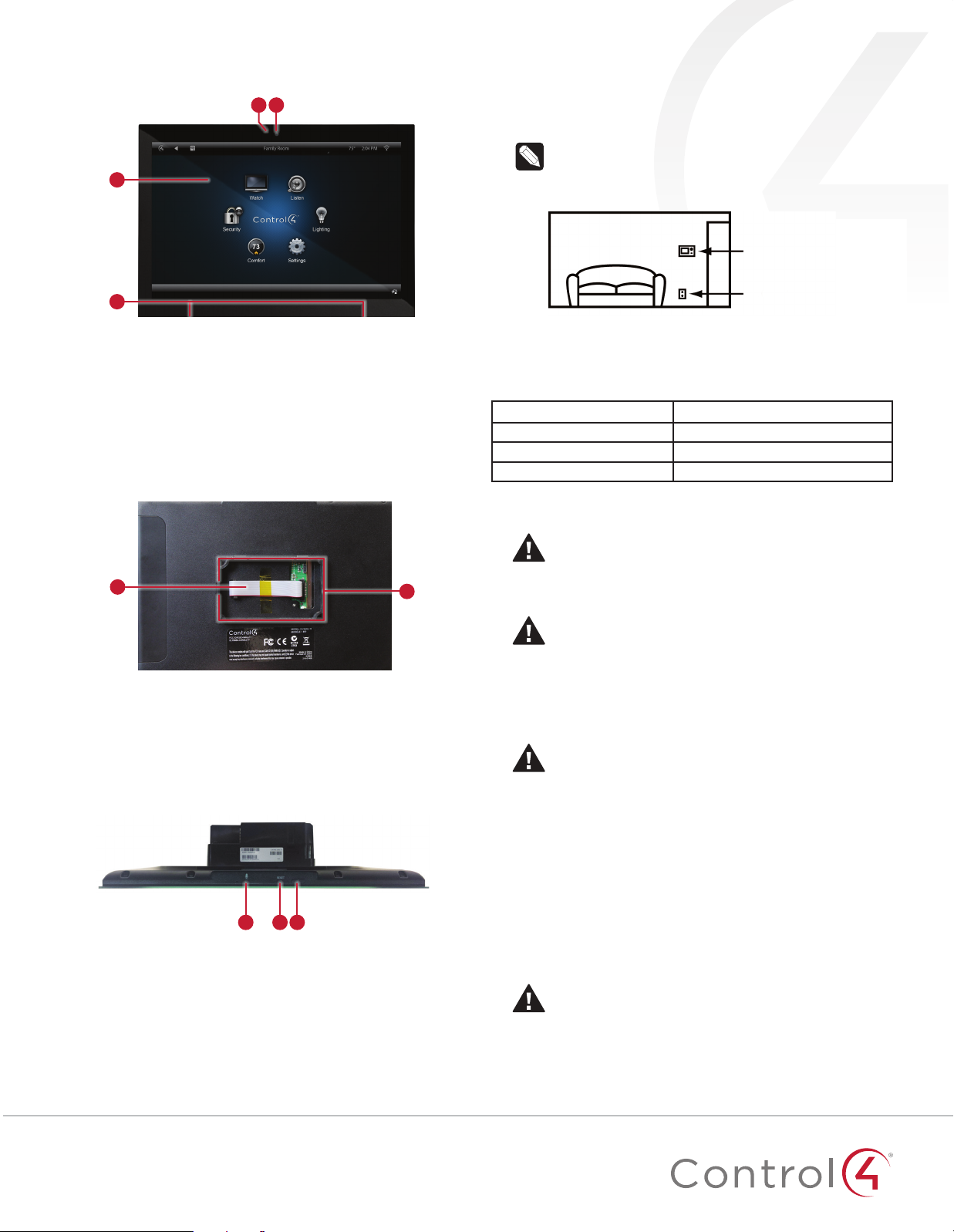
Power and network installation options
This device uses an Ethernet or WiFi network connection, and
can be powered using PoE or AC power.
Choose one of the following options to install the power and
network communication.
Caution! Do not attempt to use PoE and AC power at
the same time. Choose only one power option.
ATTENTION ! Ne pas tenter d’utiliser PoE et AC en
même temps. Choisir une seule option d’alimentation.
Page 4
Option 1: Ethernet connection with PoE
PoE supplies DC power on the Ethernet cable using a PoE
Injector (model #AC-POE1-B) or a third-party PoE solution to
provide the touch screen with power and a network connection.
The touch screen works with the Control4 PoE Injector or a thirdparty PoE Injector.
To set up your PoE and Ethernet connection with a PoE Injector:
1 Attach the PoE Injector according to the instructions in your
PoE’s installation guide if provided. Control4 PoE Injector
instructions are provided later in this document.
2 Pull the Ethernet cable from that location to where you want
to install the touch screen.
Figure 4: Ethernet with PoE—Requires Ethernet connection to PoE
injector
Option 2: Ethernet connection with AC
The Ethernet is connected directly to the switch (Figure 5). This
power connection requires both neutral and hot connections.
Figure 5: Ethernet—Requires a connection to Ethernet and AC power
Wireless Network Limitations: Many WiFi Access Points
handle Multicasts (WiFi simultaneously sent to multiple
devices, for example, when the touch screen broadcasts
video to all stations) by slowing down transmission
speed to the 1 Mb basic rate. This can cause overall WiFi
congestion in the WiFi network during the broadcast.
Video Intercom response times and images may
degrade at each device.
If a home requires a large number of WiFi Video
Intercom devices, ensure that you have a robust WiFi
network (possibly consisting of multiple access points).
Figure 6: WiFi—Requires AC Power and WAP
Power installation
Prepare the plastic power box for installation into the back box
by inserting either the Ethernet cable or the AC power cable into
the power box, and then follow the instructions.
Connecting PoE
Connect the PoE injector to power and the network, and then
connect it to the power box.
To install a Control4 PoE injector:
1 Connect the Control4 PoE injector to an AC outlet using the
power cord.
2 Connect one of the RJ-45 LAN ports on the gateway/router/
switch to the PoE Injector’s LAN port using CAT5/6 Ethernet
cable.
3 Connect the PoE Injector’s PWR LAN-OUT port to the RJ-45
Ethernet cable that will be connected to the touch screen’s
power box.
4 Pull the Ethernet cable through the top left hole of the back
box, then plug it into the Ethernet jack on the top back of
the power box (Figure 7).
Option 3: WiFi connection with AC
Place the touch screen above a power source, for example, an
outlet. Ensure that you have WiFi in the home (Figure 6).
Notes: (1) Video Intercom. Although this device
supports 802.11b/g/n, 802.11 b is not recommended for
Video Intercom use. (2) We recommend Wireless-N for
Video Intercom. See the Composer Pro User Guide for
details about the touch screen’s properties.
4
Page 5
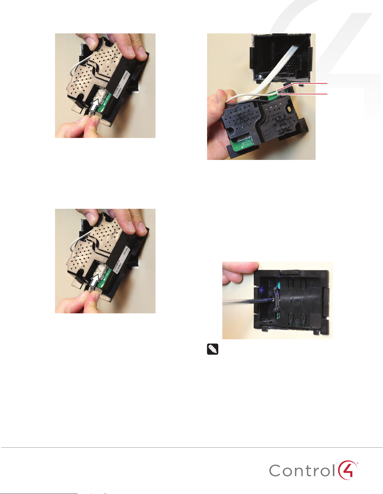
Figure 7: Insert Ethernet cable into power box
5 Go to “Attach the power box and touch screen” below.
Connecting standard Ethernet
Figure 9: Connect AC power
Neutral (N)
Line (L)
To connect to a wired network:
1 Pull the in-wall Ethernet cable through the top left hole of
the back box, then plug it into the Ethernet jack on the top
back of the power box (Figure 8).
Figure 8: Insert Ethernet cable into power box
2 Go to “Attach the power box and touch screen” below.
Connecting AC power
The steps below represent a typical U.S. installation.
1 Connect the wires to the AC power source for the touch
screen according to national and local electrical codes.
Installation may require alternative wires and the use of a
terminal block.
2 Thread the power cable through the upper back hole of the
back box to the terminal block (Figure 7).
3 Strip the black and white power wire ends to 1/4" as
necessary. Using a flat-head screwdriver, loosen the screws
on the power box’s terminal block and connect the power
wires to each terminal (Figure 9).
4 Cap the ground wire from the wall if you are using a plastic
back box. Attach the ground wire to the back box if using a
metal back box.
Attach the power box and touch screen
To attach the power box and touch screen:
1 Align and bend the wires carefully to fit them inside the back
box.
2 Align slide the power box into the back box, then secure the
power box to the back box using the two screws provided.
Figure 10: Secure power box to back box
Note: Overtightening the power box screws can warp
the box and make it dicult to attach the touch screen.
3 Straighten out the ribbon cable taped to the back of the
touch screen, then plug it into the ribbon cable port in the
power box. To make sure it’s securely connected, press it into
the port until the two locking tabs close onto the connector.
5
Page 6
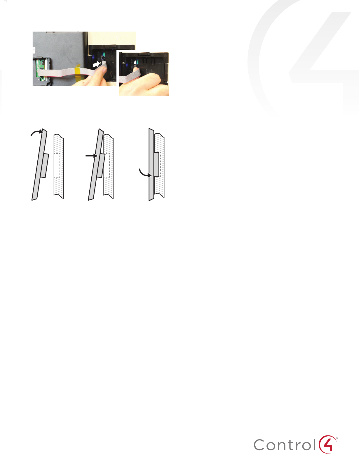
Figure 11: Attach ribbon cable to the power box
4 For easiest installation, angle the top of the touch screen
toward the wall, insert the top tabs of the mounting ring into
the power box, then press the bottom of the touch screen
into place.
Configuration
Configure the touch screen for wireless (optional)
1 After initialization, tap Network. The network configuration
page opens.
2 Under Wireless, tap Enable, then tap the network you want
to connect to.
Or, if you don’t see the network you want:
a Tap Other.
b Tap the Network Name field, type the network name with
the on-screen keyboard, then tap Done.
c Tap the Security field, then select a type of security to
use.
d Tap the Key field, type the network password with the on-
screen keyboard, then tap Done.
e Tap Connect. Notice that the IP settings change. The IP
address is set to DHCP by default.
3 (Optional) If you need to set a static IP address:
a On the Network page, tap Show advanced options, scroll
down and tap DHCP, then tap Static.
b Select each box one at a time and use the on-screen
keyboard to type the IP Address, Subnet Mask, Default
Gateway, Preferred DNS, and Alternate DNS.
c Tap Done.
4 Tap OK to return to the Network page. You can now connect
to a Director.
5 Tap OK.
Add and configure in Composer Pro
After the touch screen is installed and appears on the home
network, use Composer Pro to add it to the Control4 system and
configure it.
Use the Composer Pro System Design and Connections views to
add and configure this device.
To add and configure a T3 touch screen to a project:
1 Add the T3-T7 or T3-T10 In-Wall Touch Screen driver to your
project.
2 To configure the properties, click System Design.
3 In the project tree, select the T3 7" or T3 10" In-Wall Touch
Screen.
4 View and change the properties in the Properties pane as
needed.
Properties include:
• Network Connection—Reports the touch screen’s current
network connection type.
• Back Light—Use the arrows or type numbers to set the
light level, then click Set.
Advanced properties include:
• Enable Camera—Allows you to enable or disable the
camera.
Intercom (nested under the touch screen) properties:
• Appearance—Select to hide the touch screen from
appearing in Navigators as an available device.
• Behavior—Select the modes you want this touch screen to
support.
• Audio Control—Select the volume of individual audio
settings.
• Sip Information—Information for integrating the touch
screen into your SIP/VoIP system.
• Custom Buttons—Select to enable and label the two
available custom buttons.
• Alternate Camera—Select to use an external camera for
the video associated with the touch screen, for example, a
security camera mounted to the side of the entrance and
pointing at the door.
6
Page 7
Troubleshooting
Boot up time
When the device is booting up, it may take 30 seconds or longer
before the Green LED turns on. When it turns on, it blinks slowly
for a time and then turns o. After that, you’ll see an image on
the touch screen.
Unresponsive screen
If the camera’s LED blinks on and o for more than 30 seconds,
the device may need to be power cycled. If power cycling doesn’t
solve the problem, the touch screen may need to be restored to
factory defaults.
To power cycle the touch screen:
1 Press and hold the
until the touch screen turns o.
2 Press and release the (power) button again to turn on.
To restore to factory defaults:
1 On the touch screen’s main screen, tap Settings, System
Information, then Restore.
- OR Insert a straightened paper clip into the RESET hole on the
top of the touch screen, then press and hold it for several
seconds until the screen resets.
(power) button for several seconds
Regulatory/Safety Information
To review regulatory information for your particular Control4
products, see the information located on the Control4 website at:
ctrl4.co/reg
.
Warranty
Visit
www.control4.com/warranty
for details.
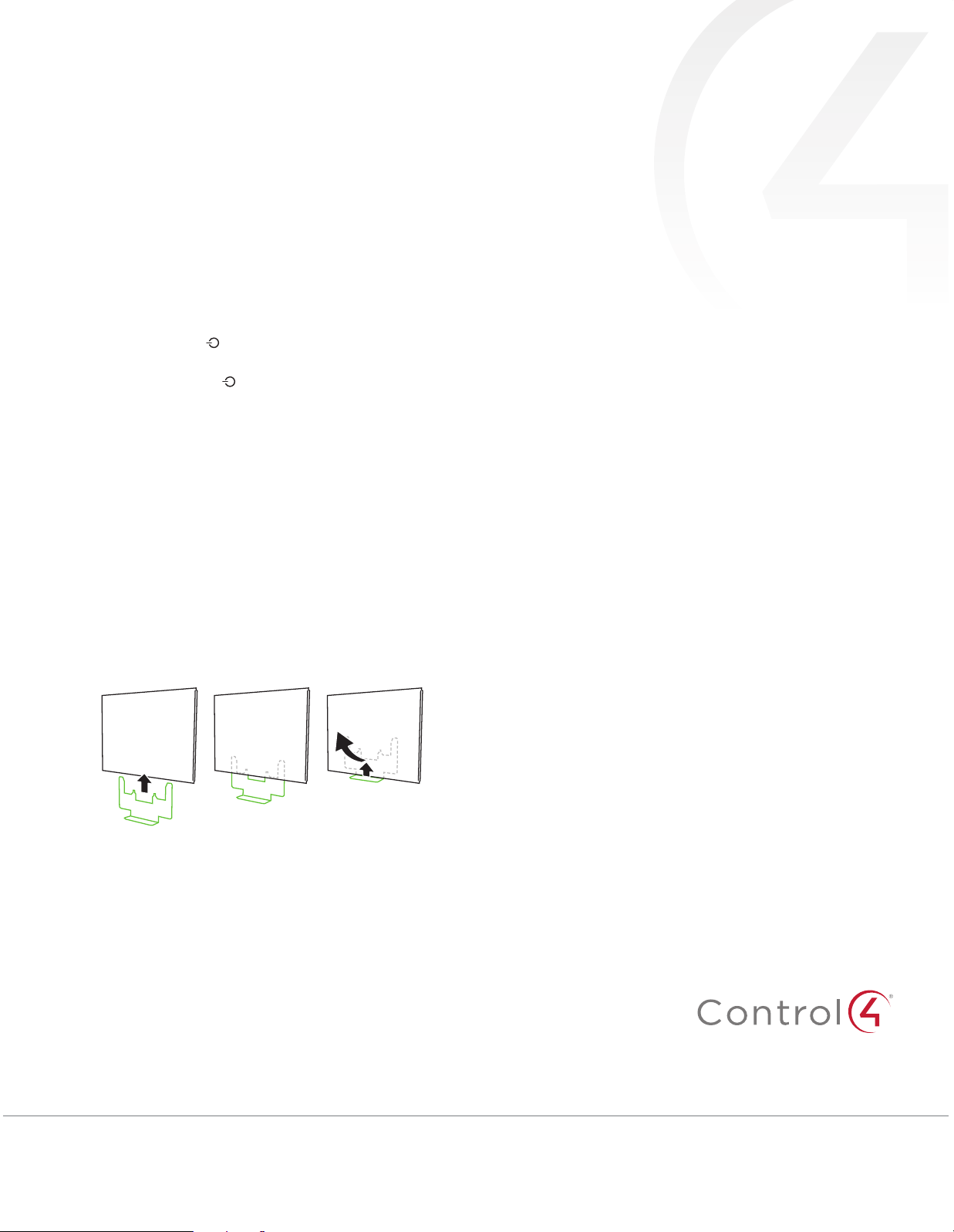
Removing the touch screen from the wall
To remove the touch screen:
1 Hold the removal tool flat against the wall, centered directly
beneath the touch screen, then slide it upward between the
wall and touch screen.
2 While pressing the tool up as far as it will go, carefully pull
the touch screen away from the wall.
Additional resources
The following resources are available for more support.
• Control4 Knowledgebase and forums
• Control4 Technical Support
• Control4 website:
• Composer documentation in online help or PDF formats,
available on the Dealer Portal under Resources
www.control4.com
control4.com | 888.400.4070
Copyright ©2015, Control4 Corporation. All rights reserved. Control4, the Control4 logo, the 4-ball logo, 4Store, 4Sight, Control My Home, Everyday Easy, and
Mockupancy are registered trademarks or trademarks of Control4 Corporation in the United States and/or other countries. All other names and brands may be claimed as
the property of their respective owners. All specifications subject to change without notice.
7
2015-03-04 MS
B
200-00387-B
Page 8

Regulatory Compliance & Safety Information for Contol4 Model C4-WALL7-XX & C4WALL10-XX.
Electrical Sa
Sécurité électrique consultatif
Im
portant Safety Information
Informations de sécurité importantes
Read the safety instructions before using this product.
Lisez les consignes de sécurité avant d'utiliser ce produit.
1.
1.
2.
2.
3.
fety Advisory
Read these instructions
z ces instructions.
Lise
Keep these instructions
Con
servez ces instructions.
Heed all warnings.
.
.
3. Respectez tous les avertissements.
4. Follow all inst
Suivez toutes les inst
4.
5.
Do not use this apparatus near wate
ructions.
ructions.
r.
5. Ne pas utiliser cet appareil près de l'eau.
6.
Clean only wi
6.
Nettoyez-le uniquement avec un chiffon se
7.
Do not block any ventilation openings. Install in accordance with the manufac
inst
ructions.
7.
Ne pas bloquer les ouvertures de ventilation. Installer conformément aux instructions du
fabricant.
8.
Do not install near any heat sources such as radiators, heat registers, stoves, or
ratus (including amplifiers) that produce heat.
appa
Ne pas installer près de sources de chaleur telles que des radiateurs, registres de
8.
chaleur, poêles, ou autres appareils (incluant les amplificateurs) qui produise
chal
eur.
9.
Do not defeat the safety purpose of the polarized or grounding-type plug. A polariz
plug ha
and a third g
If the provided plug do
the obsolete outlet.
9.
Ne pas contourner le dispositif de sécurité de la fiche polarisée ou de mise à la te
fiche pol
th dry cloth.
c.
turer’s
nt de la
s two blades with one wider than the other. A grounding type plug has two blade
rounding prong. The wide blade or the third prong is provided for yo
es not fit into your outlet, consult an electrician for replacem
arisée possède deux lames dont une plus large que l'autre. Une fiche de
other
ed
s
ur safety.
ent of
rre. Une
terre a
Page 9

deux lames et une troisième broche de terre. La lame large ou la troisième broche est
fournie pour votre sécurité. Si la fiche fournie ne s'adapte pas à votre prise, consultez un
électricien pour le remplacement de la prise obsolète.
10. Protect the power cord from being walked on or pinched particularly at plugs,
convenience receptacles, and the point where they exit from the apparatus.
10. Protégez le cordon d'alimentation ne soit piétiné ou pincé, en particulier au niveau des
fiches, des prises et au point où il sort de l'appareil.
11. Only use attachments/accessories specified by the manufacturer.
11. Utilisez uniquement des fixations / accessoires spécifiés par le fabricant.
12. Use only with the cart, stand, tripod, bracket, or table specified by the manufacturer, or
sold with the apparatus. When a cart is used, use caution when moving the
cart/apparatus combination to avoid injury from tip-over.
12. Utilisez uniquement avec le chariot, le socle, le trépied, le support ou la table spécifiés
par le fabricant ou vendu avec l'appareil. Lorsque vous utilisez un chariot, soyez prudent
lorsque vous déplacez l'ensemble chariot / appareil pour éviter des blessures dues au
renversement.
13. Unplug this apparatus during lightning storms or when unused for long periods of time.
This equipment uses AC power which can be subjected to electrical surges, typically
lightning transients which are very destructive to customer terminal equipment connected
to AC power sources. The warranty for this equipment does not cover damage caused
by electrical surge or lightning transients. To reduce the risk of this equipment becoming
damaged it is suggested that the customer consider installing a surge arrestor.
13. Débranchez cet appareil pendant les orages ou lorsqu'il n'est pas utilisé pendant de
longues périodes de temps. Cet équipement utilise la puissance AC qui peuvent être
soumis à des surtensions électriques, la foudre généralement transitoires qui sont très
destructives envers les équipements terminaux connectés à des sources d'alimentation
CA. La garantie de cet appareil ne couvre pas les dommages causés par les surtensions
électriques ou transitoires de foudre. Pour réduire le risque de cet équipement devient
endommagé, il est suggéré que le client envisager l'installation d'un limiteur de
surtension.
14. Refer all servicing to qualified service personnel. Servicing is required when the
apparatus has been damaged in any way, such as power-supply cord or plug is
damaged, liquid has been spilled or objects have fallen into the apparatus, the apparatus
has been exposed to rain or moisture, does not operate normally, or has been dropped.
14. Confiez toutes les réparations à un personnel qualifié. Une réparation est nécessaire
lorsque l'appareil a été endommagé de quelque façon que ce soit le cordon
d'alimentation ou la fiche est endommagé, du liquide a été renversé ou si des objets sont
tombés dans l'appareil, l'appareil a été exposé à la pluie ou à l'humidité, ne fonctionne
pas normalement , ou s'il est tombé.
15. Use the circuit breaker to disconnect the apparatus from the AC mains. The circuit
breaker shall remain readily accessible.
15. Utiliser le disjoncteur pour déconnecter l'appareil de l'alimentation secteur. Le disjoncteur
doit rester facilement accessible.
16. To completely disconnect unit power from the AC mains, turn off the circuit breaker. To
reconnect power, turn on the circuit breaker following all safety instructions and
guidelines.
Page 10
16. Pour couper entièrement l'alimentation appareil de l'alimentation secteur, éteignez le
disjoncteur. Pour rétablir le courant, mettez le disjoncteur après les consig nes de sécurité
et des lignes directrices.
17. This product relies on the buildings installation for short-circuit (overcurrent) protection.
Ensure that the protective device is rated not greater than: 20A.
17. Ce produit repose sur l'installation des bâtiments pour les courts-circuits (surintensité) de
protection. Assurez-vous que le dispositif de protection est assignée ne dépassant pas:
20A.
18. CAUTION: As with all batteries, there is a risk of explosion or personal injury if the
battery is replaced by an incorrect type. Dispose of used battery according to the
instructions of the battery manufacturer and applicable environmental guidelines. Do not
open, puncture or incinerate the battery, or expose it to conducting materials, moisture,
liquid, fire or heat above 54° C or 130° F.
18. ATTENTION: Comme avec toutes les batteries, il ya un risque d'explosion ou de blessure
si la batterie est remplacée par un type incorrect. Éliminez les batteries usagées selon
les instructions du fabricant de la batterie et applicables des directives
environnementales. Ne pas ouvrir, percer ou incinérer la batterie, ou de l'exposer à des
matériaux conducteurs, de l'humidité, du liquide, un incendie ou une température
supérieure à 54 ° C ou 130 ° F.
19. Never push objects of any kind into this product through cabinet slots as they may touch
dangerous voltage points or short out parts that could result in fire or electric shock.
19. N'introduisez jamais d'objets d'aucune sorte dans ce produit à travers les fentes du
boîtier car ils pourraient toucher des points de tension dangereux ou court-circuiter des
pièces qui pourraient entraîner un incendie ou un choc électrique.
20. This product can interfere with electrical equipment such as tape recorders, TV sets,
radios, computers and microwave ovens if placed in close proximity.
20. Ce produit peut interférer avec des appareils électriques tels que les magnétophones,
téléviseurs, radios, ordinateurs et fours à micro-ondes si placés à proximité.
The lightning flash and arrow head within the triangle is a warning sign alerting
you of dangerous voltage inside the product
L'éclair et la flèche dans le triangle est un signe d'alerte pour vous avertir d'une
tension dangereuse à l'intérieur du produit
Caution: To reduce the risk of electric shock, do not remove cover (or back). No
user serviceable parts inside. Refer servicing to qualified service personnel.
Attention: Pour réduire le risque de choc électrique, ne pas retirer le couvercle
(ou l'arrière). Aucune pièce réparable par l'utilisateur. Confiez l'entretien à un
personnel qualifié.
The exclamation point within the triangle is a warning sign alerting you of
important instructions accompanying the product.
Le point d'exclamation dans un triangle est un signe d'avertissement vous
signale des instructions importantes accompagnant le produit.
See marking on bottom / back of product
Voir le marquage sur les bas / dos du produit
Page 11
Warning!: To reduce the risk of electrical shock, do not expose this
apparatus to rain or moisture
AVERTISSEMENT! Pour réduire le risque de choc électrique,
n'exposez pas cet appareil à la pluie ou à l'humidité.
Save these instructions
Conservez ces instructions
Compliance of this equipment is confirmed by the following label that is placed on the equipment:
Conformité de cet appareil est confirmé par le symbole suivant qui est placé sur l'équipement:
USA & Canada Compliance
FCC Part 15, Subpart B Unintentional Emissions Interference Statement
This equipment has been tested and found to comply with the limits for a Class B digital device,
pursuant to Part 15 of the FCC rules. These limits are designed to provide reasonable protection
against harmful interference when the equipment is operated in a residential installation. This
equipment generates uses and can radiate radio frequency energy and, if not installed and used
in accordance with the instructions, may cause harmful interference to radio communications.
However, there is no guarantee that interference will not occur in a particular installation. If this
equipment does cause harmful interference to radio or television reception, which can be
determined by turning the equipment off and on, the user is encouraged to try to correct the
interference by one or more of the following measures:
Reorient or relocate the receiving antenna.
Increase the separation between the equipment and receiver.
Connect the equipment into an outlet on a circuit different from that to which the receiver
is connected.
Consult the dealer or an experienced radio/TV technician for help.
FCC Partie 15, sous-section B Unintentional Déclaration sur les interférences des
émissions
Cet équipement a été testé et jugé conforme aux limites établies pour un dispositif numérique de
classe B, conformément à la Partie 15 des règlements de la FCC. Ces limites sont conçues pour
fournir une protection raisonnable contre les interférences nuisibles lorsque l'équipement est
utilisé dans une installation résidentielle. Cet équipement génère, utilise et peut émettre de
l'énergie rayonnent fréquence et, s'il n'est pas installé et utilisé conformément aux instructions, il
peut causer des interférences nuisibles aux communications radio. Cependant, il n'existe aucune
garantie que des interférences ne se produiront pas dans une installation parti culière. Si cet
équipement provoque des interférences nuisibles à la réception radio ou télévision, ce qui pe ut
Page 12

être déterminé en mettant l'équipement hors et sous tension, l'utilisateur est encouragé à essayer
de corriger l'interférence par une ou plusieurs des mesures suivantes:
Réorienter ou déplacer l'antenne de réception.
Augmenter la distance entre l'équipement et le récepteur.
Connecter l'équipement à une prise sur un circuit différent de celui sur lequel le récepteur
est branché.
Consulter le revendeur ou un technicien radio / télévision qualifié pour obtenir de l'aide.
This device complies with part 15 of the FCC rules and Industry Canada’s licence-exempt RSSGEN. Operation is subject to the following two conditions: (1) This device may not cause harmful
interference, and (2) this device must accept any interference received, including interference that
may cause undesired operation.
Le présent appareil est conforme partie 15 des règles de la FCC et aux RSS-GEN d'Industrie
Canada applicables aux appareils radio exempts de licence. L'exploitation est autorisée aux deux
conditions suivantes : (1) l'appareil ne doit pas produire de brouillage, et (2) l'utilisateur de
l'appareil doit accepter tout brouillage radioélectrique subi, même si le brouillage est susceptible
d'en compromettre le fonctionnement.
IMPORTANT! Any changes or modifications not expressly approved by the party responsible for
compliance could void the user’s authority to operate this equipment.
IMPORTANT! Tous les changements ou modifications pas expressément approuvés par la partie
responsable de la conformité ont pu vider l’autorité de l’utilisateur pour actionner cet équipement.
FCC Part 15, Subpart C / RSS-210 Intentional Emissions Interference Statement
Compliance of this equipment is confirmed by the following certification numbers that are placed
on the equipment:
Notice: The term “FCC ID:” and “IC:” before the certification number signifies that FCC and
Industry Canada technical specifications were met. The FCC ID: and IC: numbers listed below
are for the WiFi module that was certified as a Limited Modular Approval.
FCC ID: R33C4LGWM
IC: 7848A-C4LGWM
The end user equipment that contains the certified WiFi module are labeled with the following on
the outside of the equipment:
Contains FCC ID: R33C4LGWM
Contains IC: 7848A-C4LGWM
This equipment must be installed by qualified professionals or contractors in accordance with
FCC Part 15.203 & IC RSS-210, Antenna Requirements. Do not use any antenna other than the
one provided with the unit.
FCC Partie 15, sous-partie C / RSS-210 Déclaration volontaire des émissions interféren ces
Conformité de cet appareil est confirmé par les chiffres de certification suivants qui sont placés
sur l'équipement:
Avis: Le terme «FCC ID:" et "IC:" devant le numéro de certification signifie que les spécifications
techniques de la FCC et d'Industrie Canada ont été respectées. La FCC ID: et IC: numé ros
Page 13

indiqués ci-dessous sont pour le module WiFi qui a été certifiée en tant que Approbation limitée
modulaire.
FCC ID: R33C4LGWM
IC: 7848A-C4LGWM
L'équipement d'utilisateur final qui contient le module WiFi certifiée sont marqués par le suivant à
l'extérieur de l'objet:
Contient ID FCC: R33C4LGWM
Contient IC: 7848A-C4LGWM
Cet équipement doit être installé par des professionnels qualifiés ou entrepreneurs conformément
aux normes FCC partie 15.203 & IC RSS-210, Exigences d'antenne. Ne pas utiliser une antenne
autre que celui fourni avec l'appareil.
RF Radiation Exposure Statement
This equipment complies with the FCC/IC radiation exposure limits set fourth for portable
transmitting devices operation in an uncontrolled environment. End users must follow the specific
operating instructions to satisfy RF exposure compliance.
The equipment should only be used or installed at locations where there is normally
greater than a 20cm separation between the antenna and all persons.
This transmitter must not be co-located or operation in conjunction with any other
antenna or transmitter.
Any changes or modifications not expressly approved by the party responsible for
compliance could void the user’s authority to operate this equipment.
Déclaration d'exposition aux radiations RF
Cet équipement est conforme aux limites FCC / IC d'exposition aux rayonnements définies
quatrième opération appareils portables transmettre dans un environnement non contrôlé. Les
utilisateurs finaux doivent suivre les instructions de fonctionnement spécifiques pour satisfaire la
conformité aux expositions RF.
L'équipement ne doit être utilisé ou installé à des endroits où il est normalement
supérieure à une séparation de 20 cm entre l'antenne et toute personne.
Cet émetteur ne doit pas être co-localisés ou fonctionnement en conjonction avec une
autre antenne ou un autre émetteur.
Tout changement ou modification non expressément approuvé par la partie responsable
de la conformité pourraient annuler l'autorité de l'utilisateur à utiliser cet équipement.
Page 14

European Compliance
Conformity of the equipment with the guidelines below is attested by the application of the CE
mark.
CE Declaration of Conformity
Manufacturer’s Name: CONTROL4 CORPORATION
Manufacturer’s Address: 11734 S. ELECTION ROAD SUITE 200
SALT LAKE CITY
UT 84020 USA
EU Representative Name: CONTROL4 EMEA LIMITED
EU Representative Address: UNIT3, GREEN PARK BUSINESS CENTRE
SULTON-ON-THE FOREST
YORK YO61 IET, UNITED KINGDOM
Product Name(s): In-Wall Touch Screen
Brand: Contol4
Model(s): C4-WALL7-XX & C4-WALL10-XX
Product Standard(s) to which Conformity of the Council Directive(s) is declared:
EMC - 2004/108/EC “Electromagnetic Compatibility (EMC) Directive”:
(Emissions) EN 55022:2010, (Immunity) EN 55024:2010, EN 301 489-1 V1.9.2 (2011-09), EN
301 489-17 V2.2.1 (2012-09), EN 61000-3-2:2006 + A1:2009 + A2:2009 & EN 61000-3-3:2008
Safety – 206/95/EC “Low Voltage Directive (LVD)”:
EN 60950-1:2006/A11:2009/A1:2010/A12:2011
Telecom & Radio - 1999/5/EC Radio equipment and Telecommunications Terminal
Equipment (R&TTE) Directive:
EN 300 328 V1.8.1
RoHS - 2011/65/EU Restriction of the Use of certain Hazardous Substances in Electrical
and Electronic Equipment (EEE) & WEEE - 2002/96/EC Waste of Electrical and Electronic
Equipment (EEE).
We, the undersigned, hereby declare that the equipment specified above conforms to the above
directives and standards. Date of Issue: March 10, 2015
Legal Representative
Signature
Roger Midgley
Sr. Regulatory Compliance Engineer
Page 15
Recycling
Control4 understands that a commitment to the environment is essential for a health life and
sustainable growth for future generations. We are committed to supporting the environmental
standards, laws, and directives that have been put in place by various communities and countries
that deal with concerns for the environment. This commitment is represented by combining
technological innovation with sound environmental business decisions.
WEEE Compliance
Control4 is committed to meeting all requirements of the Waste Electrical and Electronic
Equipment (WEEE) directive (2002/96/EC). The WEEE directive requires the manufacturers of
electrical and electronic equipment who sell in EU countries: (1) label their equipment to notify
customers that it needs to be recycled, and (2) provide a way for their products to be
appropriately disposed of or recycled at the end of their product lifespan. For collection or
recycling of Control4 products, please contact your local Control4 representative or dealer.
About this Document
Copyright © 2015 Control4 Corporation. All rights reserved. Control4 and the Control4 logo are
registered trademarks or trademarks of Control4 Corporation in the United States and/or other countries.
Part Number 200-00? Rev A, 3/10/2015
Page 16

Regulatory Compliance & Safety Information for Contol4 Model C4-WALL7-XX & C4WALL10-XX.
Electrical Safety Advisory
Sécurité électrique consultatif
Important Safety Information
Informations de sécurité importantes
Read the safety instructions before using this product.
Lisez les consignes de sécurité avant d'utiliser ce produit.
1. Read these instructions.
1. Lisez ces instructions.
2. Keep these instructions.
2. Conservez ces instructions.
3. Heed all warnings.
3. Respectez tous les avertissements.
4. Follow all instructions.
4. Suivez toutes les instructions.
5. Do not use this apparatus near water.
5. Ne pas utiliser cet appareil près de l'eau.
6. Clean only with dry cloth.
6. Nettoyez-le uniquement avec un chiffon sec.
7. Do not block any ventilation openings. Install in accordance with the manufacturer’s
instructions.
7. Ne pas bloquer les ouvertures de ventilation. Installer conformément aux instructions du
fabricant.
8. Do not install near any heat sources such as radiators, heat registers, stoves, or other
apparatus (including amplifiers) that produce heat.
8. Ne pas installer près de sources de chaleur telles que des radiateurs, registres de
chaleur, poêles, ou autres appareils (incluant les amplificateurs) qui produisent de la
chaleur.
9. Do not defeat the safety purpose of the polarized or grounding-type plug. A polarized
plug has two blades with one wider than the other. A grounding type plug has two blades
and a third grounding prong. The wide blade or the third prong is provided for your safety.
If the provided plug does not fit into your outlet, consult an electrician for replacement of
the obsolete outlet.
9. Ne pas contourner le dispositif de sécurité de la fiche polarisée ou de mise à la terre. Une
fiche polarisée possède deux lames dont une plus large que l'autre. Une fiche de terre a
Page 17

deux lames et une troisième broche de terre. La lame large ou la troisième broche est
fournie pour votre sécurité. Si la fiche fournie ne s'adapte pas à votre prise, consultez un
électricien pour le remplacement de la prise obsolète.
10. Protect the power cord from being walked on or pinched particularly at plugs,
convenience receptacles, and the point where they exit from the apparatus.
10. Protégez le cordon d'alimentation ne soit piétiné ou pincé, en particulier au niveau des
fiches, des prises et au point où il sort de l'appareil.
11. Only use attachments/accessories specified by the manufacturer.
11. Utilisez uniquement des fixations / accessoires spécifiés par le fabricant.
12. Use only with the cart, stand, tripod, bracket, or table specified by the manufacturer, or
sold with the apparatus. When a cart is used, use caution when moving the
cart/apparatus combination to avoid injury from tip-over.
12. Utilisez uniquement avec le chariot, le socle, le trépied, le support ou la table spécifiés
par le fabricant ou vendu avec l'appareil. Lorsque vous utilisez un chariot, soyez prudent
lorsque vous déplacez l'ensemble chariot / appareil pour éviter des blessures dues au
renversement.
13. Unplug this apparatus during lightning storms or when unused for long periods of time.
This equipment uses AC power which can be subjected to electrical surges, typically
lightning transients which are very destructive to customer terminal equipment connected
to AC power sources. The warranty for this equipment does not cover damage caused
by electrical surge or lightning transients. To reduce the risk of this equipment becoming
damaged it is suggested that the customer consider installing a surge arrestor.
13. Débranchez cet appareil pendant les orages ou lorsqu'il n'est pas utilisé pend ant d e
longues périodes de temps. Cet équipement utilise la puissance AC qui peuvent être
soumis à des surtensions électriques, la foudre généralement transitoires qui sont très
destructives envers les équipements terminaux connectés à des sources d'alimentation
CA. La garantie de cet appareil ne couvre pas les dommages causés par les surtensions
électriques ou transitoires de foudre. Pour réduire le risque de cet équipement devient
endommagé, il est suggéré que le client envisager l'installation d'un limiteur de
surtension.
14. Refer all servicing to qualified service personnel. Servicing is required when the
apparatus has been damaged in any way, such as power-supply cord or plug is
damaged, liquid has been spilled or objects have fallen into the apparatus, the apparatus
has been exposed to rain or moisture, does not operate normally, or has been dropped.
14. Confiez toutes les réparations à un personnel qualifié. Une réparation est nécessaire
lorsque l'appareil a été endommagé de quelque façon que ce soit le cordon
d'alimentation ou la fiche est endommagé, du liquide a été renversé ou si des objets sont
tombés dans l'appareil, l'appareil a été exposé à la pluie ou à l'humidité, ne fonctionne
pas normalement , ou s'il est tombé.
15. Use the circuit breaker to disconnect the apparatus from the AC mains. The circuit
breaker shall remain readily accessible.
15. Utiliser le disjoncteur pour déconn ec ter l'appareil de l'alimentation secteur. Le disjoncteur
doit rester facilement accessible.
16. To completely disconnect unit power from the AC mains, turn off the circuit breaker. To
reconnect power, turn on the circuit breaker following all safety instructions and
guidelines.
Page 18

Caution: To reduce the risk of electric shock, do not remove cover (or back). No
The exclamation point within the triangle is a warning sign alerting you of
signale des instructions importantes accompagnant le produit.
Voir le marquage sur les bas / dos du produit
16. Pour couper entièrement l'alimentation appareil de l'alimentation secteur, éteignez le
disjoncteur. Pour rétablir le courant, mettez le disjoncteur après les consignes de sécurité
et des lignes directrices.
17. This product relies on the buildings installation for short-circuit (overcurrent) protection.
Ensure that the protective device is rated not greater than: 20A.
17. Ce produit repose sur l'installation des bâtiments pour les courts-circuits (surintensité) de
protection. Assurez-vous que le dispositif de protection est assignée ne dépassant pas:
20A.
18. CAUTION: As with all batteries, there is a risk of explosion or personal injury if the
battery is replaced by an incorrect type. Dispose of used battery according to the
instructions of the battery manufacturer and applicable environmental guidelines. Do not
open, puncture or incinerate the battery, or expose it to conducting materials, moisture,
liquid, fire or heat above 54° C or 130° F.
18. ATTENTION: Comme avec toutes les batteries, il ya un risque d'explosion ou de blessure
si la batterie est remplacée par un type incorrect. Éliminez les batteries usagées selon
les instructions du fabricant de la batterie et applicables des directives
environnementales. Ne pas ouvrir, percer ou incinérer la batterie, ou de l'exposer à des
matériaux conducteurs, de l'humidité, du liquide, un incendie ou une température
supérieure à 54 ° C ou 130 ° F.
19. Never push objects of any kind into this product through cabinet slots as they may touch
dangerous voltage points or short out parts that could result in fire or electric shock.
19. N'introduisez jamais d'objets d'aucune sorte dans ce produit à travers les fentes du
boîtier car ils pourraient toucher des points de tension dangereux ou court-circuiter des
pièces qui pourraient entraîner un incendie ou un choc électrique.
20. This product can interfere with electrical equipment such as tape recorders, TV sets,
radios, computers and microwave ovens if placed in close proximity.
20. Ce produit peut interférer avec des appareils électriques tels que les magnétophones,
téléviseurs, radios, ordinateurs et fours à micro-ondes si placés à proximité.
The lightning flash and arrow head within the triangle is a warning sign alerting
you of dangerous voltage inside the prod uc t
L'éclair et la flèche dans le triangle est un signe d'alerte pour vous avertir d'une
tension dangereuse à l'intérieur du produit
user serviceable parts inside. Refer servicing to qualified service personnel.
Attention: Pour réduire le risque de choc électrique, ne pas retirer le couvercle
(ou l'arrière). Aucune pièce réparable par l'utilisateur. Confiez l'entretien à un
personnel qualifié.
important instructions accompanying the product.
Le point d'exclamation dans un triangle est un signe d'avertissement vous
See marking on bottom / back of product
Page 19

apparatus to rain or moisture
AVERTISSEMENT! Pour réduire le risque de choc électrique,
Warning!: To reduce the risk of electrical shock, do not expose this
n'exposez pas cet appareil à la pluie ou à l'humidité.
Save these instructions
Conservez ces instructions
Compliance of this equipment is confirmed by the following label that is placed on the equipment:
Conformité de cet appareil est confirmé par le symbole suivant qui est placé sur l'équipem ent:
USA & Canada Compliance
FCC Part 15, Subpart B Unintentional Emissions Interference Statement
This equipment has been tested and found to comply with the limits for a Class B digital device,
pursuant to Part 15 of the FCC rules. These limits are designed to provide reasonable protection
against harmful interference when the equipment is operated in a residential installation. This
equipment generates uses and can radiate radio frequency energy and, if not installed and used
in accordance with the instructions, may cause harmful interference to radio communications.
However, there is no guarantee that interference will not occur in a particular installation. If this
equipment does cause harmful interference to radio or television reception, which can be
determined by turning the equipment off and on, the user is encouraged to try to correct the
interference by one or more of the following measures:
• Reorient or relocate the receiving antenna.
• Increase the separation between the equipment and receiver.
• Connect the equipment into an outlet on a circuit different from that to which the receiver
is connected.
• Consult the dealer or an experienced radio/TV technician for help.
FCC Partie 15, sous-section B Unintentional Déclaration sur les interférences des
émissions
Cet équipement a été testé et jugé conforme aux limites établies pour un dispositif numérique de
classe B, conformément à la Partie 15 des règlements de la FCC. Ces limites sont conçues pour
fournir une protection raisonnable contre les interférences nuisibles lorsque l'équipement est
utilisé dans une installation résidentielle. Cet équipement génère, utilise et peut émettre de
l'énergie rayonnent fréquence et, s'il n'est pas installé et utilisé conformément aux instructions, il
peut causer des interférences nuisibles aux communications radio. Cependant, il n'existe aucune
garantie que des interférences ne se produiront pas dans une installation particulière. Si cet
équipement provoque des interférences nuisibles à la réception radio ou télévision, ce qui peut
Page 20

être déterminé en mettant l'équipement hors et sous tension, l'utilisateur est encouragé à essayer
de corriger l'interférence par une ou plusieurs des mesures suivantes:
éorienter ou déplacer l'antenne de réception.
• R
• Augmenter la distance entre l'équipement et le récepteur.
• C
onnecter l'équipement à une prise sur un c irc uit dif f érent de celui sur lequel le récepteur
est branché.
onsulter le revendeur ou un technicien radio / télévision qualifié pour obtenir de l'aide.
• C
This device complies with part 15 of the FCC rules and Industry Ca nad a’s licenc e-exempt RSSGEN. Operation is subject to the following two conditions: (1) This device may not cause harmful
interference, and (2) this device must accept any interference received, including interference that
may cause undes ired operation.
Le présent appare il est conforme partie 15 des règ les de la FCC et aux RSS-GEN d'Industrie
Canada applicables aux a p par eils radio exempts de licence. L'exploitation est autor is ée aux de ux
conditions suivantes : (1) l'appareil ne doit pas produire de brouillage, et (2) l'utilisateur de
l'appareil doit accepter tout brouillage radio électrique subi, m ême si le brouillage est sus ceptible
d'en compromettre le fonctionnement.
IMPORTANT! Any changes or modifications not expressly approved by the party responsible f or
compliance could void the user’s
IMPORTANT! Tous les changements ou modifications pas expressément approuvés par la partie
responsable de la conformité ont pu vider l’autorité de l’utilisateur pour actionner cet équipement.
authority to operate this equipment.
FCC Part 15, Subpart C / RSS-210 Intentional Emissions Interference Statement
Compliance of this equipment is c onfirmed by the following certification numbers that are placed
on the equipment:
Notice: The term “FCC ID:” and “IC:” before the certification number signifies that FCC and
Industry Canada technical specifications were met. The FCC ID: and IC: numbers listed below
are for the WiFi module.
FCC ID: R33C4WALL5G
IC: 7848A-C4LGWM
This equipment must be installed by qualified professionals or contractors in accordance with FCC
Part 15.203 & IC RSS-210, Antenna Requirements. Do not use any antenna other than the one
provided with the unit.
FCC Partie 15, sous-partie C / RSS-210 Déclaration volontaire des émissions interférences
Conformité de cet appareil est confirmé par les chiffres de certification suivants qui sont placés
sur l'équipement:
Avis: Le terme «FCC ID:" et "IC:" devant le numéro de certification signifie que les spécifications
techniques de la FCC et d'Industrie Canada ont été respectées. La FCC ID: et IC: numéros
Page 21

indiqués ci-dessous sont pour le module WiFi qui a été certifiée en tant que Approbation limitée
modulaire.
FCC ID: R33C4WALL5G
IC: 7848A-C4LGWM
Cet équipement doit être installé par des professionnels qualifiés ou entrepreneurs conformément
aux normes FCC partie 15.203 & IC RSS-210, Exigences d'antenne. Ne pas utiliser une antenne
autre que celui fourni avec l'appareil.
RF Radiation Exposure Statement
This equipment complies with the FCC/IC radiation exposure limits set fourth for portable
transmitting devices operation in an uncontrolled environment. End users must follow the specific
operating instructions to satisfy RF exposure compliance.
he equipment should only be used or installed at locations where there is normally
• T
greater than a 20cm separation between the antenna and all persons.
• This transmitter must not be co-located or operation in conjunc tio n with any other
antenna or transmitter.
• Any changes or modifications not expressly approved by the party responsible for
compliance could void the user’s authority to operate this equipment.
D
éclaration d'exposition aux radiations RF
Cet équipement est conforme aux limites FCC / IC d'exposition aux rayonnements définies
quatrième opération appareils portables transmettre dans un environnem ent non c ontrôlé . Les
utilisateurs finaux doivent suivre les instructions de fonctionnement spécifiques pour satisfaire la
conformité aux expositions RF.
• L'
équipement ne doit être utilisé ou installé à des endroits où il est normalement
supérieure à une séparation de 20 cm entre l'antenne et toute personne.
• Cet émetteur ne doit pas être co-localisés ou fonctionnement en conjonction avec
re antenne ou un autre ém et teur.
aut
• Tout changement ou modification non expressément approuvé par la partie responsable
de la conformité pourraient annuler l'autorit é de l'utilisateur à utiliser cet équipement.
une
Page 22

European Compliance
Conformity of the equipment with the guidelines below is attested by the application of the CE
mark.
C
E Declaration of Conformity
Manuf
acturer’s Name: CONTROL4 CORPORATION
Manufacturer’s Address: 11734 S. ELECTION ROAD SUITE 200
SALT LAKE CITY
UT 84020 USA
E
U Representative Name: CONTROL4 EMEA LIMITED
EU Representative Address: UNIT3, GREEN PARK BUSINESS CENTRE
SULTON-ON-THE FOREST
YORK YO61 IET, UNITED KINGDOM
P
roduct Name(s): In-Wall Touch Screen
Brand: Contol4
Model(s): C4-WALL7-XX & C4-WALL10-XX
roduct Standard(s) to which Conformity of the Council Directive(s) is declared:
P
EM
C - 2004/108/EC “Electromagnetic Compatibility (EMC) Directive”:
(Emissions) EN 5 5032:2012, (Immunity) EN 55024:2010, EN 301 489-1 V1.9.2 (2011-09), EN
301 489-17 V2.2.1 (2012-09), EN 61000-3-2:2006 + A1:2009 + A2:2009 & EN 61000-3-3:2008
afety – 206/95/EC “Low Voltage Directive (LVD)”:
S
EN 60950-1:2006/A11:2009/A1:2010/A12:2011
T
elecom & Radio - 1999/5/EC Radio equipment and Telecommunications Terminal
Equipment (R&TTE) Directive:
EN 300 328 V2.1.1 & EN 301 893 V2.1.1
RoHS - 2011/65/EU Restriction of the Use of certain Hazardous Substances in Electrical
and Electronic Equipment (EEE) & WEEE - 2002/96/EC Waste of Electrical and El ectronic
Equipment (EEE).
e, the undersigned, here by declare that th e equipment s pecified abo ve conforms to the above
W
directives and standards. Date of Issue: Apr il 23, 201 8
Legal Representative
Signature
R
oger Midgley
Sr. Regulatory Compliance Engineer
Page 23

Recycling
Control4 understands that a commitment to the environment is essential for a health life and
sustainable growth for future generations. We are committed to supporting the environmental
standards, laws, and directives that have been put in place by various communities and countries
that deal with concerns for the environment. This commitment is represented by combining
technological innovation with sound environmental business decisions.
WEEE Compliance
Control4 is committed to meeting all requirements of the Waste Electrical and Electronic
Equipment (WEEE) directive (2002/96/EC). The WEEE directive requires the manufacturers of
electrical and electronic equipment who sell in EU countries: (1) label their equipment to notify
customers that it needs to be recycled, and (2) provide a way for their products to be
appropriately disposed of or recycled at the end of their product lifespan. For collection or
recycling of Control4 products, please contact your local Control4 representative or dealer.
About this Document
Copyright © 2018 Control4 Corporation. All rights reserved. Control4 and the Control4 logo are
registered trademarks or trademarks of Control4 Corporation in the United States and/or other countries.
Part Number 200-00414 Rev A, 4/23/2018
 Loading...