

Page 1
Home Controller HC-200
Installation Guide
Supported Model
C4-HC200-E-B Home Controller HC-200
Introduction to Home Controller HC-200
The Control4 Home Controller HC-200 provides options for controlling lights,
home theaters, distributed audio systems, and other devices controlled using
various protocols, such as Infra Red (IR) and Serial.
It provides extensive media management services for audio sources, such
as CDs and DVDs stored in connected devices. It also allows you to use an
external storage device with USB support for media storage. It also includes
multi-zone audio capabilities, sending music to rooms throughout the home.
Once the controller and other system components are installed and
configured (using Control4 Composer software or another Control4 setup
program), your users can control the system using one of the two user
interfaces included with this controller: On-screen Navigator or System
Remote Control or any other Control4 user interface device (available
separately).
What’s in the Box
The following are included in your Home Controller box:
• Home Controller HC-200
• System Remote Control with LCD Navigator display and 4 AAA batteries
• AC to DC power adapter with power cord
• IR emitters (4)
• CD containing Control4 user documentation
• Home Controller HC-200 Installation Guide (this document)
Accessories Available for Purchase
• USB WiFi Adapter (C4-NWA-11G-USB)
• Rack-Mount Kit (C4 - 3URMK - B)
• Serial Cable Kit ()
Important Safety Instructions
1. Read these instructions.
2. Keep these instructions.
3. Heed all warnings.
4. Follow all instructions.
5. Do not use this apparatus near water.
6. Clean only with dry cloth.
7. Install in accordance with the manufacturer’s instructions.
8. Do not install near any heat sources such as radiators, heat registers,
stoves, or other apparatus (including amplifiers) that produce heat.
9. Protect the power cord from being walked on or pinched particularly at
plugs, convenience receptacles, and the point where they exit from the
apparatus.
10. Only use attachments/accessories specified by the manufacturer.
11. Unplug this apparatus during lighting storms or when unused for long
periods of time.
12. Refer all servicing to qualified service personnel. Servicing is required
when the apparatus has been damaged in any way, such as power-supply cord or plug is damaged, liquid has been spilled or objects have fallen
into the apparatus, the apparatus has been exposed to rain or moisture,
does not operate normally, or has been dropped.
WARNING! To reduce the risk of electrical shock, do not expose this
apparatus to rain or moisture.
WARNING! Pour réduire le risque de choc électrique, n'exposez pas cet
appareil à la pluie ou à l'humidité.
WARNING! Um das Risiko des elektrischen Schlages zu verringern, setzen
Sie diesen Apparat nicht Regen oder Feuchtigkeit aus.
Control4 Supported Devices
Control4 devices that can be controlled by this controller include:
Touch Screen (Wireless or WallMounted)
Mini Touch Screen
LCD Keypad
Wireless 2, 3, & 6 Button Keypads
Wireless Thermostat
Speaker Point™
Supported Third-Party devices
For a more information see “Products” at http://www.control4.com
Wireless Dimmer
Wireless Switch
Wireless Outlet Dimmer
Wireless Outlet Switch
Multi Channel Amplifier
Audio Matrix Switch
Multi Tuner
.
Requirements and Specifications
Prior to installing this product, ensure that: Ethernet network wiring is in
place.
The Home Controller HC-200 specifications include:
Model Number • C4-HC200-E-B
Network Support • Ethernet—required (included)
Media Recognition • AMG online CD/DVD recognition and media
Audio Playback Formats • MP3: 32kbps to 320kbps, CBR and VBR
Display • LED indicators
Power Requirements • 100-240 VAC, 60/50 Hz, 0.50 A MAX
Dimensions • H x W x D: 1.44” (36.5 mm) x 8.55 (217 mm) x
Weight • 1.8 pounds
• WiFi--optional, requires a WiFi adapter (sold
separately)
information service
5” (127 mm) (with connectors and mounting
plate)
Additional Resources
The following resources are available to provide you with additional support.
• Your authorized Control4 reseller
• Control4 Web Site: http://www.control4.com
• Composer online help
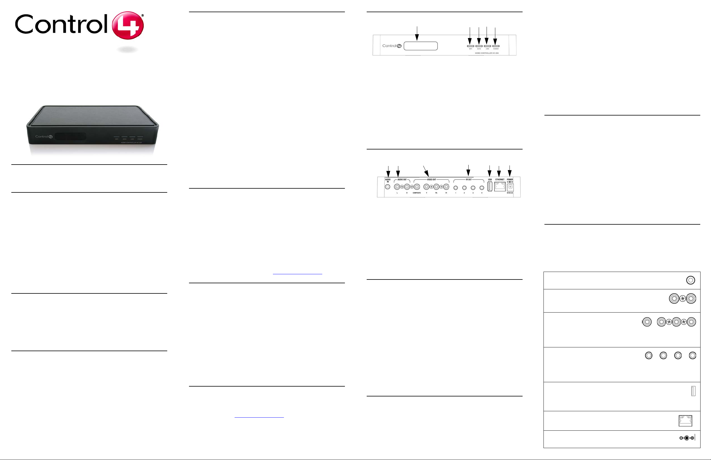
Front View
1. IR Window / IR Blaster—For capturing third-party IR codes from hand-
held devices (such as remote controls) or blasting IR codes. The WiFi
LED blinks red when capturing IR codes.
2. WiFi LED—This LED blinks first red, then orange, and then blue during
the boot process. Once the operating system is running, the WiFi driver
changes the LED color depending on the signal strength of its connection
to its associated access point. Colors and signal strength are as follows:
orange = Fair to Good, blue = Excellent, and no light = No connection.
3. Data LED—This blue LED indicates streaming audio is received.
4. Link LED/Identification button—Blue LED light indicates Home Controller has been identified in a Control4 Composer project. Press this button to identify this device in Composer.
5. Power LED—Blue LED light indicates AC power is present. It turns on
immediately after the power is applied to the device.
1 2 3 4 5
Back View
1 2 3 4 5 6 7
1. Audio In (1 left-right pair)—3.5 mm jacks for stereo channel input (line
level) for one stereo analog source.
2. Audio Out (1 left-right pair)—RCA jacks for stereo channel line output
(line level) for amplifiers or audio switches.
3. Video Out—Composite RCA and Component RCA jacks.
4. IR Out (4 sets)/Serial (optional, 2 sets)—3.5 mm jacks for up to four IR
output transmitters or for up to two optional serial devices, such as a
receiver or disk changer. Jacks 1 and 2 are configurable.
5. USB (1 port)—For external storage device with USB support (such as
FAT32 formatted devices) or WiFi adapter (C4-NWA-11G-USB).
6. Ethernet—RJ-45 jack for a 10/100 BaseT Ethernet connection.
7. Power plug port—DC power supply port
Install the HC-200
To install this controller:
1. Ensure that your home network is in place before starting your sys-
tem setup: The Home Controller HC-200 requires a network connection
(wired or WiFi) in order to use all features as designed. When connected,
the Home Controller can access Web-based media databases and
Control4 system updates.
2. Connect the HC-200 controller to the network: To connect using an
Ethernet connection, plug the data cable from the home network connection into the Home Controller RJ-45 port (labeled “Ethernet”) and the network port on the wall or at the network switch. To connect using the
optional USB WiFi adapter (C4-NWA-11G-USB), refer to the installation instructions shipped with the adapter.
3. Power up the controller: Plug the DC power supply into the Home Controller power plug port and an electrical outlet.
4. Connect system devices as described in the “Connect Devices” section that follows.
Mount the HC-200 on a Wall (optional)
1. Mount HC-200 horizontally using 2 standard single-gang wall boxes:
The wall mounting plate has four horizontal sets of slots. Install two single-gang wall boxes so that they will align with set 1 and set 4, using the
wall mounting plate as a template. Leave the screws protruding []” from
the wall.
Mount the HC-200 horizontally or vertically using 1 standard double-
gang box: Install a standard double-gang box. Leave the screws protrud-
ing []” from the wall.
Mount the HC-200 horizontally or vertically using 4 screws (not provided) placed directly into a wall stud or studs: Using the mounting
plate as a template, screw four screws into a stud (for vertical positioning)
or two studs (for horizontal positioning) to align with slots 1 and 4. Leave
the screws protruding []” from the wall.
2. Use the four screws (provided) to attach the mounting plate to the bottom
of the controller. Ensure that the narrow end of the slots will be on top
when the device is installed (not applicable to mounting device directly
into wall vertically).
3. Arrange the wires in the wire paths on the mounting plate. [How do they
need to be arranged?]
4. Line the slots on the mounting plate up with the screws.
5. Press the device onto the scres and slide down (or over if mounting
device directly into wall vertically) until the screws are in the narrow end
of the slots.
Configure the HC-200
Set Up Media Storage
To set up media storage on the controller or using an external device, use
Control4 Easy Importer on a connected computer. (Install Easy Importer
from the installation CD included with your controller.) See Easy Importer
Help for more information.
Configure Video Output Mode
The default video output mode is NTSC over composite. In this mode, there
is some bleed-through of the NTSC signal on the component video output
connections. However, the video image will not appear correctly in this
mode. The HC-200 can be configured to output over component using NTSC
(standard definition) or 720p (high definition). To configure the video mode to
use the component video outputs, in Composer, make the appropriate
bindings for the desired video output mode.
Connect Devices
NOTE: You can use Composer software to step through the connection
process before or after the physical connections are complete.
Connect all applicable devices to the Home Controller HC-200 using one of
the connection options described in the following table.
Table 1. Connection Options
Audio In (1 left-right pair)—3.5 mm jacks for stereo channel
input (line level) for one stereo analog source
Audio Out (1 left-right pair)—RCA jacks for stereo
channel line output (line level) for amplifiers or audio
switches
Video Out Options—Composite or Component port for displaying navigation menus on
a monitor or TV. The Component jack is
used for displaying standard or high-definition video. T o display st andard
definition video, use the Composite port.
IR Out (4 sets)/Serial (optional, 2 sets)—
3.5 mm jacks for up to four IR output transmitters or serial devices, such as a receiver
or disk changer. See “Set Up IR Emitters or IR Blaster” for more
information.
USB (1 port)—For external storage device with USB support (such
as FAT32 formatted devices). See “Set up External S torage Device”
for more information or for connecting the optional WiFi adapter
C4-NWA-11G-USB.
Ethernet—RJ-45 for a 10/100 BaseT Ethernet connection
Power plug port—For use with the DC power supply (pro-
vided)
Page 2
Connect the IR Ports/Serial Ports (optional)
The HC-200 provides four IR ports, two of which can be reconfigured for
serial communication. Connect a device to the HC-200, like a receiver or
disk changer using the special serial cable (optional). Serial ports support
many different band rates but do not support hardware flow control.
To configure a port for serial or for IR, make the appropriate connections in
your project using Composer.
Set Up IR Emitters or IR Blaster
Your system may contain third-party products that are controlled with IR
commands (usually through remote controls). T o provide a way for the Home
Controller to control a device that only recognizes IR commands, complete
one of the following setups: IR Emitters or IR Blaster.
IR Emitters
1. Plug the 3.5 mm connector end of one of the four IR stick-on emitters provided into an IR Out port on the HC-200.
2. Place the stick-on emitter end over the IR receiver on the media player,
TV, or other target device to drive IR signals from the HC-200 to the target.
IR Blaster
In addition to IR emitters, the HC-200 is also equipped with an IR blaster,
which is located just left of the front LEDs. To use the blaster instead of an IR
emitter:
1. In Composer, connect Front IR Out of the Home Controller to the IR In of
the device you wish to control.
2. Test and verify that the HC-200 is positioned in such a way that the
blaster can reach the device you wish to control.
Troubleshooting
To reset the HC-200, press and hold the identify button until the WiFi LED
blinks orange, signaling the start of the boot process.
To reset to network defaults (wired connection), power cycle the HC-200 and
hold the identify button until the Data, Link, and Power LEDs are solid blue,
then immediately release.
If during the boot sequence, the WiFi LED stays orange, press and hold the
identify button until the LED blinks blue, then release.
Regulatory Compliance
This product has been designed and tested to the following U.S., Canadian,
European, Australian, and New Zealand standards:
IMPORTANT! Any changes or modifications not expressly approved by the
party responsible for compliance could void the user’s authority to operate
this equipment.
IMPORTANT! Tous les changements ou modifications pas expressément
approuvés par la partie responsable de la conformité ont pu vider l'autorité
de l'utilisateur pour actionner cet équipement.
WICHTIG! Alle mögliche Änderungen oder Änderungen nicht ausdrücklich
genehmigt von der Partei, die für Befolgung verantwortlich ist, konnten die
Berechtigung des Benutzers aufheben, um diese Ausrüstung zu betreiben.
and on, the user is encouraged to try to correct the interference by one of the
following measures:
• Reorient or relocate the receiving antenna.
• Increase the separation between the equipment and receiver.
• Connect the equipment into an outlet on a circuit different from that to
which the receiver is connected.
• Consult the dealer or an experienced radio/TV technician for help.
Edison Test Lab (ETL)
This product has been tested by ETL and has been found to be in
compliance with:
UL60065, 7th Edition, 2006 + A1; 2006—Audio video and
similar electronic apparatus - safety requirements
CSA C22.2 No. 60065-03 1st Edition—Audio video and
similar electronic apparatus - safety requirements
Industry Canada
This Class B digital apparatus complies with Canada ICES-003.
Cet appareil numérique de la classe B est conforme à la norme NMB-003 du
Canada.
CAN/CSA-C22.2 No. 60065-03 1st ed., 2006-04 +A1: 2006 (Audio, video,
and similar electronic apparatus)
Canadian ID 7848A-C4HC200E
Europe: CE Declaration of Conformity
European Contact Information
Control4 UK Limited
Unit 3, Green Park Business
Centre
Sutton-on-the-Forest, York
YO61 IET, United Kingdom
+44 (0) 134781 2300
c4@control4-UK.com
Product: Home Controller HC-200
The undersigned hereby declares, on behalf of Control4 Corporation, that
the above-referenced product, to which this declaration relates, is in
conformity with the provisions of:
• Council Directive 89/336/EEC (May 3, 1989) on Electromagnetic Compatibility
• Council Directive 1999/5/EC (Mar 9, 1999) on Radio & Telecommunication Terminal Equipment (R&TTE)
• Council Directive 73/23/EEC (Feb. 19, 1973) on Low Voltage Equipment
Safety
• Council Directive 93/68/EEC (Jul. 22, 1993) Amending Directives 89/336/
EEC and 73/23/EEC
and has been tested to the requirements of, and shown to be in compliance
with, the following requisite standards:
• IEC 60065/EN 60065 - 2002 Audio Video and similar electronic apparatus
• EN 55022: 2006 Information Technology Equipment
• EN 55024: 1998 + A1: 2001 Information Technology Equipment—Immunity characteristics—limits and methods of measurement.
This product is susceptible to RF interference.
The T echnical Construction File required by these Directives is maintained at
the corporate headquarters of Control4, Salt Lake City, Utah, U.S.A.
Signed,
Brett Molen—Vice President, July ___, 2008
United States Contact Information
Control4 Corporation
11734 S. Election Road, Suite 200
Salt Lake City, UT 84020-6432,
USA
Tel (801) 523-3100
Warranty
Limited 2-year Warranty. Refer to http://www.control4.com/warranty.
About This Document
Copyright © 2008 Control4 Corporation. Control4 and the Control4 logo are
registered trademarks of Control4 Corporation. All trademarks are properties
of their respective owners. Part Number: 200-00085 Rev A Draft 4
North America
Federal Communications Commission (FCC)
FCC ID: R33C4HC2001—This device complies with Part 15 of the FCC
Rules. Operation is subject to the following two conditions: (1) This device
may not cause harmful interference, and (2) this device must accept any
interference received, including interference that may cause undesired
operation.
This equipment has been tested and found to comply with the limits for a
Class B digital device, pursuant to Part 15 of the FCC Rules. These limits are
designed to provide reasonable protection against harmful interference in a
residential installation. This equipment generates, uses, and can radiate
radio frequency energy and, if not installed and used in accordance with the
instructions, may cause harmful interference to radio communications.
However, there is no guarantee that interference will not occur in a particular
installation. If this equipment does cause harmful interference to radio or
television reception, which can be determined by turning the equipment off
Norsk: Apparatet må tilkoples jordet stikkontakt.
Suomi: Laite on liitettävä suojamaadoituskoskettimilla varustettuun
pistorasiaan.
Svensk: Apparaten skall anslutas till jordat uttag.
Dansk: Vigtigt! Lederen med grøn/gul isolation må kun tilsluttes en klemme
mærket eller
Australian / New Zealand
• AS/NZS CISPR 22: 2002—Information Technology Equipment—Radio
disturbance characteristics.
Recycling
For recycling information, please go to www.control4.com/recycling.
 Loading...