

Page 1
Bus Power Supply, 48V
Installation Guide
Introduction
The Control4® Bus Power Supply (C4-DIN-BPS48) is intended for use in a Control4
system. This device installs in a Control4 Centralized Lighting panel or in any
standard DIN rail panel with 35 mm rails. The Bus Power Supply provides the
power to the Bus Ethernet Gateway (C4-DIN-BEG) and Control4 wired keypads
(C4-KCB-xx and C4-SKCB-xx) in a Centralized Lighting system.
Package contents
• Bus Power Supply
• Pluggable Terminal Block (1)
• Bus Power Supply Installation Guide (this document)
Requirements and specifications
Before installing this product, make sure that the Control4 5-Slot or 2-Slot Panel
(or other cabinet) to house the power supply has been installed.
Part number
Power input
Power output
Power consumption
Connectors
Operating temperature
Humidity
Storage
Dimensions
DIN module width
Weight
Shipping weight
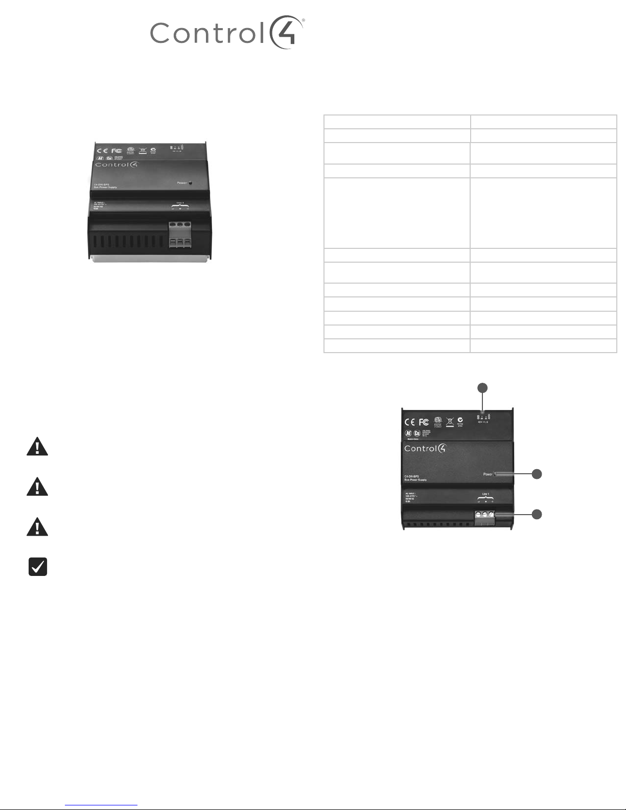
Front view
C4-DIN-BPS48
100-277VAC / 1.25A
48 VDC 1.2A (120-277V)
48 VDC 1.0A (100-120V)
75W, 120V/1.0A; 277V/0.6A
One RS-485 Pluggable Terminal Block
36AWG to 14 AWG (0.14 mm to 1.5 mm)
One Line Voltage Screw Terminal
• One Line
• One Neutral
• One Earth Ground
• One 26 AWG to 12 AWG
(0.12 mm to 4 mm)
32˚F ~ 104˚F (0˚C ~ 40˚C)
5% - 95%
Non-condensing
-4˚F - 158˚F (-20˚C ~ 70˚C)
4.23 × 4.48 × 2.32˝ (107.5 × 113.9 × 59 mm)
6M
1.3 lbs. (0.589 kg)
1.7 lbs. (0.770 kg)
A
Warnings and considerations
Warning! Improper use or installation can cause SERIOUS INJURY,
DEATH or LOSS/DAMAGE OF PROPERTY.
Attention ! Une mauvaise utilisation ou installation peut entraîner des
blessures graves, décès ou perte / dommages à la propriété.
Warning! This device must be protected by a circuit breaker
(20A max).
Attention ! Cet appareil doit étre protègè par un disjoncteur
(20A max.)
Warning! Disconnect the power for all lines feeding into the panel
before installing this product.
Attention ! Couper le courant électrique pour tous les disjoncteurs
d’alimentation dans le panneau avant d’installer ce produit.
Important! The Bus Power Supply should be installed by a licensed
electrician in accordance with all national and local electrical codes.
B
C
Figure 1: Front view
A Pluggable terminal connector
B Power LED
C Line voltage connector
Page 2
Preparing to install
Before you install in a Control4 panel:
1 Use Composer Pro to add the Bus Power Supply to a project, define its
location in a panel, and print the Panel Report. See the Composer Pro User
Guide for details.
2 Install the panel following the instructions in the 5-Slot and 2-Slot Panel
Installation Guide.
3 Install and wire the Terminal Block for the Bus Power Supply following the
instructions in the Terminal Block Installation Guide and in the location
defined by the Composer Pro panel reports.
Note: Third-party panels do not require a Terminal Block.
Before you install into a third-party DIN rail panel:
1 Install the third-party panel according to the third-party instructions.
Installing the power supply
To install the power supply into a Control4 panel:
1 With the pluggable terminal connector facing right, hold the power supply
upright and angle it to the right so that the right side of the module fits onto
the rail in the panel.
2 With the right side already in place, press forward on the left side of the Bus
Power Supply to snap it onto the rail (see Figure 2).
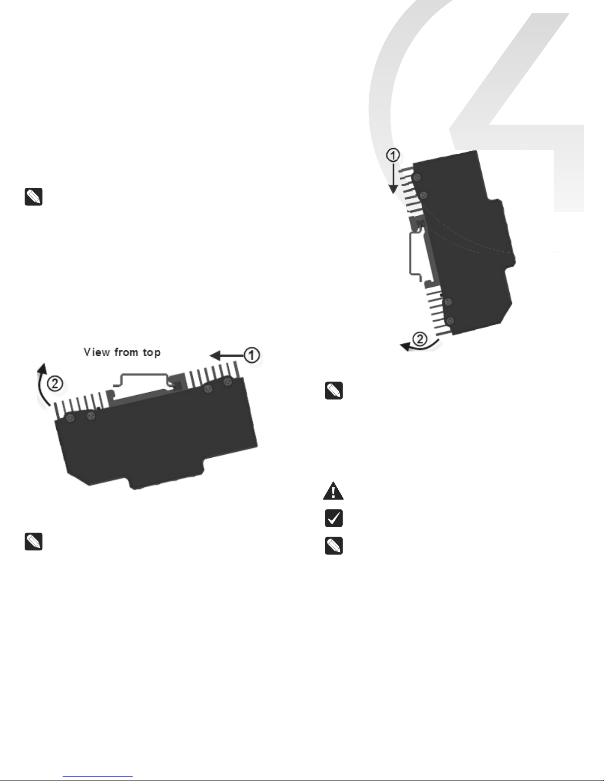
To install the power supply into a third-party panel:
1 With the pluggable terminal connector facing up, hold the power supply
lengthwise and angle it up so that the top side of the module fits onto the
rail.
2 With the top side already in place, rotate the power supply down to snap it
onto the rail (see Figure 3).
Figure 2: Snap on the Bus Power Supply - Control4 panels
Note: To remove the module, press the module toward the bottom,
rotate the module up, and lift it o.
Figure 3: Snap on the Bus Power Supply—third-party panels
Note: To remove the module, press the module toward the bottom,
rotate the module up, and lift it o.
3 Install the other modules into the panel as defined in their respective
installation guides.
Wiring instructions
See Figure 4 on the next page to view the wiring diagram. Read the Keypad Bus
Wiring Guide (
ctrl4.co/buswiring
Warning! When wiring the RS-485 Pluggable Terminal Connector, make
sure that either the Line level power is OFF or that the connector is not
connected.
Important: All wires between the Pluggable Terminal Block and the
Bus Power Supply must use the same gauge wire as the field wiring
connected to the Pluggable Terminal Block.
Note: Wiring between the Pluggable Terminal Blocks and the module
will be easiest when stranded wire is used.
• At the Terminal Block side, strip the wires 0.35˝ (9 mm) and tighten
to 7 in-lb (0.8Nm).
• At the module side, strip the wires 0.3˝ (7 mm) and tighten to
5.3in-lb (0.6Nm).
) for full wiring details.
Page 3

To Keypads
(Max 40 Keypads, Max 1000 ft / 304 m)
(Max 35 Keypads when running at 100VAC input)
GND D
_
D+ V+
Bus Power Supply
Figure 4: Bus Power Supply wiring diagram
GND D
_
D+ V+ GND D
Bus Ethernet Gateway
LED indicators
The indicator lights on the front of the Bus Power Supply communicate the status
of the device.
Indicator Color Status
Power
Status
Blue Device is on
Black Device is o
Red
Flashing red
Red means voltage below
36V (too many keypads)
Flashing red means overload
or short circuit
Troubleshooting
Symptom Possible solution
Module does not power on.
Make sure the module is connected securely
to the Mains power supply.
_
D+ V+
Additional resources
The following resources are available for additional support:
• Control4 Knowledgebase and forums
• Control4 Technical Support
• Control4 website:
• Composer documentation available at
For the latest version of this document, open these URLs or scan the QR code on
a device that can view PDFs.
Regulatory/Safety information
To review Regulatory information for your particular Control4 products, see the
information located on the Control4 website at
Patent information
MOST RECENT VERSION
www.control4.com
ctrl4.co/docs
ctrl4.co/reg
KEYPAD BUS WIRING GUIDE
.
.
ctrl4.co/bps48
Applicable patents are available at
Warranty
Visit
ctrl4.co/warranty
for details.
ctrl4.co/patents
ctrl4.co/buswiring
.
Page 4

control4.com | 888.400.4070
Copyright ©2016, Control4 Corporation. All rights reserved. Control4, the Control4 logo,
the 4-ball logo, 4Store, 4Sight, Control4 My Home, and Mockupancy are registered
trademarks or trademarks of Control4 Corporation in the United States and/or
other countries. All other names and brands may be claimed as the property of their
respective owners. All specifications subject to change without notice.
200-00371-D
2016-07-27 MS
D
 Loading...