

Page 1
™
The previous procedure should be repeated anytime that a module is rewired or a
load type changes.
NOTE: Once the module has been identified into a project, it is no longer
possible to configure the dimming mode from the module. The dimmable/
non-dimmable load type and dimming mode settings in Composer must
be used to configure the dimming mode.
NOTE: When first identifying a module into a project, if the dimming
mode of the light in Composer conflicts with the dimming mode of the
corresponding channel on the module, a warning will be presented forcing
the user to choose the appropriate dimming mode.
Composer Pro Configuration and Reports
Use Composer Pro to define the properties of each 8-Channel Dimmer, its location
in a panel, and the loads that are connected to it. Composer Pro can then be used
to generate Panel Reports, Module Reports, and Load Schedule Reports. These
reports are essential to ensuring that each 8-Channel Dimmer is properly installed
in the correct location and wired to the appropriate loads. Please refer to the
Composer Pro User Guide for detailed information.
Browser Configuration Tool
Basic properties for each load as well as the network configuration for the
8-Channel Dimmer can be set using a standard web browser. To open the
configuration page, simply start the browser and type in the IP address of the
dimmer. Alternatively, the Properties page for the module in Composer Pro has a
link to the browser configuration page.
The browser configuration tool can be used to set the following properties:
• Network Settings
- DHCP Enable/Disable
- IP Address
- Subnet Mask
- IP Gateway
• Control Settings for each Channel
- Dimmable/Non-Dimmable (locked out once identified into a project)
- Dimming Mode (locked out once identified into a project)
- Click Ramp Rate Up/Down
- Hold Ramp Rate Up/Down
- Minimum & Maximum Levels
- Preset Level
- Cold Start Level
- Module Override Level
Additionally, the browser configuration tool can be used to view the current
temperature of the dimmer as well as any channel short circuit faults.
LEDs
During normal operation, the indicator lights on the front of the 8-Channel Dimmer
communicate the status of the device.
Indicator LED Color Status Notes
Module Override Blue Power on, normal
operation
Black O
Red Thermal overload See “Faults” section
below
Channels Blue Load on
Black Load o
Red Short Circuit Fault See “Faults” section
below
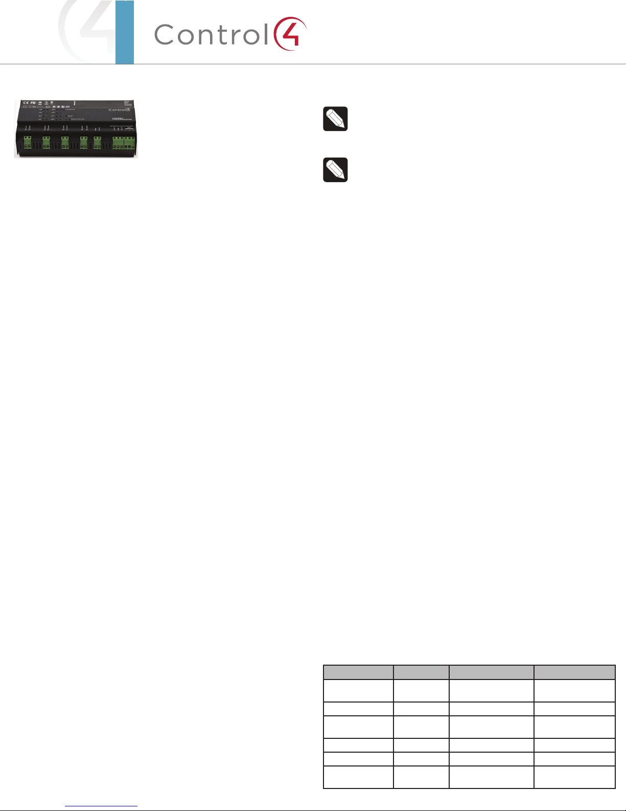
Supported Model
• C4-DIN-8DIM-E 8-Channel Dimmer
Introduction
The Control4® 8-Channel Dimmer controls up to eight (8) devices from one
module in the Control4 system. It installs in a panelized backbox using typical
wiring standards and communicates to the Control4 system using a CAT5 Ethernet
connection.
Dimming Mode Configuration
Each channel on the 8-Channel Dimmer can be set to several dierent dimming
modes:
• Switch Mode: Only allows the load to be set to 100% or o.
• Autodetect Mode: The dimmer will detect the load type and set forward or
reverse-phase dimming appropriately.
• Forward Phase Mode: Forces the channel into forward-phase (leading edge)
dimming.
• Reverse Phase Mode: Forces the channel into reverse-phase (trailing edge)
dimming.
The Autodetect, Forward Phase, and Reverse Phase modes should only be used
with dimmable loads.
In its factory default state, all channels on the 8-channel Dimmer are set to “Switch
Mode” to prevent inadvertent dimming of non-dimmable loads.
The mode can be configured for each channel using the buttons on the front of the
module:
1 Press the CH1 and CH8 buttons simultaneously.
2 All channel LEDs will change color indicating the current dimming mode:
• Solid Yellow – Switch Mode
• Solid Red – Autodetect Mode
• Solid Green – Forward Phase Mode
• Solid Blue – Reverse Phase Mode
3 Click each channel button to cycle through the four (4) dimming mode types.
4 Once each channel is set as desired, click the Module Override button to
initiate the autodetect sequence on any channels set to ‘Autodetect Mode.’
The channel being autodetected will blink Red. When the autodetect test is
finished, the channel LED will go to one of the following states:
• Blinking Green – Autodetected forward phase
• Blinking Blue – Autodetected reverse phase
• Solid Red – Autodetect failed. Run the test again or set an alternate
mode.
5 Exit the configuration mode by pressing and holding the Module Override
button briefly. If any channels are still set to Autodetect (solid red), the
autodetect sequence will run for those channels.
8-Channel
Dimmer
Operation and
Configuration
Guide
Page 2
Indicator LED Color Status Notes
Link/Activity Solid Green Link
Orange Activity
Flashing
Green
Firmware updating Flashing gets faster
as update proceeds
Channel and Module Override Buttons
During normal operation, the buttons on the front of the 8-Channel Dimmer
behave in the following manner:
Button Action Result
CH1-CH8 Click Toggles the load on and
o.
Hold Ramps/fades the load (if
dimmable).
Module Override Click Toggles between the
module override scene
and all channels o.
Hold for five (5) seconds Sets the module override
scene to current channel levels. The Module
Override LED will blink
rapidly to indicate that
the override scene has
been saved.
The following button tap sequences are available using the CH1 and CH8 buttons.
Function CH1 CH8 CH1
Identify 4
Reboot Device 15
Factory Reset 9 4 9
Reset Button
NOTE: The Reset button is recessed and must be pressed using a
paperclip or similar device.
A single click of the Reset button is equivalent to powering the 8-Channel Dimmer
o and back on. Additionally, certain special activities can be accomplished by
pressing and holding a specific button while clicking the Reset button. Note that
the same activity is possible by pressing and holding the designated button while
power cycling the 8-Channel Dimmer:
Hold Button While
Clicking Reset
Result
CH7 Sets the device to DHCP-disabled and forces the IP
address to 192.168.1.200.
CH8 Toggles between DHCP-enabled and DHCP-disabled.
Module Override Restores the factory image (do not perform unless
directed to do so by Control4 Technical Support).
Faults
The 8-Channel Dimmer is designed to protect itself and the attached load(s)
through certain fault conditions. These fault conditions are indicated via the LEDs
on the front of the device and are available through the driver for the device as
properties and variables.
Overtemp Fault
• Occurs if the module reaches an unsafe operating temperature.
• Is generally an indication that the device is over its load ratings.
• All loads attached to the module will turn o.
• The Module Override LED will turn red.
• The fault condition cannot be cleared nor loads turned back on until the
device has reached a safe operating temperature. Once the device has
reached a safe operating temperature, the fault will automatically clear. Note,
though, that loads will not automatically turn back on after the fault has
cleared.
Overcurrent Fault
• Occurs if a significantly large current spike happens on an individual channel.
There are several reasons why this could occur:
- A true short circuit occurs (e.g., nail hits wires)
- The attached load has an excessively high in-rush current
- The attached incandescent bulb burns out creating a large current spike
- A non-dimmable load is dimmed (particularly non-dimmable CFLs and
LEDs)
• The load attached to the faulted channel will turn o.
• The Channel LED will turn red.
• To clear the fault, simply turn the load back on via the appropriate channel
button on the front of the module or via a keypad (or any other action) that
has been programmed to control the load.
• If the same fault occurs within 10 seconds of clearing the fault, the fault
condition is considered to be ongoing and must be addressed before
proceeding. After addressing the underlying problem, the fault can be cleared
by pressing and holding the Channel button for five (5) seconds. Composer
Pro can also be used to clear the fault condition.
Manual Overrides
Prior to installation of the control system, or in case a problem occurs with the
control system or the network, it is possible to control the loads attached to the
8-Channel Dimmer via several methods:
• Override Scene
- The module override scene is stored in the module itself and does not
require interaction from the control system.
- The default setting for this override scene is all loads on at 100%.
- The override scene settings can be changed using the buttons on the
front of the module (see the “Channel and Module Overrides” section
above), the Browser Configuration Tool, or Composer Pro.
• Module Override Button
- Clicking the Module Override button toggles the attached loads between
the stored override scene and all loads o.
• Auxiliary Override Contacts
- The Aux In and Aux Out terminals on the 8-Channel Dimmer can be wired
to a standard line-voltage toggle switch installed in a hidden but convenient
location, such as a closet.
- Each time the attached switch is flipped, the 8-Channel Dimmer will toggle
between the stored override scene and all loads o.
- If desired, a single toggle switch can be wired to the Aux In contact on
multiple Control4 Panelized Lighting modules, but all modules sharing an
auxiliary override switch MUST BE ON THE SAME ELECTRICAL PHASE.
- The desired location of the Auxiliary Override Switch can be defined in
Composer Pro for each module. This information will appear in the Module
Report generated by Composer Pro.
• Channel Override Buttons
- The channel override buttons on the front of the module provide individual
control of each load attached to the 8-Channel Dimmer. Click the specific
Channel Override button to toggle the load between its preset level and o.
Press and hold the specific Channel Override button to ramp/fade the load (if
dimmable).
Page 3

™
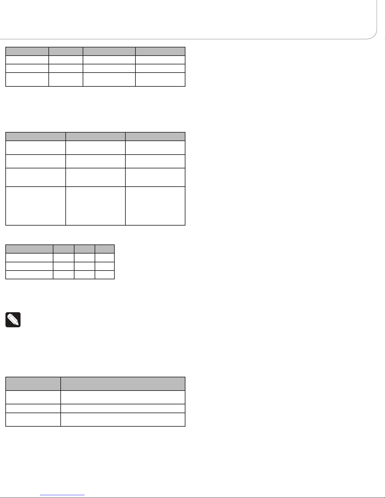
Troubleshooting
Symptom Possible Solution
Module does not
power on
Verify that the circuit breaker is on.
Verify that Line-In 1 is connected to the power.
Load does not turn on Verify that the load is wired to the proper channel
terminal.
Verify that the channel is not in a fault condition (see
“Faults” section above).
Verify that the light bulb is not burned out.
Loads do not turn o Verify that the Terminal Block jumpers that connect
the black Terminal Block to the red Terminal Blocks
have been removed.
Module overheats Verify that the load ratings have not been exceeded.
Verify that the module is receiving proper ventilation.
About this Document
Part Number: 200-00321, Rev A 1/17/2013
Page 4

Copyright ©2013 Control4. . All rights reserved. Control4, the Control4 logo, the Control4 iQ logo and the Control4 certified logo are registered trademarks or trademarks of Control4 Corporation in
the United States and/or other countries. All other names and brands may be claimed as the property of their respective owners Pricing and specifications are subject to change without notice
 Loading...