

Page 1
Wireless Dimmer,
600 W att, No-Status
Installation Guide
Supported Models
C4-6NDIM1-Z Wireless Dimmer, 600 Watt, No-Status
Specifications and Supported Fixtures
This Control4® Wireless Dimmer, 600 Watt, No-Status operates independently or as part
of a Control4 Home-Automation System to enable intelligent lighting control. It inst alls in a
standard wall box using typical wiring standards and communicates with other devices
through a wireless RF (radio frequency) connection.
Power:
Supported Load
Types and
Ratings:
Operating Temperature:
Volume:
Communications:
• 120 VAC +/-10% 50/ 60 Hz
• 350 mW
• 120 VAC 600 W Incandescent ( all types)
• 120 VAC 600 W Halogen (all types)
• 120 VAC 600 W Forward Phase Controlled
Electronic Low Voltage (dimmable only)
• 120 VAC 600 W Forward Phase Controlled
Fluorescent Light Fixtures (dimmable only)
• 120 VAC 600 VA Forward Phase Controlled
Magnetic Low Voltage (al l types wit h 70 percent or
greater load factor)
• Total minimum load must exceed 25W
• This device can function with or without a neutral
AC connection (see relevant wiring diagrams).
However, when controlling Magnetic Low Voltage
loads, a neutral wire connection is required.
• All load ratings are based on an ambient
temperature of 25 degrees Celsius.
• 5.0 Cubic inches
• ZigBee, IEEE 802.15.4, 2.4 GHz, 15-channel,
spread spectrum radio
IMPORTANT! This product generates heat during normal operation.
IMPORTANT : Ce produit produit la chaleur pendant l'opération normale.
IMPORTANT! Use or modification of this product in a manner not expressly
approved by Control4 voids your warranty. Further, Control4 is NOT liable for
any damage incurred with the misuse of this product. See "Limited 2 Year
Warranty."
IMPORTANT : l'Utilisation ou la modification de ce produit dans une manière
pas expressément approuvée par les vides Control4 votre garantie. De plus,
Control4 n'est pas responsable pour aucun dommage encouru avec le mauvais
usage de ce produit. Voir "Limited 2 Year Warranty."
IMPORTANT! The range and performance of the wireless control system is
highly dependent on the following: (1) distance between devices; (2) layout of
the home; (3) walls separating devices; an d (4) electrical equipment located
near devices.
IMPORTANT : la gamme et la performance du système de contrôle sans fil
dépendent hautement de la chose suivante : (1) la distance entre les artifices;
(2) la disposition de la maison; (3) les murs séparant des artifices; et (4)
l'équipement électrique se positionnait près des artifices.
Installation Instructions
1 Turn OFF the power by switching off the circuit breaker or re moving
the fuse and testing that the power is off before wiring!
2 Ensure that the Dimmer capacity matches the load requirement s. In
multi-Dimmer installations, a reduction of the Dimmer's capacity is
required to allow the Dimmers to be installed side-by-side in the
same wall box. The Dimmer capacity depends on the number
"ganged" in the wall box as follows:
• 1 gang = 600 W / VA maximum
• 2 gang = 500 W / VA maximum per dimmer
• 3 or more gang = 400 W / VA maximum per dimmer
If installing in multi-gang scenarios, use pliers to re move the
inner-side break-away tabs: Bend each one back and forth
until it breaks off. Remove the inner-side t abs ONLY on any
device side that will be adjacent to another device. DO NOT
remove tabs on any side that will become the outer side of
a group of devices.
3 Identify your wiring application and see the appropriat e diagram in "Sample Wiring
Configurations."
• Single-Location Scenario—Power Source at Wall Box
• Single-Location Scenario—Power Source at Light Fixture
4 Prepare wires by removing the pre-cut insulation
from the appropriate Dimmer leads. Wire
insulation should be stripped back 5/8 of an inch
from the wire end (as shown).
5 Connect the Dimmer wires to the wall box wires
using the wire nuts according to the rele vant wiring
diagram. See “Sample Wiring Configurations.”
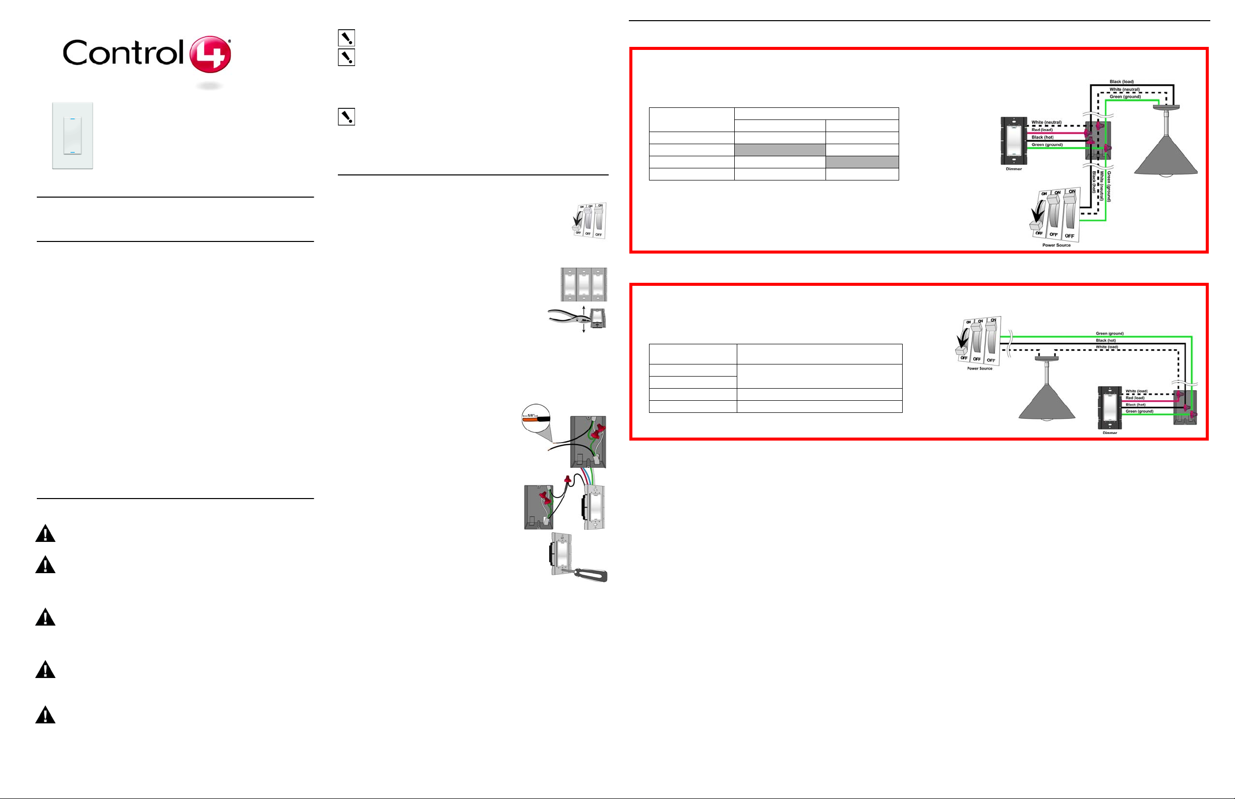
Sample Wiring Configurations
Single-Location Scenario—Power Source at Wall Box
To wire the dimmer for a Control4 single-location scenario in which
the power is first routed to the wallbox, connect together and cap with
a wire nut the wires indicated in the following table:
Dimmer Wires
White (neutral) White (neutral) White (neutral)
Red (load)
Black (hot) Black (hot)
Green (ground) Green (ground) Green (ground)
From Power Source To Light Fixture
None black (load)
Single-Location Scenario—Power Source at Light Fixture
T o wire the dimmer for a Control4 single-location scenario in which the
power is first routed to the light fixture electrical box, connect together
and cap with a wire nut the wires indicated in the following table:
Dimmer Wires Wires in the Wall Box
White (load)
Red (load)
Black (hot) Black (hot)
Green (ground) Green (ground)
(from the Light Fixture)
White (load)
Wires in the Wall Box
None
Warnings & Considerations
WARNING! Risk of Electric Shock. Install in accordance with all regional,
national, and local electrical codes.
AVERTISSEMENT : Risque de Décharge électrique. Installez conformément à
tous des codes électriques régionaux, nationaux et locaux.
WARNING! Risk of Serious Injury, Death, or Property Damage or Loss. Install
and use properly—as described in this document—to avoid danger of injury,
death, or property damage or loss.
PRÉVENANT : le Risque de Blessure Sérieuse, Mort, ou Dommage de Propriété
ou Perte. Installez et utilisez correctement comme décrit dans ce document —
pour éviter le danger de blessure, mort, ou do mmage de p ropriété ou perte .If you
are unsure about any part of these instructions, consult a qualified electrician.
WARNING! Risk of Serious Injury, Death, or Property Damage or Loss. If you
are unsure about any part of these instructions, consult a qualified electricia n.
PRÉVENANT : le Risque de Blessure Sérieuse, Mort, ou Dommage de Propriété
ou Perte. Si vous êtes peu sûrs d'une partie de ces instructions, consultez un
électricien qualifié.To reduce the risk of overheating and possible damage to this
device and other equipment, DO NOT inst all to control a r eceptacle , a mot or, or a
transformer-operated appliance.
CAUTION! Risk of Overheating. To reduce the risk of overheating and possible
damage to other equipment, do not install to control a receptacle, or a motoroperated appliance.
PRUDENCE : Risque du fait de surchauffer. Po ur réduire le risque du fait de
surchauffer et du dommage possible à d'autre équipement, n'installez pas pour
contrôler un réceptacle, ou un appareil opéré de moteur.
WARNING! Risk of Electrical Fire. Use this device only with copper or copper
clad wire. Do not use aluminum wiring. This product has not been approved for
use with aluminum wiring.
AVERTISSEMENT : Risque de Feu Électrique. Utilisez cet artifice seulement
avec le fil habillé couleur cuivre ou couleur cuivre. N'utilisez pas d'installation
électrique en aluminium. Ce produit n'a pas été approuvé pour l'utilisation avec
l'installation électrique en aluminium
6 Mount the Dimmer into the wall box by partially
securing the wall box screws attached to the Dimmer.
Ensure that the word "Top" on the Dimmer frame is facing
up. Bend the wires in a zigzag pattern so that they easily
fold into the wall box.
Page 2
WARNING! Ground the Wireless Dimmer in accordance with the National
Electric Code (NEC) requirements. Although the dimmer's aluminum yoke plate
and green ground wire are directly bonded together inside the dimmer, DO NOT
rely solely upon the yoke plate's contact with a metal wall box for adequate
grounding. Use the dimmer's ground wire to make a secure connection to the
safety ground of the electrical system.
AVERTISSEMENT : Risque de Décharge électrique. Fondez [l'artifice]
conformément au Code Électrique national (NEC) les exigences. Bien que la
plaque de joug en aluminium du variateur et le fil de garde vert soient direct ement
bonded ensemble intérieurs au variateur, ne dépendez pas uniquement sur le
contact de plaque de joug avec une boîte murale en métal pour les bases
adéquates. Utilisez le fil de garde du variateur pour faire une connexion sûre à la
terre de sécurité du système électrique.
IMPORTANT! Not grounding this product according to the preceding may result
in an installation less immune to damage caused by electrical disturbances, such
as lightning, and void the warranty.
IMPORT ANT : Pas les bases de ce produit selon la précédence peuvent
s'ensuivre dans une installation moins immunisée pour nuire provoqué par les
troubles électriques, comme la foudre et le vide la garantie.
7 If you are using the Control4 push-on (screw-less) wall plate that shipped with your
Dimmer:
a. For a single-gang scenario, attach the black plastic sub-plate using the
provided sub-plate screws.
IMPORTANT! Tighten the screws until the back side of the metal yoke plate
is even with the wall surface, but no farther. Over-tightening can damage the
dimmer and cause mechanical malfunction. Do NOT use a power screw driver
to install this device as this may lead to over-tightening.
IMPORT ANT : Serrez les vis jusqu'à ce que la face ar rière de la plaque de joug
en métal soit même avec la surface murale, mais pas plus loin. Le fait de
surserrer peut nuire au variateur et provoquer le mauvais fonctionnement
mécanique. N'utilisez pas de chauffeur de vis de pouvoir pour installer cet
artifice comme cela peut causer le fait de surserrer.
b. If you are insta lling in a multi-gang scenar io, onl y pa rtially t ighten the mountin g
screws, leaving about 1/8 of an inch gap between the wall and the yoke plates
prior to attaching the black plastic sub-plate. This al lows each device i n a multigang scenario to conform to the sub-plate, creating a single assembly. Secure
the multi-gang sub-plate to all devices using the provided sub-plate screws.
Then secure the assembly by tightening the wall box screws the r emaining 1/8
of an inch. Do not over-tighten any of the screws, or you will misalign the flat
plane of the multi-gang wall plate.
c. With the wall plate's removal slot facing down, push the wall plate
onto the Dimmer's black plastic sub-plate.
8 If you are using a Decora-style screw-on wall plate:
a. Do not attach the Dimmer's black plastic sub-plate.
b. Align the Dimmer to the wall box and fasten it with screws.
c. Fasten the wall plate to the Dimmer with screws.
9 Turn ON the power at the ci rcui t breake r or repla ce the f use from fuse
box.
10 Test the Dimmer to ensure it is working properly. See "Operation and
Configuration" for specific instructions.
Operation and Configuration
On initial power up, the
unit will flash the Red/
Green/Blue (RGB) LEDs,
which can be programmed
with different colors for
different states or color
preferences. To set up this
Dimmer for use with a
Control4 system, refer to
your system setup
documentation.
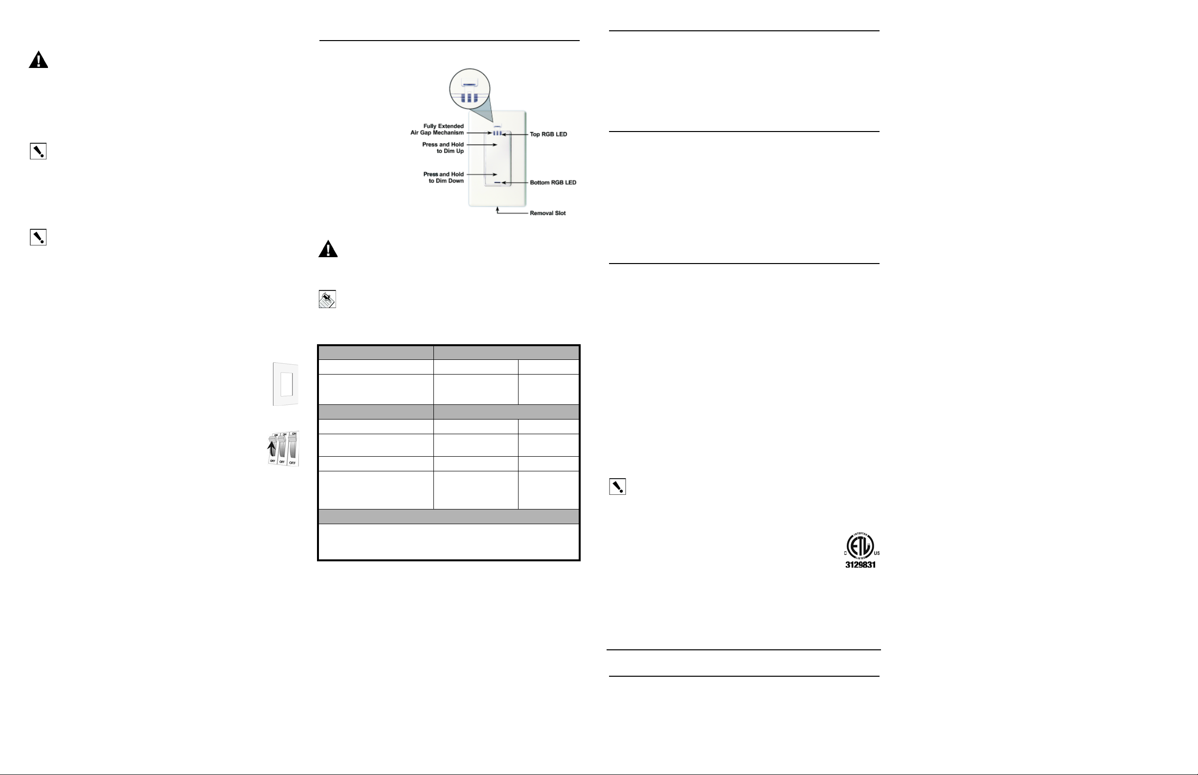
WARNING! Prior to changing a light bulb or performing any other
maintenance to the light fixture, pull up on the Air Gap Mechanism with your
fingernail to cut power to the light fixture.
AVERTISSEMENT : Risque de Décharge électrique. Avant de changer une
ampoule ou exécuter autre maintenance à l'in st allation claire, tirez en haut sur
le mécanisme de trou aérien avec votre ongle pour couper le pouvoir de
l'installation claire.
NOTE: The Dimmer feels warm to the touch under normal conditions.
To operate and configure this Dimmer as a stand-alone device, refer to the following
table.
Change Light Bulb or Fixture Default Behavior of RGB LEDs:
To cut power to the fixture: Top Bottom
Pull up on the Air Gap Mechanism
and fully extend (about 0.3 of an
inch) to cut power to the light fixture.
Operate Dimmer Default Behavior of RGB LEDs:
To operate dimmer: Top Bottom
Turn ON (full brightness): Tap the
top.
Turn OFF: Tap the bottom. Not lit Lit
Set the dimming level: Press and
hold the top or bottom button until
the desired lighting level is reached,
and then release.
Care and Cleaning
Do NOT paint the Dimmer or its wall plate.
Do NOT use any chemical cleaners to clean the Dimmer.
Clean surface with a soft damp cloth as needed.
Not lit Not lit
Lit Not lit
Lit Not lit
Troubleshooting
If the light does not turn on:
• Ensure at least one (1) LED on the face of the Dimmer is lit.
• Ensure the light bulb is not burned out and is screwed in tightly.
• Ensure the circuit breaker is not turned OFF or tripped.
• Check for proper wiring (see “Sample Wiring Configurations”).
• For help on the installation or operation of this product, e -mail or call the Control4
Technical Support Center. Please provide your exact model number. Contact
support@control4.com or see the web site www.control4.com.
Limited 2 Year Warranty
Control4 Corporation ("Control4") warrants that at the time of first-consumer sale, this
product will be free from defects in material and manufacture. Control4 further warrants
that for a period of 2 years (24 months) after init ial consumer sale, th e product will f unction
in accordance with its specification, provided that it is installed and maintained under
normal and proper use. This warranty extends only to products purchased directly from
Control4 or an Authorized Control4 Reseller. If the product proves to be defective in
material or workmanship during the warranty period, it may be returned to the place of
purchase and Control4 will, at its sole option, repair or repla ce the product with a li ke
product. This warranty provides the consumer purchaser with specific legal rights, which
may vary per state or country. For complete warranty information, including details on
consumer legal rights as well as warranty exclusions, visit www.cont rol4.com/warranty.
Regulatory Compliance
FCC
FCC ID: R33C4DIM1Z
This device complies with Part 15 of the FCC Rules. Operation is subject to the following
two conditions: (1) this device may not cause harmful interference, and (2) this device
must accept any interference received, including interference that may cause undesired
operation.
This equipment has been tested and found to comply with the limits for a Class B digital
device, pursuant to Part 15 of the FCC Rules. These limits are designed to provide
reasonable protection against harmful interference in a residential installation. This
equipment generates, uses, and can radiate radio frequency energy and, if not installed
and used in accordance with the instructions, may cause harmful interference to radio
communications. However, there is no guarantee that interference will not occur in a
particular installation. If this equipment does cause harmful interference to radio or
television reception, which can be determined by turning the equipment off and on, the
user is encouraged to try to correct the interference by one or more of the following
measures:
• Reorient or relocate the receiving antenna.
• Increase the separation between the equipment and receiver.
• Connect the equipment into an outlet on a circuit different from that to which the
receiver is connected.
• Consult the dealer or an experienced radio/TV technician for help.
IMPORTANT! Any changes or modifications not expressly approved by the
party responsible for compliance could void the user’s authority to operate this
equipment.
IMPORTANT : N'importe quels changements ou modifications pas expressément
approuvées par le parti responsable de l'acquiescement pourraient le vide
l'autorité de l'utilisateur pour faire marcher cet équipement.
ETL Statement
ETL Control Number: 3129831
This product has been tested by ETL and was found to comply with:
• UL 1472, First Edition, “Standard for Solid State Dimming Controls”
• CSA C22.2 No. 184.1, First Edition, “Solid State Dimming Controls”
Industry Canada
IC: 7848A-C4DIM1Z
This Class B digital apparatus complies with Canada ICES-003.
Cet appareil numérique de la classe B est conforme à la norme NMB-003 du Canada.
Protected under U.S. Patents D518,446, 7,335,8 45, 7,106,261, 7,336,463
About this Document
United States Patent s Pending. ©2009 Control4. A ll rights reserved. Control4, the Control4
logo and Everyday Easy are registered trademarks or trademarks of Control4 Corporation
in the United States and/or other countries. All other names or brands may be claimed as
property by their respective owners. Pricing and specifications subject to change without
notice. Part Number: 200-00143 Rev A 5/19/2009
 Loading...