

Page 1

™
8×8 HDMI Matrix Switch
Installation and Setup
Guide
Supported Model
• C4-8x8HDMIVSW-B 8×8 HDMI Matrix Switch
Introduction
The Control4® 8x8 HDMI Matrix Switch enables up to eight (8) HDMI
inputs to be distributed to eight (8) zones, with Ethernet passthrough and IR and RS232 control.
• Enables up to eight (8) AV sources for multi-room AV
distribution via full-matrix switching
• System control is enabled through Ethernet, giving installation
flexibility for new or retrofit installations
• Easily installed with Control4 Simple Device Discovery Protocol
(SDDP)
• 2U rack-mount ears conform to EIA 19" rack standards
Source inputs
HDMI 8
HDBaseT Ethernet inputs 8
Zone outputs
HDBaseT outputs 8
HDMI outputs (exclusive-or of
HDBT 7/8)
Stereo audio output (3.5 mm
stereo jack)
RS232 serial ports 8
IR ports 8 (IR frequency: 38 KHz)
Operational temperature 32˚F ~ 104˚F (0˚C ~ 40˚C)
Humidity 5% to 95% non-condensing
Storage -4˚F ~ 158˚F (-20˚C ~ 70˚C)
Dimensions 13.4" x 10.1" x 3.9"
Weight 8.64 lbs (3.92 kg) (unit only)
Shipping weight 12.48 lbs (5.66 kg)
HDBaseT Receiver
Model number C4-HDBTE-B
Voltage 12VDC
Current 1.5A
Dimensions 4.0" x 4.8" x 0.9"
Weight 1.3 lbs (0.6 kg) (unit only)
Shipping weight 3.0 lbs (1.35 kg) (box & power
2
8
Control
Environmental
Miscellaneous
(341 x 257 x 100 mm) (w/feet)
13.4" x 10.1" x 3.6"
(341 x 257 x 91 mm) (no feet)
(box, power supply & cord)
(102 x 123 x 23mm) (w/mount)
supply)
Box Contents
• 8×8 HDMI Matrix Switch (C4-8x8HDMIVSW-B)
• Power cord and external power supply
• Warranty card
• Rack-mount ears (2)
• Four (4) 8-32 x 3/8" Phillips screws
• Four (4) feet (pre-attached), which can be removed for device
rack mounting.
Available Accessories
• HDBaseT Receiver (C4-HDBTE-B)
Specifications
HDBaseT Receiver
Model number C4-8x8HDMIVSW-B
Voltage 12VDC
Current 8.5A
Network connectivity 10/100 BaseT Ethernet
Full matrix switching Yes
Rack-mount Yes, 2U rack-mount ears included
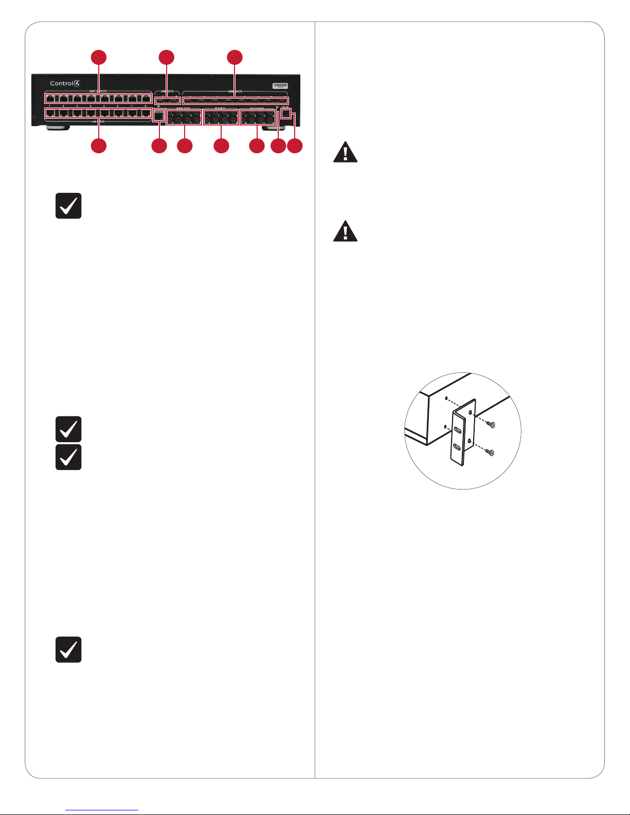
Front and Rear Panel Description
Front Panel
C
B
A
LED Indicators
A Status—One blink=unable to obtain IP address from DHCP
server. O indicates normal operation.
B Link—Indicates a connection to Director.
C Power—Flashes while booting. Solid blue when powered on.
1
Page 2
Back Panel
CBA
D E F G H I J
A HDBT OUTPUTS—Connect a HDBaseT Receiver (C4-HDBTE-B)
to these ports. Carries video, audio, Internet, and commands over
CAT5e/6 cable.
IMPORTANT! Cable length cannot exceed 328 feet (100
meters) from switch to receiver.
B HDMI OUTS—Connect HDMI-compatible playback devices to these
ports. These are shared outputs for zones 7 and 8 (using HDMI OUT
7 and 8, respectively). Zones 7 and 8 can either be HDBT or HDMI
out (not both at the same time).
C HDMI INPUTS—Connect HDMI sources (audio, video, or both) to
these ports.
D LAN PORTS—Connect Ethernet-compatible playback or network
devices to these ports. These port numbers correspond to the
HDBT OUTS. There is a one-to-one input to output on the HDBaseT
Receiver. Any of these ports in use needs to be connected to a
network switch. On the receiver side, they will connect the LAN
port to the device or network switch.
E IP control port—Connect the home network (via a router or
Ethernet switch) to this port.
F AUDIO OUTS—Connect 1/8" (3.5mm) plug-compatible audio
switches or amplifiers to these ports. These are a mirrored output
of the stereo audio for the respective zone. (The stereo audio
occurring in zone 1 [the HDBaseT Receiver connected to HDBT
port1] will also occur in the analog stereo output 1.)
NOTE: These are stereo only. Multi-channel audio will not
play out of these ports.
Installation
Essential setup tasks include:
1 Disconnecting power to the switch
2 Installing the rack-mount bracket
3 Connecting the input and output devices
4 Connecting the device to the network and power
5 Setting up the connections in Composer Pro
WARNING! Disconnect power to the switch and connected
devices while making connections. Reconnect power only when
the connections are complete.
ATTENTION ! Coupez l’alimentation à l’interrupteur et les
périphériques connectés lors des connexions. Rebranchez
uniquement lorsque les connexions sont terminées.
CAUTION! Do not run HDBaseT/Zone CAT5e/6 cabling with
or in close parallel proximity to mains power cables, or severe
signal interference may result.
ATTENTION ! N’installez pas le câblage HDBaseT / Zone
CAT5e / 6 avec ou à proximité immédiate parallèle à un câbles
d’électricité, ou des interférences de signaux graves peuvent en
résulter.
Installing a Rack-mount Bracket
1 Align the holes on each bracket with the holes on the HDMI switch,
then mount the brackets using four (4) 8-32 x 3/8” flat-head screws
(included).
IMPORTANT! Audio cable length should not exceed 10 feet
(about 3 meters).
G IR PORTS (pass-through)—Allow 38kHz IR data to be passed from
a controller to an HDBaseT Receiver, or from an HDBaseT Receiver
to the switch. Uses standard 1/8” (3.5 mm) IR cable.
• When a controller is connected to the switch’s IR port, a stereo
mini jack cable must be used.
• When an IR emitter is connected to the switch or the HDBaseT
Receiver, it must be the mono mini-jack emitter (available from
Control4).
• If the IR is going from the receiver to the switch, then the
capture device connected to the receiver must be an IR receiver
and cannot be a Control4 controller.
H RS-232 PORTS—Allow control to be sent from a controller to the
output of an HDBT Receiver. They can be used with a 1/8” (3.5mm)
accessory cable (C4-CBL3.5-DB9B). If connecting to the serial
ports on an HC-250, you can use a stereo 3.5 mm-to-3.5 mm cable.
These port numbers correspond to their respective zone output.
IMPORTANT! Serial cable length should not exceed 10 feet
(about 3 meters).
I ID button—Press to identify the device for Composer Pro system
setup.
J Power Port—Connect the included power adapter here. Use only
the included power adapter. (DIN, 12VDC) When connecting, slide
back the locking connector and orient the plug flat side down.
Connect Input and Output Devices
Refer to any device-specific documentation for additional installation
instructions.
To connect:
1 Connect the source devices to the HDMI INPUTS and other inputs.
Each numbered input connection associates to the same HDBT
port. Example: The HDMI INPUT #1, IR PORT #1, and RS232 PORT #1
ports all associate with the HDBT OUTPUT #1 port.
2 When connecting a controller to the HDMI switch via RS-232:
a. If connecting an HC800, use a 1/8” (3.5mm) accessory cable
(C4-CBL3.5-DB9B).
b. If connecting an HC250, use a stereo 3.5 mm-to-3.5 mm cable.
3 Connect the HDBT OUTPUT port to the HDBASET INPUT port on
the HDBaseT Receiver (C4-HDBTE-B).
4 Connect the appropriate LAN, IR, and RS-232 serial connections
from the receiver to the display device (such as a TV, receiver, or
projector).
For RS-232, the switch/receiver combination is configured as a null
modem. Consequently, you may not need a null modem cable or
adapter if the display device usually requires one.
2
Page 3

Connect to the Network and Power
HDCP video (solid=HDCP-protected
video passing through, flashing=unprotected video, o=no video)
HDBaseT link (solid=active,
steady flash=power saving,
random flickering/o=error)
Power (slow blink=power on)
Source Device
1 Plug the Ethernet cable from the home network connection into
the HDMI switch’s IP control port.
2 Connect the included power adapter into the switch’s power
connector. When the power adapter is connected, the HDMI
switch powers on.
Set Up the Connections
Use Composer Pro to set up the bindings. See the Composer Pro User
Guide for details, or refer to the Documentation tab in the device driver.
NOTE: A zone must be locked to enable 3D features and
multi-channel audio (including lossless formats).
Using the HDBaseT Receiver
Indicators
Network Switch
HDBaseT Receiver
(example: controller)
HDMI (output)
LAN (pass-through)
RS232
IR (pass-through)
3
Page 4

™
Calibrating
Calibrating gathers information from all connected devices for faster
switching times. For the best experience, always perform a calibration as
soon as all devices are connected. The system should also be calibrated
after any new devices (source or zone equipment) are added or port
allocations changed. Failure to correctly calibrate the system may cause
interruption to zone audio and video when other zones are switched to a
source that is already in use.
To calibrate your switch:
1 Manually power on all devices connected to the switch inputs and
outputs, and set them to the appropriate inputs.
2 In Composer Pro, click the Calibrate button on the driver’s Actions
tab. This process may take several minutes, depending on the
number of devices connected. To view calibration status, view the
Calibration Status field on the driver’s Properties tab.
NOTE: Calibration forces all switch video outputs to the
lowest TV/display common denominator. This calibration is
bypassed when an output zone is locked to a source.
Troubleshooting
Resets
• Reboot—Disconnect the power adapter to reboot (power cycle) the
device.
Restore
• Factory Restore—Power o the switch, then press and hold the ID
button while reconnecting power. Continue to hold the ID button
until the status (left-most) LED on the front flashes rapidly. During
the factory restore process, the status LED stays solid, and the
power (right-most) LED flashes slowly.
Regulatory/Safety Information
To review Regulatory information for your particular Control4 products,
see the information located on the Control4 website at:
http://www.control4.com/regulatory/.
Warranty
For complete warranty information, including details on consumer legal
rights as well as warranty exclusions, review the Warranty card or visit
www.control4.com/warranty.
control4.com |
4
©2013 Control4. All rights reserved. Control4, the Control4 logo, the Control4 iQ logo and the Control4 certified logo are registered trademarks or trademarks of Control4 Corporation in
the United States and/or other countries. All other names and brands may be claimed as the property of their respective owners. #200-00002-LEA Rev. A 8/28/2013 MS
 Loading...