

Page 1
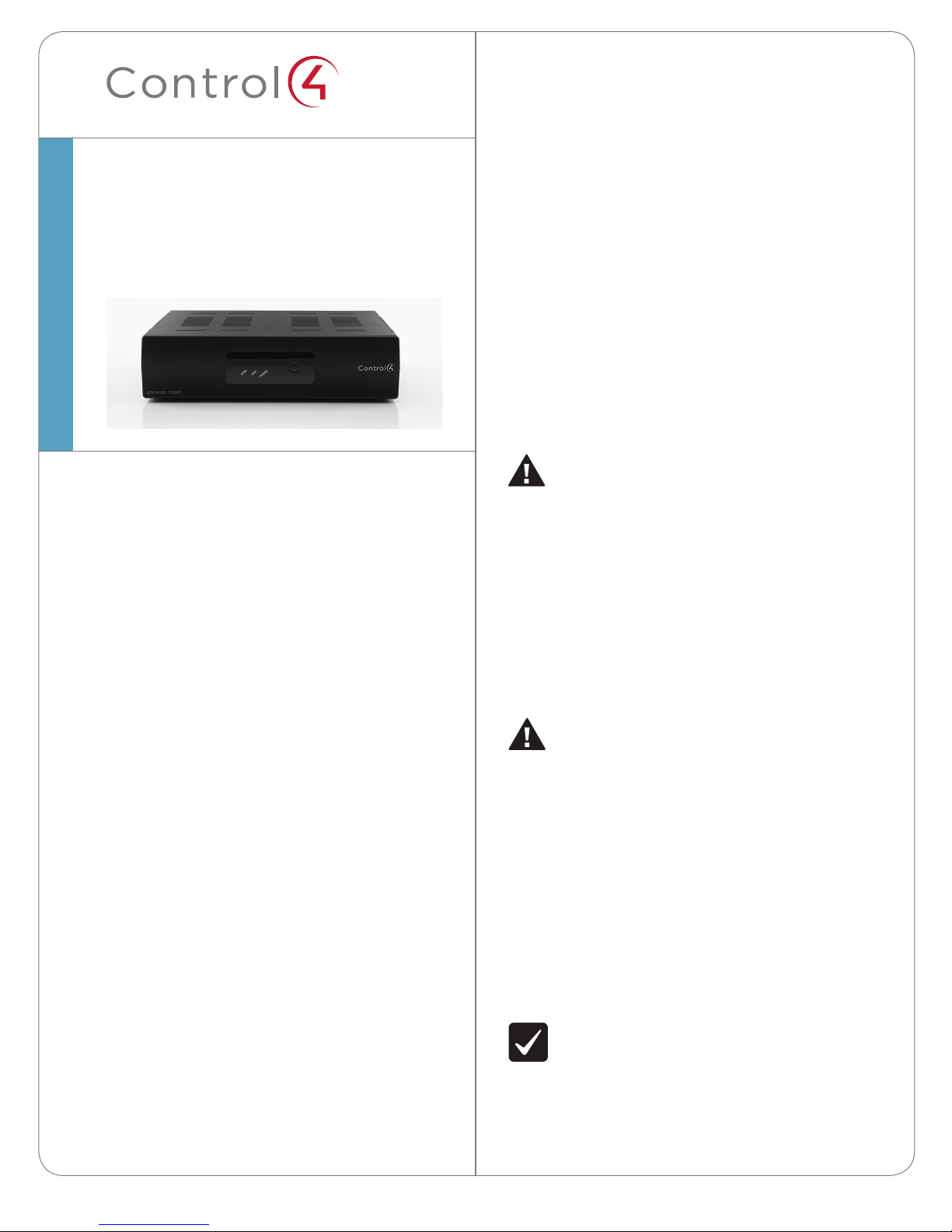
Speaker Point™
Installation Guide
Supported Models
• AVE-RAA1-B Ethernet Speaker Point
• AVG-RAA1-B WiFi Speaker Point
Introduction
™
The Speaker Point has one stereo speaker pair output
and one analog line-level output to feed an external
power amplifier, which can independently operate
dierent audio and volume controls. The on-board
digital 50 watt per channel amplifier powers local
bookshelf, wall, or other speakers. You can control
the Speaker Point output using Control4 Navigation
devices.
Box Contents
• AC to DC Power Adapter
• AC Power Cord
• Vertical Mounting Base
• Warranty card
Warnings
WARNING! To reduce the risk of electrical
shock, do not expose this apparatus to rain or
moisture.
AVERTISSEMENT! Pour réduire le risque de
choc électrique, n’exposez pas cet appareil à la
pluie ou à l’humidité.
The Control4® Speaker Point is an end point in
a Control4 digital audio distribution system that
converts and amplifies the digital audio stream to
drive speakers in remote locations throughout the
home. It accommodates ease in adding new audio
zones to a new or existing home without running
speaker cable back to a central amplifier.
The Speaker Point takes direction from the Control4
controller. It can also receive digital or analog signals
from other devices, such as a CD or DVD players that
are being controlled by the Control4 controller. It may
act as an amplifier or pass the audio signal digitally to
another Control4 audio endpoint for amplification.
The Speaker Point is designed with a compact profile
and small footprint so you can place it in a way where
it won’t easily be seen, such as on a bookshelf, an
overhead plant shelf, or even mounted in attic space.
The unique design allows you to place it horizontally
or mount it vertically with either the special vertical
mounting base (included) or hung from a wall using
the mounting holes in the bottom of the chassis.
WARNUNG! Um das Risiko des elektrischen
Schlages zu verringern, setzen Sie diesen
Apparat nicht Regen oder Feuchtigkeit aus.
WARNING! Do not expose the apparatus to
dripping or splashing. Do not place objects
filled with liquids near the apparatus.
AVERTISSEMENT! N’exposez pas l’appareil à
l’égoutture ou à l’éclaboussement. Ne placez
pas les objets remplis de liquides près de
l’appareil.
WARNUNG! Setzen Sie den Apparat nicht
Bratenfett oder dem Spritzen aus. Setzen Sie
nicht die Gegenstände, die mit Flüssigkeiten
nahe dem Apparat gefüllt werden.
IMPORTANT! Using this product in a manner
other than outlined in this document voids
your warranty. Further, Control4 is NOT liable
for any damage incurred with the misuse of
this product. See “Limited 2 Year Warranty.”
1
Page 2

™
WICHTIG! Um übermäßige Hitze zu erzeugen
zu vermeiden, stapeln Sie Lautsprecher-Punkte
nicht auf einander oder andere Ausrüstung.
For general information about the product, see the
Product pages at http://www.control4.com.
Speaker Point
Installation Guide
IMPORTANT ! Employer ce produit en quelque
sorte autre que décrit dans ce document vide
votre garantie. De plus, Control4 n’est pas
responsable d’aucun dommage encouru avec
l’abus de ce produit. Voyez que « a limité la
garantie de 2 ans. »
WICHTIG! Das Verwenden dieses Produktes in
gewissem Sinne anders als umrissen in diesem
Dokument hebt Ihre Garantie auf. Weiter ist
Control4 NICHT für irgendeine Beschädigung
verantwortlich, die mit der Fehlanwendung
dieses Produktes genommen wird. Sehen Sie,
daß „begrenzte eine 2 Jahr-Garantie.“
IMPORTANT! To ensure good connections,
when using banana connectors, make sure
binding posts are screwed in completely.
IMPORTANT ! Assurer de bons raccordements,
à l’aide des connecteurs de banane,
s’assurent que des poteaux liants sont vissés
complètement.
Product Specifications
Inputs and Outputs • Audio output: 1 stereo pair
speaker out, 1 stereo line level
pre-amp out
• Audio input: 1 stereo line level
Power Amp Output • 25W/channel THD+N <
0.30%, 20Hz to 20kHz, both
channels driven into 8 ohms
(FTC)
• 50W/channel THD+N <
1%, 20Hz to 20kHz, both
channels driven into 8 ohms
(Peak)
Digital Audio to
Amplified Stereo Out
Analog Line to
Amplified Stereo Out
Communications • Ethernet 10/100base-T, RJ-45
Environmental • Operational 0ºC to 40ºC
Power Requirements • AC Supply: 100-240 VAC,
Dimensions • H x W x D: 2.23” x 8.65” x
Weight
• Frequency response: 20
Hz to 20 kHz, +0.5/-0.5 dB
(48kHz Sample Rate)
• S/N Ratio: 103 dB
• Frequency response: 20 Hz
to 18.5 kHz, +0.5/-1.5 dB
• S/N Ratio: 88 dB
jack
• Wireless IEEE 802.11g WiFi
(WiFi model only)
• Humidity 5% to 95% Non-
Condensing
• Storage -20ºC to 70ºC
60/50 Hz, 1 A
• DC Input: 36 VDC @ 3.75 A
8.65”
• Weight: 1.8 lbs
WICHTIG! Gute Anschlüsse sicherzustellen,
wenn es Banane Stecker verwendet, stellen
sicher daß bindene Pfosten vollständig
eingeschraubt werden.
IMPORTANT! To avoid generating excessive
heat, do not stack Speaker Points on top of
each other or other equipment.
IMPORTANT ! Pour éviter de produire de la
chaleur excessive, n’empilez pas les points
de haut-parleur sur l’un l’autre ou tout autre
équipement.
2
Additional Resources
The following resources are available for additional
support.
• Control4 Knowledgebase or Forums
• Control4 Technical Support
• Control4 website: http://www.control4.com
• Composer documentation in online help or PDF
format available on the Dealer portal
Page 3

Front View
Figure 1. Front View
line in for audio source (e.g., a CD player).
5 Ethernet. Ethernet RJ-45 port for device control
and configuration of an audio and digital stream.
6 USB (1 port). (Future) for an external storage
device with USB support (such as FAT32formatted devices).
Installation Instructions
2
1
1 IR window (Future). For capturing third-party IR
codes from hand-held devices (such as Control4
System Remote Control devices).
2 Data LED. Red LED light indicates music is
currently streaming in or out.
3 Link LED. Red LED light indicates a network
connection is present.
4 Power LED. Red LED light indicates when power
is present. LED turns on approximately 30
seconds after the power is applied to the device.
5 Identification/Reset button. For identifying this
device to the system during initial setup and as a
device reset button when pressed for 10 seconds
or more.
3
5
4
Back View
Connect all applicable devices to the HC-800 using
the connection options described next.
Figure 2. Back View
1 Connect a left and right speaker to the Left and
Right speaker ports. The speakers should be
rated to handle a minimum of 50 W RMS each to
avoid damaging the speakers.
2 (Optional) Connect an audio source, such as a CD
player, to the Audio port.
IMPORTANT! Do not attach any amplified
audio output to the Audio In port.
IMPORTANT ! N’attachez aucune sortie audio
amplifiée à l’acoustique dans le port.
WICHTIG! Bringen Sie keine verstärkte
Audioleistung zum Audio im Tor an.
3 (Optional) Connect the pre-amp Audio Out port
to the inputs of an external power amplifier.
4 Connect the DC connector of the power supply
to the Speaker Point.
5 Plug the AC power cord into the power cord
receptacle on the power supply.
6 Plug the AC power cord into a standard 120 VAC
outlet to power up the Speaker Point.
7 Check the Speaker Point status using its front
panel LEDs.
4
2
1 Power plug port. DC power supply port
(+36VDC@3.75A).
2 Right and Left Speakers. Right and left speakers
each with five-way binding post (+Red/-Black)
for passive speakers.
3 Audio Out. Line level Audio Out RCA (pre-amp)
port for another zone of audio.
4 Audio In. Line level Audio In RCA port for analog
31
Data
Link
Power
5
6
8 Ensure that the installation site is network-ready
with an Ethernet and/or a WiFi network. For
more detail, see the Composer topic, “Guidelines
for Setting up a Wired or Wireless Network.”
9 Connect the Speaker Point to an Ethernet
Category 5 cable to set up the Ethernet
connection. Note that for the WiFi Speaker Point
setup, you need to have a temporarily connect
the Speaker Point to Ethernet.
On = Music is streaming to or from this device.
On = Network connection established.
On = Power is Present. This LED will turn on about
30 seconds after the power is applied to the device.
3
Page 4

10 If your choice for networking your Speaker Point
is Ethernet with DHCP, skip to Step 11. Otherwise,
follow these instructions:
a Connect to Local Director.
b From the Tools menu, select System
Manager.
c From the Devices pane (left pane), select the
network address for the device you want to
set up the network configuration and click
Connect. If the device’s network address is
not on this list, click Refresh. If it still does not
appear, click Add to enter it manually. If you
do not know the network address, find it at
the Connections view > Network tab.
d Select the Network tab and click Configure.
e Click Next when a Network Configuration
Wizard dialog appears. Continue through
the wizard screens and provide the following
information appropriate for system. Much of
this information has to match that of your
Wireless Access Point (WAP).
- Enter new device name. Do not include
spaces in the new name.
- Indicate kind of network: Wireless (WiFi)
network.
- Indicate Method for obtaining DNS
server address: DCHP or Static IP. Control4
recommends DHCP (automatically).
- Enter the SSID.
- Enter the WEP key (if any).
- Enter the encryption type (64 or 128).
- Click on a Key type, hex or ascii.
f Click Finish to complete the wizard and
reboot the Speaker Point to apply the
network configuration changes.
11 Configure the Speaker Point within the Composer
software. See the Composer topic, “Configure a
Speaker Point—Ethernet or Wireless” for detailed
information.
any of the Touch Screens. When you use any
navigation device, ensure that the room you
are trying to control is the room selected in
the navigation device. If necessary, refer to the
“Change Location” procedure in the System User
Guide.
13 If you are using the WiFi to communicate to your
Control4 Controller, disconnect the Ethernet
Category 5 cable.
Regulatory/Safety Information
To review regulatory information for your particular
Control4 products, see the information located on
the Control4 website at: http://www.control4.com/
regulatory/.
Warranty
Limited 2-year Warranty. Go to http://www.control4.
com/warranty for details.
About This Document
Part number: 200-00040, Rev. E, 03/06/2012
NOTE: Treble, Bass, and Balance, as well as
the initial Volume level, are set in the System
Design view of Composer by double-clicking
the Speaker Point object to access the
controls screen.
12 After you have set up this device in the
Composer software, you can control the audio
output from this Speaker Point using any of
the navigators, such as On-Screen Navigator or
control4.com |
4
©2012 Control4. All rights reserved. Control4, the Control4 logo, the Control4 iQ logo and the Control4 certified logo are registered trademarks or trademarks of Control4 Corporation in
the United States and/or other countries. All other names and brands may be claimed as the property of their respective owners.
™
 Loading...