

Page 1
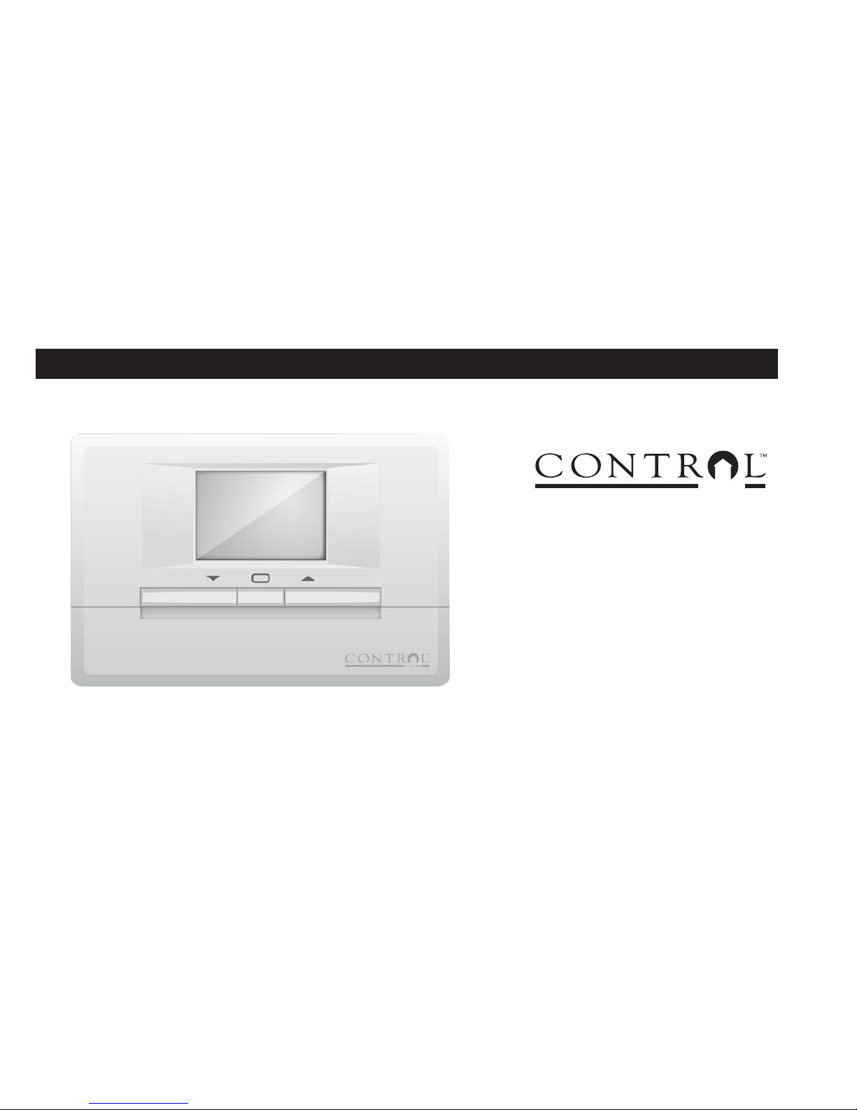
5+2 Day Programmable Thermostat
For single stage heating, cooling or millivolt heating systems
IMPORTANT:
This thermostat is NOT compatible with any 120V or 240V high voltage control system.
Read and understand this manual before installation or use.
Instruction Manual
model: M6003
Low-voltage (24 V or millivolt)
system control
BY/PAR
CANARM
Page 2
1
2
3
4
5
6
6
7
8
9
10
11
12
13
13
15
16
17
18
19
21
21
26
27
Table of Contents
Introduction and features
Warning and safety precautions
Product Overview
Compatibility
Introduction
Tools required for installation
Choosing the location for the new thermostat
Replacing the old thermostat
Mounting the back plate
Connecting the wires to the terminals
Wiring diagram
Setting the fan operation jumper
Installing batteries
Attaching the back plate
Function key description
LCD display
Introduction
Pre-programmed settings
Heating program
Cooling program
Programming operations
Troubleshooting
Warranty
Features
Installation
Operation
Programming
Supplementary Info.
Page 3
2
• Large LCD display with backlight
• Real-time clock showing day, hour and minute - in selectable 12 or 24 hour display format
• Separate weekday, weekend programs with 4 programs per day
• Separate heat / cool programs with built in protection for the air-conditioner compressor
• Display and set temperature in ºC or ºF
• Interface with heating or air-conditioning systems for automatic temperature control
• Low battery notication by ashing icons and Beep sound
Features
Package Contents:
M6003 Thermostat
Instruction Manual (This Document)
2 Screws
2 Wall Anchors
FOR LOW-VOLTAGE CONTROL
SYSTEMS
DO NOT CONNECT TO
HIGH-VOLTAGE LINE
Page 4

3
Features
Warning & Safety Precautions
• Read this instruction manual thoroughtly prior to the installation and the use of the thermostat.
• Follow all instructions in this manual.
• Keep this instruction manual for future reference.
• Clean the thermostat only with a dry cloth.
• Do not operate this thermostat with wet hands.
• Do not block any ventilation openings of the thermostat.
• Do not expose this thermostat to dripping or splashing.
• Do not expose this thermostat to excess heat.
• Do not attempt to disassemble, repair or modify this thermostat.
THIS PRODUCT MUST BE INSTALLED IN ACCORDANCE WITH THE CANADIAN ELECTRICAL
CODE. IN QUEBEC, THIS PRODUCT MUST BE INSTALLED BY A QUALIFIED ELECTRICIAN.
The manufacturer assumes no responsibility for imporper wiring, or any resulting damages.
Improper installation by a non-professional automatically voids the warranty.
Page 5
4
Product Overview
• This thermostat requires two AA size batteries (not included) to operate. Ensure the batteries are installed.
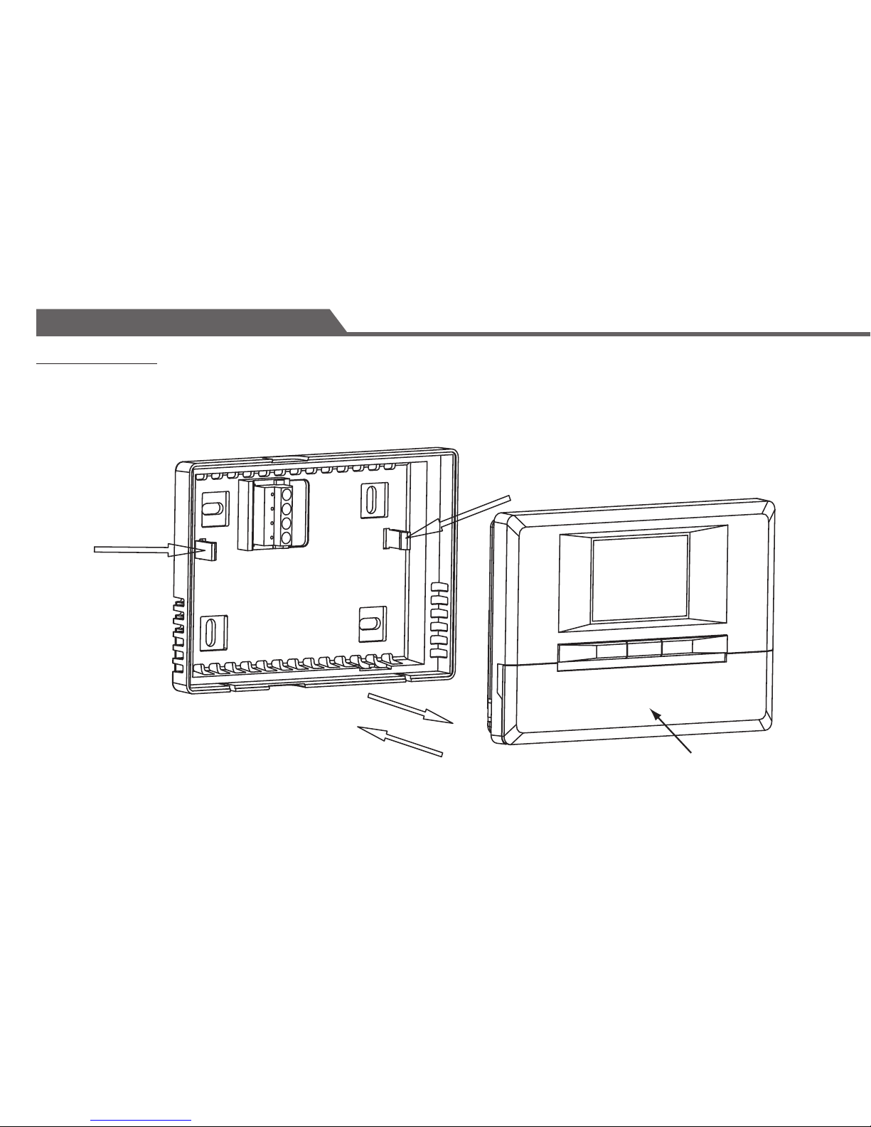
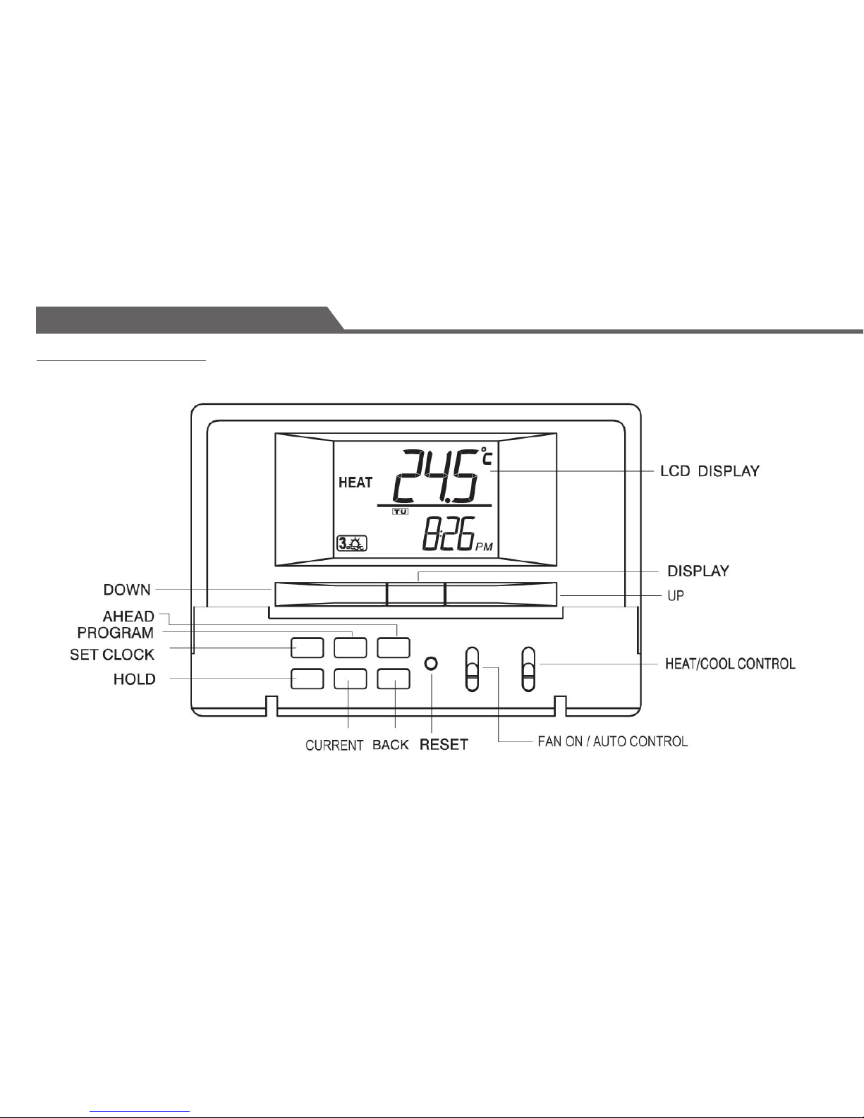
• The time and day must be set before use. Flip the cover to access the function keys and switches.
Features
Cover
Page 6
5
Compatibility
Generally, equipment with low voltage control is compatible with the thermostat.
For details on compatibility of your particular equipment, please call our technical assistance line.
HEATING/COOLING SYSTEMS COMPATIBILTY
Gas – Standing Pilot
•
Gas – Electronic Ignition
•
Gas – Fire Boiler Some Models
Gas – Millivolt System
•
Oil – Fire Burners Some Models
Oil – Fire Furnace
•
Electric Furnace
•
Electric Air Conditioner
•
Baseboard Electric Heater (120/240V)
Heat Pump / Multi-Stage equipment
• NOT COMPATIBLE WITH ANY 120/240 VOLT CIRCUIT
Features
Page 7

6
Introduction
This thermostat can replace common residential thermostats and it is designed for use with most electric, oil or gas
heating and air-conditioning systems that use low voltage control. Please see compatibility chart for more details.
• 4 weekday programs and 4 weekend programs.
• Display temperature with 0.1º resolution.
• Only two AA size batteries (not included) required.
• Built-in protection timing for the air-conditioner compressor.
If you have questions concerning the installation or programming of the thermostat, please call 1-800-265-1833 for
our technical assistance.
Tools required for installation:
• Flathead screwdriver
• Masking tape
• Wire stripper/cutter
• Power drill with a 3/16" bit
• Level
• 2 x AA batteries (sold separately)
Installation
Page 8

7
Choosing Location for the New Thermostat
Thermostat should be mounted:
• Approximately 5 ft (1.5m) from oor.
• Near or in a frequently used room, preferably on an inside partitioning wall.
• On a section of wall without pipes or duct-work.
Thermostat should NOT be mounted:
• Near a window, on an outside wall, or next to a door leading outside.
• With exposure to direct light or heat from a lamp, sun, replace, or other temperature-radiating objects which
may cause false readings.
• Near or in direct airow from supply registers and return-air grills.
• Near concealed pipes and chimneys.
• In areas with poor air circulation, such as behind a door or in an alcove.
After choosing a location for the new thermostat, you must arrange to have a heating contractor install the
control wiring for you.
Installation
TO AVOID FIRE, SHOCK OR DEATH, SHUT OFF POWER
SUPPLY AT THE CIRCUIT BREAKER OR FUSE AND TEST
THAT THE POWER IS OFF BEFORE WIRING.
Page 9
8
Replacing Old Thermostat
Note: Do not operate the cooling system when outside temperature is below 10ºC (50ºF) to avoid damaging the
compressor.
• Test the system to make sure that your heating and cooling are working properly before installation. If either
does not work, contact your local heating/air-conditioning dealer to x the problem before installation.
• TURN OFF POWER to system at the furnace, or at the fuse/circuit breaker panel.
• Carefully unpack your new thermostat and mounting plate; save packaging of screws, instructions and receipt.
• Remove cover from old thermostat. If it does not snap off when pulled rmly from the bottom, check for a
screw used to secure the cover.
• Loosen screws holding thermostat to the wall and lift away the thermostat.
• Disconnect wires from old thermostat or sub-base. As you disconnect each wire, use masking tape to label them
with the old terminal designation. If there are only two wires, they don’t need to be labeled.
• If there is an extra wire that is not connected to your old thermostat, then you won’t need to connect it to the
new thermostat.
• Take care not to let the wires fall back into the wall or let the ends of the wires touch one another.
• The wires are usually designated 'W', 'Y', 'G', 'RH', 'RC', 'O', 'B', 'H1', 'H2'.
Installation
Page 10
9
Installation
Mounting the Thermostat Back-cover
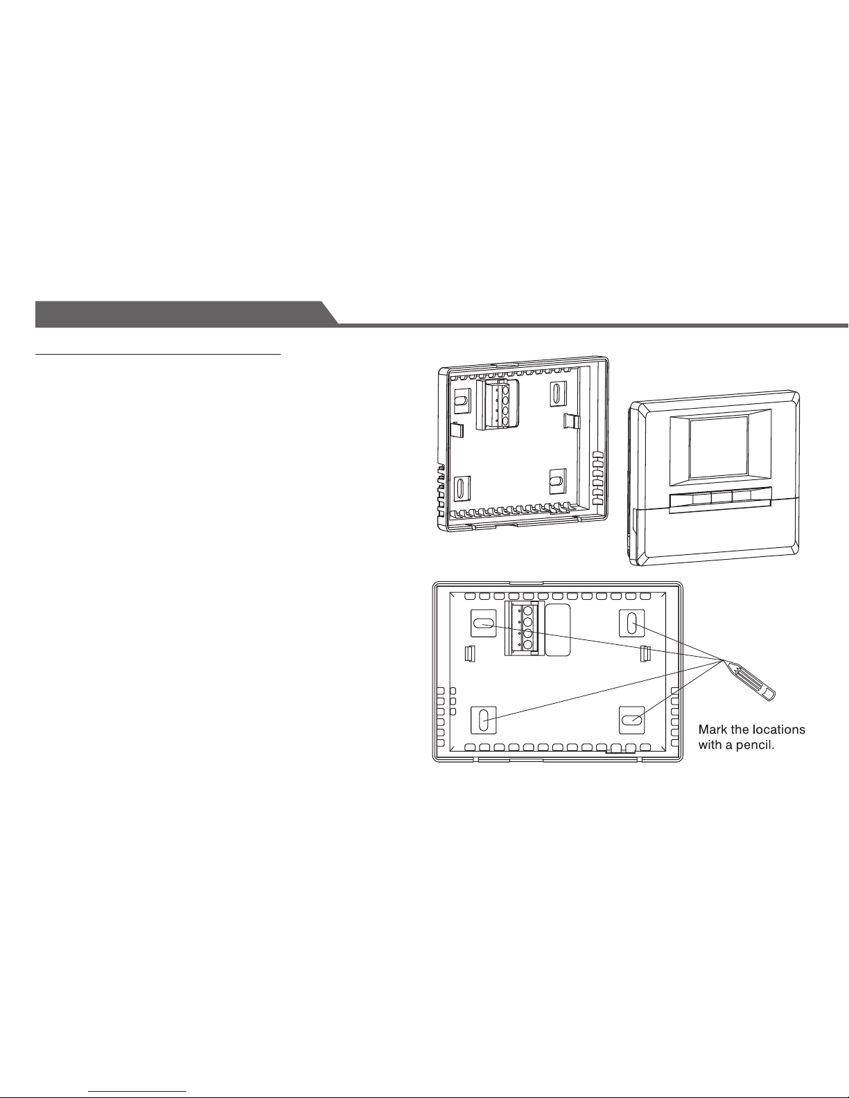
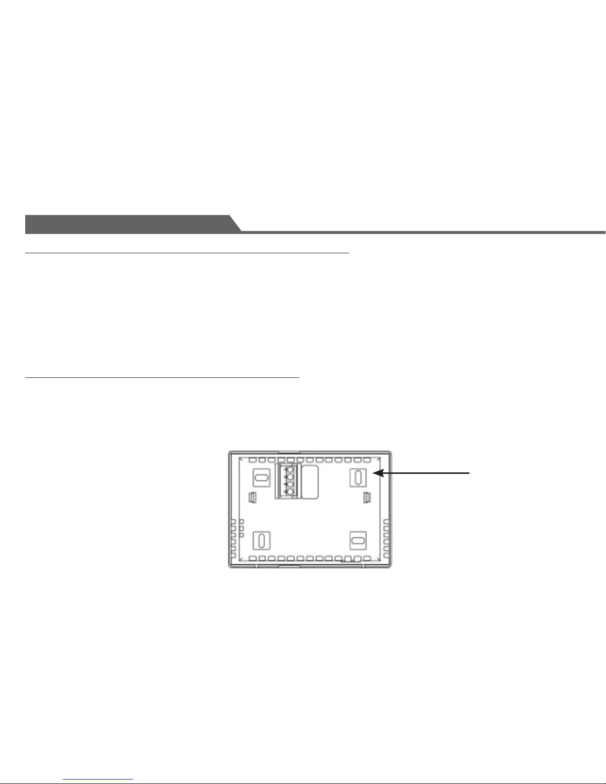
• The back-cover should be mounted horizontally with the
terminals on the left side.
• Thread the existing wiring through the big center hole
from the back and set the back-cover horizontally on the
wall.
• Select two appropriate mounting holes and mark the
locations with a pencil. If necessary, use a level to
make sure the thermostat is leveled.
• Remove the back-cover from the wall and drill two 3/16
inch holes in the marked screw positions. Insert the
wall-anchors into the holes completely. If necessary,
use a hammer to tap-in lightly.
• Mount the back-cover with the two screws to the wall.
Make sure the metal terminals are on the left side.
Page 11
10
Connecting the Wires to the Terminals
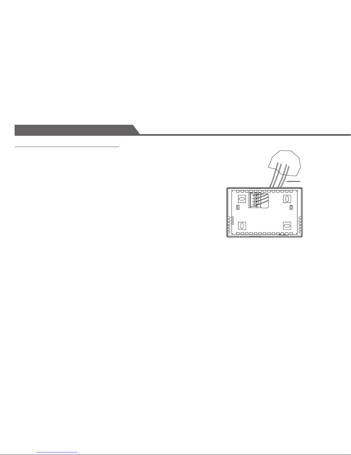
Connect the previously labeled wires to the corresponding terminals,
matching the designations.
Use a screwdriver to securely fasten the wires onto the terminals. Make
sure the wires do not short-circuit with other terminals.
• Depending on your heating/cooling equipment, you may need to connect
2 to 5 wires to the thermostat.
• If your old thermostat has a ‘C’ wire. Please wrap it with electrician’s
tape as it is not used with this thermostat.
• If you have both an ‘Rh’ and ‘Rc’ wires, you may connect them together to
the ‘R’ terminal of thermostat.
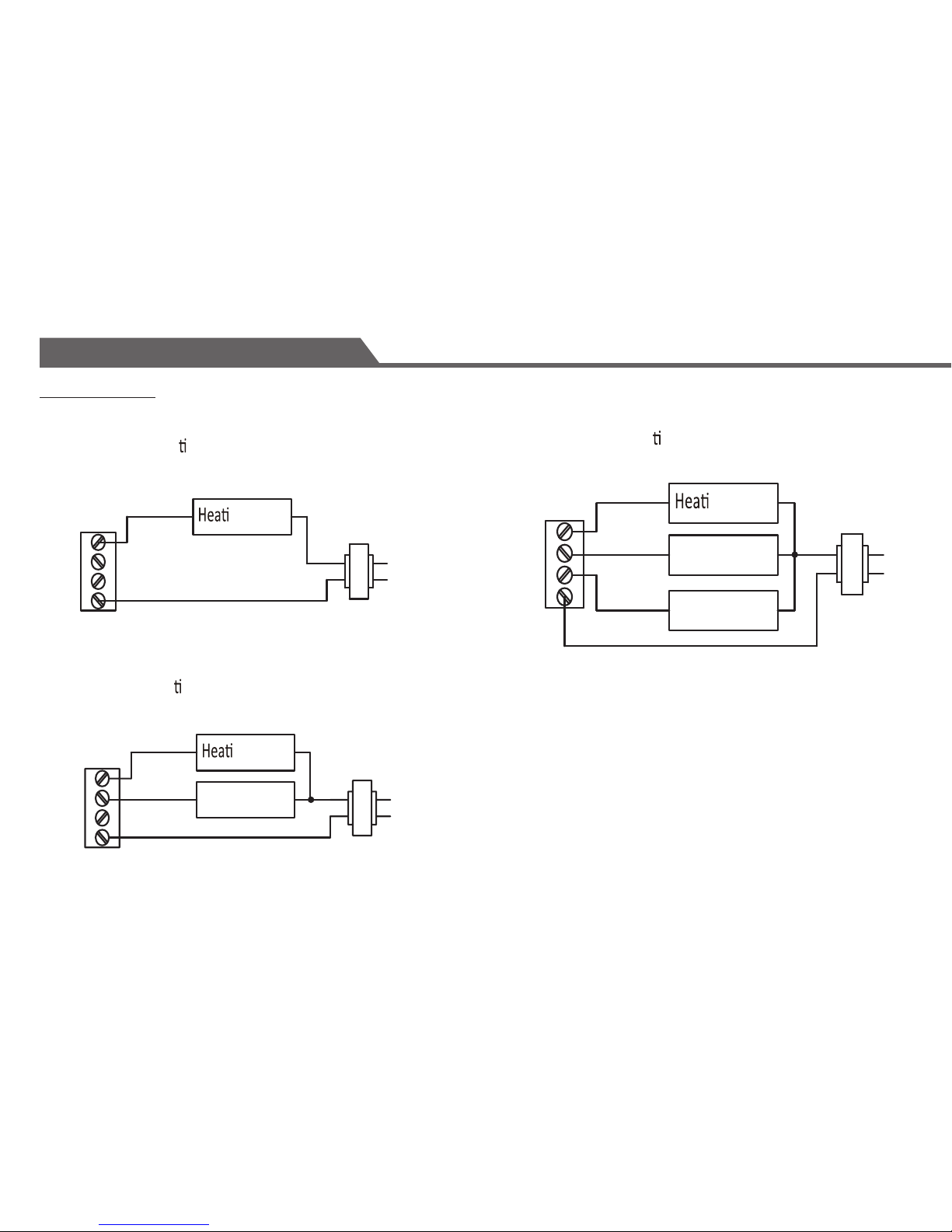
• If you are unsure of the connections, or for new installation, you may refer
to the wiring diagrams on the next page.
Installation
hole in wall
Wires
Page 12
11
Wiring Diagram
Installation
2-wire hea ng
W
G
Y
R
ng Relay
ng
Relay
3-wire hea ng
Fan Relay
W
G
Y
R
4-wire hea ng/cooling
ng Relay
Cooling
Relay
Fan Relay
W
G
Y
R
Page 13
12
Setting the Fan Operation Jumper
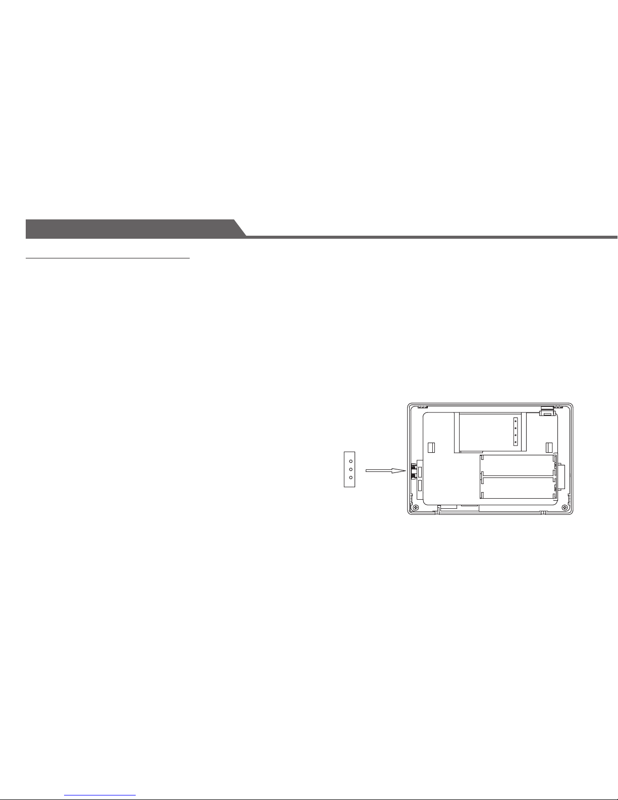
Depending on your home’s heating system, you may need to change the jumper setting for the fan operation.
The jumper is located at the lower left-hand side of the back of the thermostat.
HG - Use this setting for gas or oil-fired furnaces.
This setting allows the fan operation to be controlled by the heating system; not the thermostat.
This is the correct setting for most systems.
HE - Use this setting for electric heating systems.
With this setting, the thermostat will turn on the fan immediately with the heating system.
The jumper is pre-installed in the ‘HG’ position as a factory default.
So there is no need to change the jumper if this is the correct setting.
To change the jumper setting, pull out the small black rectangular block
and align it to the new position and push it in fully.
Installation
HG
W
G
Y
R
HE
HG
HE
W
G
Y
R
Page 14
13
INSTALLING THE BATTERY AND SELECTION OF ºC / ºF DISPLAY
Install the two AA size batteries (not included) to the thermostat following the polarity as marked. The LCD display
will show the room temperature flashing in Celsius. Press UP or DOWN to change the temperature display between
ºC and ºF.
Press DISPLAY or wait for 16 seconds, and the thermostat would go to its normal display, showing Monday 9:00 A.M.
Note: This is a one-time process. The temperature unit of the thermostat CANNOT be changed afterwards unless you
reset the thermostat.
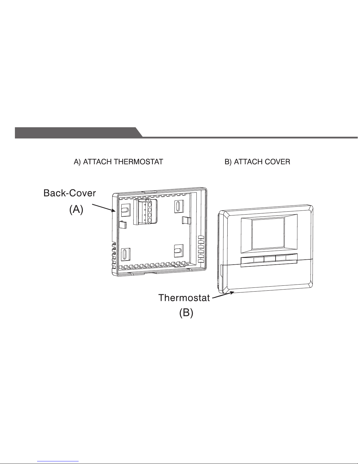
ATTACHING THE THERMOSTAT TO THE BACK-COVER
Line up the front face of the thermostat squarely to the mounted back plate and press it rmly in place.
The thermostat should snap be closed and there should not be any signicant gaps or looseness between the front
face and the back-cover.
Congratulations! You have completed the installation of the thermostat. Please refer to the programming and
operating instructions.
Installation
BACK COVER
Page 15
14
Installation
Page 16
15
Function Key Description
Operation
Page 17
16
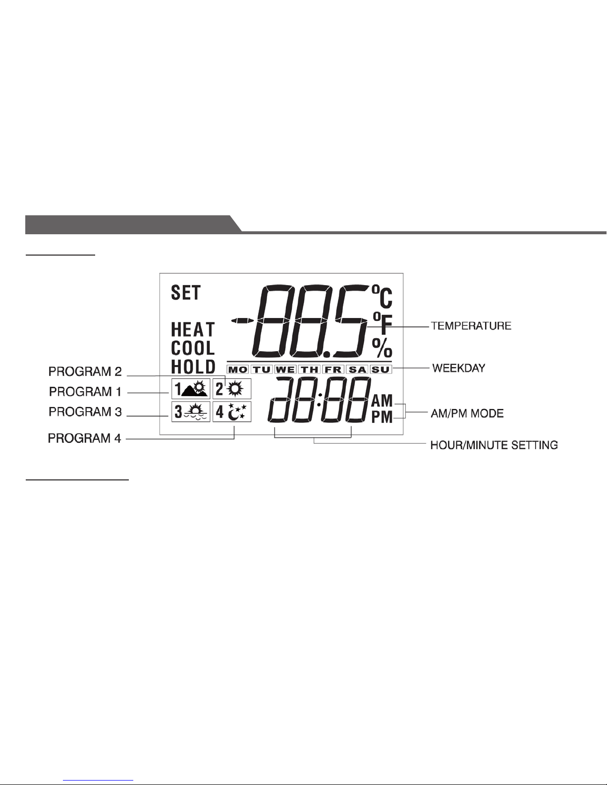
LCD Display
Set Time and Date
•
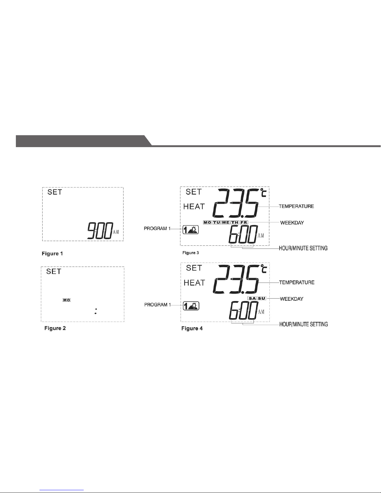
Press SET CLOCK to start time setting. Only time will be shown. (See Figure 1 on page 20)
•
Use AHEAD or BACK to set the current time.
•
Press SET CLOCK again. Weekday will be shown. (See Figure 2 on page 20).
•
Use AHEAD or BACK to set the current day.
•
Press SET CLOCK again to exit.
Operation
Page 18
17
Introduction
This thermostat is equipped with separate programming for weekdays and weekends, with four programs each. This
thermostat is pre-programmed for your convenience or you can set your own programs as desired.
PROGRAM1: MORNING This is typically for the morning when you may prefer a
warmer temperature.
PROGRAM2: DAY This is an energy-savings mode for the time you are away from home.
The setting can be adjusted to minimize energy consumption.
PROGRAM3: EVENING This is for the time you return home and want the house at a comfortable
temperature, typically warmer settings during winter and cooler settings
during summer.
PROGRAM4: NIGHT This is a sleep mode. You may choose to set temperature for energy
savings or comfort as desired.
NOTE:
• The 4 programs for weekdays and the 4 programs for weekends are independent.
You may set them to the same or different time/temperature combination.
• Heating and Cooling modes have separate programs.
Programming
Page 19
18
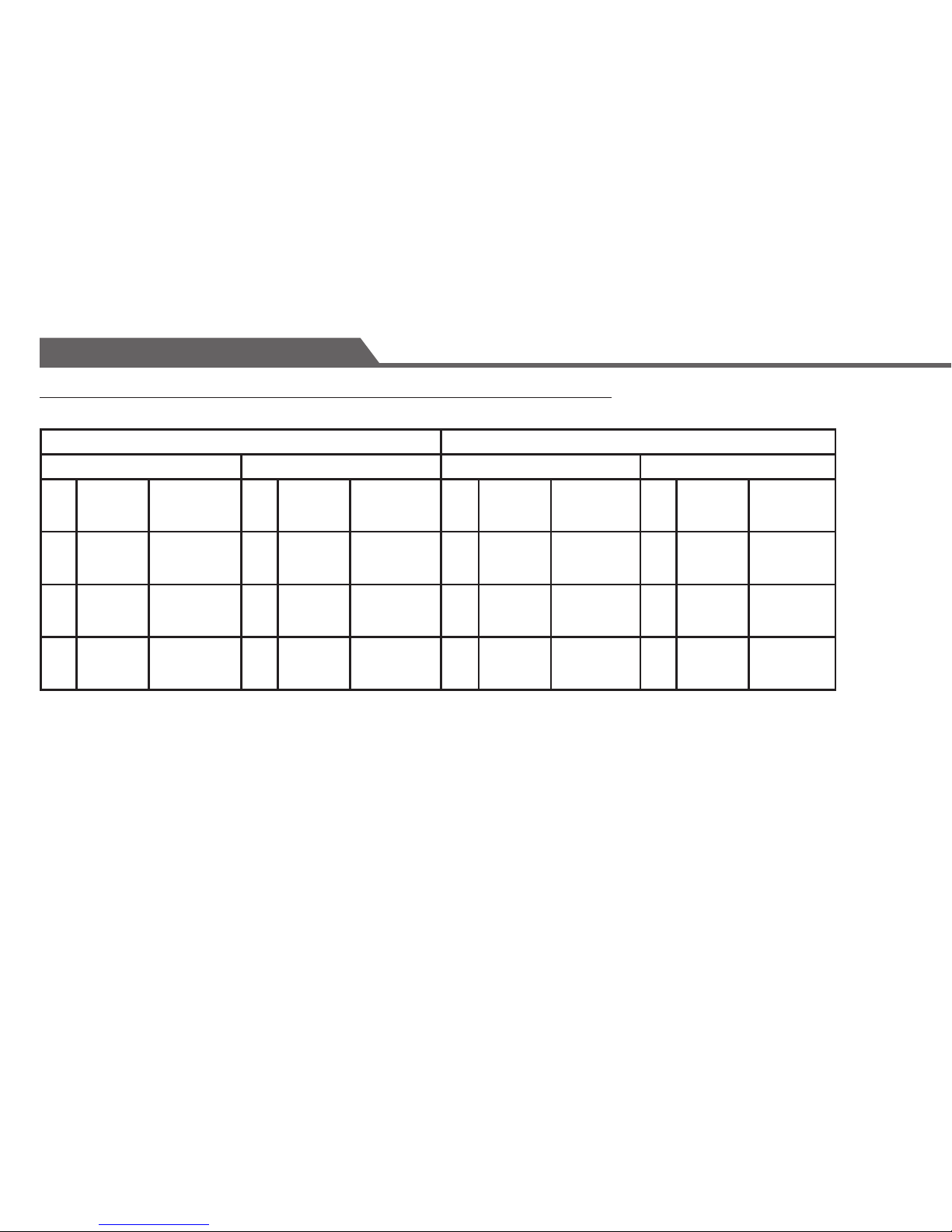
Below is a Schedule of the Pre-programmed Time and Temperature Settings:
HEAT COOL
WEEKDAY WEEKEND WEEKDAY WEEKEND
P1
20.5ºC
(69ºF)
6:00a.m. P1
20.5ºC
(69ºF)
6:00a.m. P1
25ºC
(77ºF)
6:00a.m. P1
25ºC
(77ºF)
6:00a.m.
P2
17.5ºC
(63.5ºF)
8:00a.m. P2
17.5ºC
(63.5ºF)
8:00a.m. P2
29ºC
(84ºF)
8:00a.m. P2
29ºC
(84ºF)
8:00a.m.
P3
21ºC
(70ºF)
5:00p.m. P3
21ºC
(70ºF)
5:00p.m. P3
25ºC
(77ºF)
5:00p.m. P3
25ºC
(77ºF)
5:00p.m.
P4
17ºC
(62.5ºF)
10:00p.m. P4
17ºC
(62.5ºF)
10:00p.m. P4
26ºC
(79ºF)
10:00p.m. P4
26ºC
(79ºF)
10:00p.m.
Programming
Page 20
19
Heating Program
1 - Slide the system switch to the HEAT position and press the PROG key once. The P1 and SET symbol will
appear on the display. MO to FR symbol is shown indicating weekday program is being displayed.
(See figure 3 on page 20).
2 - Use AHEAD or BACK to select the desired start time for weekday program 1.
3 - Use UP or DOWN to set the desired temperature.
4 - Temperature can be set in increments of 0.5º.
5 - Program time can be set in increments of 10 minutes.
6 - After setting correct time and temperature for program 1, press PROG again to display weekday program 2.
Repeat steps 2-5 for weekday programs (P2, P3 and P4) for Saturday and Sunday programming. Use same
method to set the desired time and temperature for program 2.
7 - Repeat the procedures for weekday program 3 and 4, and weekend programs 1-4. (See figure 4 on page 20).
8 - After complete setting of all 8 programs, press PROGRAM to return to normal display (SET symbol will
disappear). Leaving the thermostat without any keys pressed for 16 seconds while setting will also return the
display to normal.
NOTE:
• The PROGRAM key can also be used anytime to review all the set programs.
• To terminate the programming sequence at anytime, press DISPLAY key.
Programming
Page 21
20
Tip: Press and hold the AHEAD/BACK or UP/DOWN key to change the Numbers quickly.
Programming
Page 22
21
COOLING PROGRAM
Slide the system switch to the COOL position and repeat the programming as per the heating program.
TEMPORARY OVERRIDE
To change the temperature temporarily, press UP or DOWN to set the desired temperature. The thermostat will return
to the regular program at the next scheduled program time.
Note: The thermostat has an automatic delay function to protect the heating and cooling systems from undesired on/
off sequences. Sometimes there will be a delay of several minutes before the thermostat will activate the system.
HOLD FUNCTION
• This feature is to hold the thermostat at a constant temperature and disable all set programs until
released.
• Press HOLD once and use UP or DOWN button to set the desired hold temperature. HOLD symbol
will appear to indicate that the Hold function is active.
• To cancel Hold function, press HOLD again. The HOLD symbol will disappear and the thermostat will
return to the programmed temperature.
Programming
Page 23
22
CHECK PROGRAMS
• Press either UP or DOWN once to check the current programmed temperature setting without
changing it.
You may also use the CURRENT key for this function.
ROOM TEMPERATURE
• Current temperature is displayed on the mid-section of the LCD screen.
FAN CONTROL SWITCH
• For automatic control of the fan, set the Fan ON/AUTO switch to the AUTO position. In cooling, the
fan starts/stops with the cooling equipment. In heating, the fan is controlled by the heating
equipment and usually starts a few minutes after the heating equipment turns on.
• To turn on the fan manually, set the Fan ON/AUTO switch to the ON position, the fan will run
continuously to improve air ventilation. To return to automatic control, set the switch to the AUTO
position.
Programming
Page 24
23
HEAT/COOL CONTROL SWITCH
• If this switch is in the OFF position, both the heating and cooling systems are turned off, and all programs and
settings will be disabled.
• Slide the switch to HEAT or COOL to control the heating or air-conditioning system.
• HEAT will display when the switch is in the HEAT position, and will flash when heating is activated.
• COOL will display when the switch is in the COOL position, and will flash when cooling is activated.
PRE-COMFORT RECOVERY
This thermostat is equipped with a (Pre-Comfort Recovery) system that will activate the heating or cooling in advance
of the actual set program time so that the room will be at the desired temperature at the start of the comfort program
time.
It is normal for the system to be activated earlier (up to ½ hour for heating and one hour for cooling) than the actual
set program time.
12/24 HOUR DISPLAY FORMAT (Under the CLOCK Display Mode)
Press both AHEAD and BACK keys together at the same time to change the time display from 12 hour format to 24
hour format (e.g. 8:00pm / 20:00) and vice versa.
Programming
Page 25
24
CHANGING BATTERIES
When :
1) LCD display flashes, or
2) a Beep sound is heard per hour from the unit
It indicates that the batteries are running low and have to be replaced immediately.
However, it is recommended that the batteries be replaced every year even if the indicator is not flashing.
To replace batteries:
• Set the thermostat system switch to the OFF position and have the new batteries on-hand.
• Open the thermostat by gently pulling the front of the thermostat away from the backplate.
• Remove the old batteries and install new ones quickly.
• Close the thermostat to its original position.
If new batteries are inserted within 20 seconds of removing the old ones, the existing time and programs will not be
cleared. Otherwise, the display will show 9:00AM and the thermostat will have to be re-programmed.
Programming
Page 26

25
RESET
If the thermostat shows an abnormal display or if you want to clear all existing programs, use a pointed object to
press the 'R' (Reset) key. Time and programs will need to be set again after a Reset.
SPECIFICATIONS
Number of Programs: Weekly 5+2 day programs with 4 programs per day
Temperature display range: 1ºC - 37.5ºC (34ºF - 99.5ºF)
Temperature setting range: 5ºC - 35ºC (41ºF - 95ºF)
Storage temperature range: -20ºC - 50ºC (-4ºF - 122ºF)
Battery: 2 X AA size batteries (not included)
Programming
Page 27
26
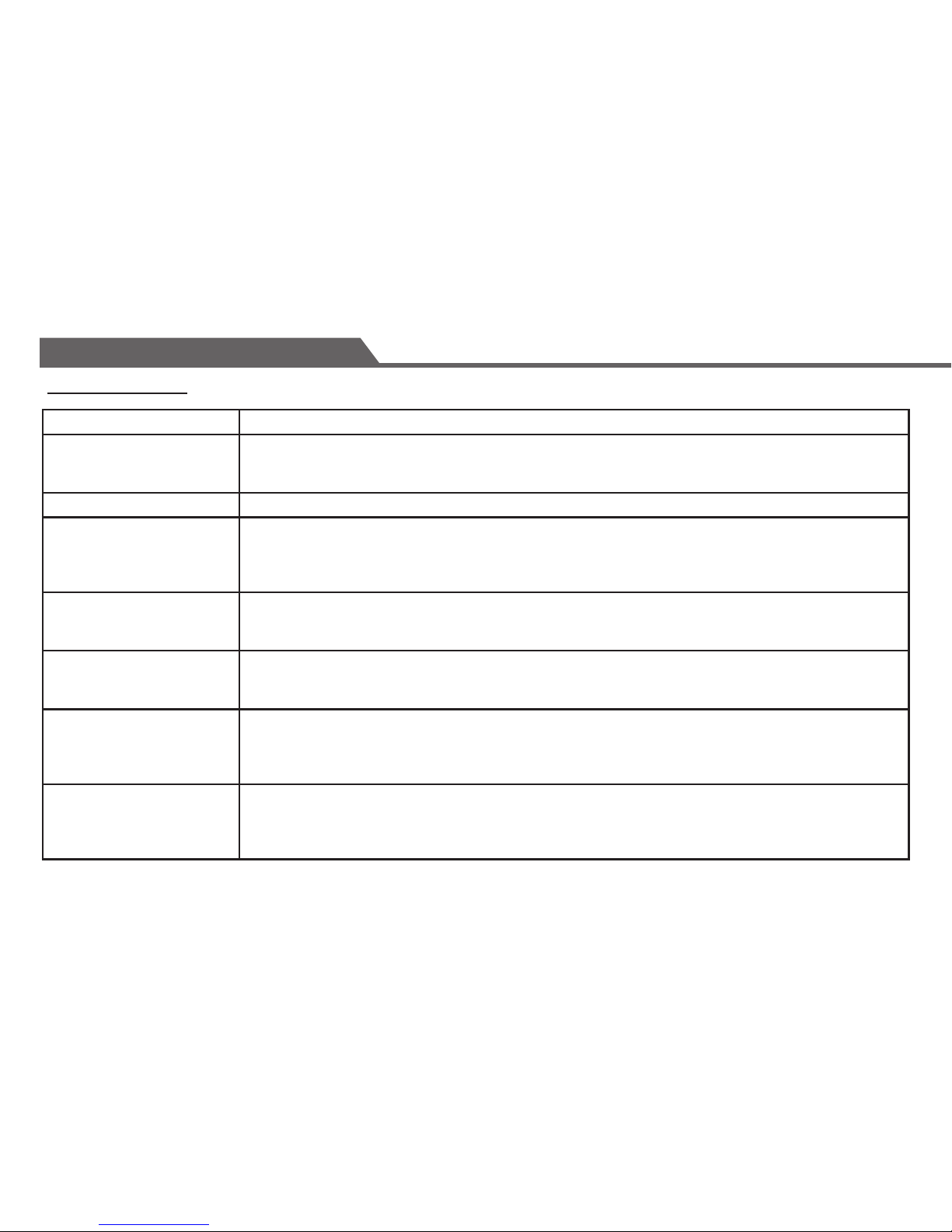
Problem Solution
Display will not come on. • Check if the batteries are installed correctly.
• Check and see if batteries are fresh and the correct size.
• Press the R (reset) button.
Entire display ashes. • Batteries are low. Replace with fresh batteries
Air-conditioning will not
come on (COOL symbol
NOT ashing).
• System switch is in the HEAT or OFF position.
• Current temperature is lower than set temperature. Press CURRENT to check current program.
• Air-conditioning has been turned off within 5 minuted and automatic delay has been
activated to protect the compressor.
Air-conditioning will not
come on (COOL symbol
ashing).
• Check if the air-conditioning main switch is on; it may have been turned off.
Heating will not come
on (HEAT symbol NOT
ashing).
• System switch is in the COOL or OFF position.
• Current temperature is higher than the set temperature. Press CURRENT to check
current program.
Heating will not come on
(HEAT symbol ashing).
• Check if the furnace switch and/or pilot ame is turned on; it may have been turned off.
• Allow some time for the heater to heat up and the fan to activate. Most heaters
will heat up the system for a short while before warm air can be vntilated by the fan.
• HE/HG jumper inside the thermostat is not set correctly. Check installation manual.
The current temperature
is different from the
scheduled temperature.
• It is common for the setting and the displayed temperature to differ occasionally.
The thermostat will be activated if this difference persists.
• There is a temporary override by the user.
• The sysytem is on HOLD. Press HOLD once to resume normal setting.
Supplementary Information
Troubleshooting
Page 28
27
Supplementary Information
Limited Two-year Repair Warranty
This product carries a two-year manufacturer's warranty against defects in workmanship and materials.
This product is not guaranteed against wear or breakage due to misuse and/or abuse.
If the product is defective, return it with a dated proof of purchase, to the retailer from which you purchased it.
NOT COMPATIBLE WITH ANY 120/240 VOLT CIRCUIT.
CONTROL by/par Canarm™
Customer Service number (English) 1-800-265-1833
Numéro du Service à la Clientèle de Canarm (Français) 1-800-567-2513
Made in China
Imported by/Importé par
CONTROL™ by Canarm, CANARM Ltd/ltée.,
2157 Parkedale Avenue, Brockville, Ontario K6V 5V6
www.canarm.com
© 2012 Kelan-Hudson Group Inc.
Product specifications and appearance are subject to change without notice.
 Loading...