

Page 1

M–T raverse
User Manual
0001-0122
Revision F
i
Page 2

Technical Assistance
If you have comments or questions concerning the operation of the M–Traverse, a member of
our Technical Support Staff will be happy to assist you. Ask for Technical Support:
(763) 424-7800 or (800) 342-4411
Copyright © 1996 Contrex
ii
Contrex
®
8900 Zachary Lane North
Maple Grove, Minnesota 55369
Page 3

DANGER
Improper installation
or improper operation
of this motion control unit
can cause severe injury, death or
damage your system.
Integrate this motion control unit
into your system
with caution.
Comply with the National
Electrical Code
and all applicable local
and national codes.
Page 4

Table of Contents
Introduction 1-1
Introducing the M–Traverse........................................................................... 1-3
Examples of M–Traverse Applications .......................................................... 1-4
Installation / Setup 2-1
Configuration.................................................................................................. 2-3
Mounting ........................................................................................................ 2-7
Wiring ............................................................................................................. 2-9
Inputs.................................................................................................. 2-10
Outputs............................................................................................... 2-19
Serial Communications ...................................................................... 2-24
Calibration.................................................................................................... 2-27
Motor Drive Set Up............................................................................. 2-29
Encoder Polarity Check ..................................................................... 2-29
M–Traverse Calibration...................................................................... 2-30
Operation3-1
Keypad Operation.......................................................................................... 3-3
Control Parameters........................................................................................ 3-7
Follower Mode...................................................................................... 3-8
Direct Mode........................................................................................ 3-29
Jog...................................................................................................... 3-30
Tuning ................................................................................................. 3-32
Output Control.................................................................................... 3-34
M–Traverse Operation................................................................................. 3-43
Follower Mode.................................................................................... 3-44
Home Set ........................................................................................... 3-45
Home Seek......................................................................................... 3-45
Home Return...................................................................................... 3-50
Direct Mode........................................................................................ 3-51
Jog...................................................................................................... 3-52
i
Page 5

Monitor Variables ......................................................................................... 3-53
Input Monitoring ................................................................................. 3-54
Output Monitoring............................................................................... 3-56
Performance Monitoring..................................................................... 3-58
Status Monitoring ............................................................................... 3-60
Serial Communications................................................................................ 3-63
Using Serial Communications............................................................ 3-64
Communications Software Design..................................................... 3-66
Troubleshooting 4-1
Diagnostics .................................................................................................... 4-3
Troubleshooting ........................................................................................... 4-13
EPROM Chip Replacement ......................................................................... 4-19
References 5-1
Glossary......................................................................................................... 5-3
Appendix A: M–Traverse Specifications ..................................................... 5-11
Appendix B: Formulas ................................................................................ 5-13
Appendix C: Parameter Summary - Numeric Quick Reference ................. 5-14
Appendix D: Control Parameter Reference................................................ 5-36
Appendix E: Monitor Variable Reference.................................................... 5-38
Appendix F: Fax Cover Sheet .................................................................... 5-39
Appendix G: Wiring Diagram Examples ..................................................... 5-40
Appendix H: Revision Log .......................................................................... 5-44
Service policy............................................................................................... 5-45
Warranty....................................................................................................... 5-46
Index ............................................................................................................ 5-47
ii
Page 6

List of Illustrations
Figure 1-1 M–Traverse Level Wind Application ........................................ 1-4
Figure 1-2 M–Traverse Web Scanning Application.................................... 1-5
Figure 2-1 Rear View of M–Traverse ........................................................ 2-3
Figure 2-2 Power Board / Isolator Jumper ................................................ 2-4
Figure 2-3 Power Board / SW1 Switch ...................................................... 2-5
Figure 2-4 M–Traverse Mounting and Cutout Dimensions ....................... 2-6
Figure 2-5 M–Traverse General Wiring Schematic ................................... 2-8
Figure 2-6 Input Power............................................................................. 2-10
Figure 2-7 Lead frequency ...................................................................... 2-10
Figure 2-8 Feedback frequency .............................................................. 2-11
Figure 2-9 Home Sync ............................................................................. 2-11
Figure 2-10 Setpoint Select A .................................................................... 2-12
Figure 2-11 Setpoint Select B .................................................................... 2-12
Figure 2-12 Home Set ................................................................................ 2-13
Figure 2-13 Home Seek ............................................................................. 2-13
Figure 2-14 Home Return........................................................................... 2-14
Figure 2-15 Batch Reset ............................................................................ 2-14
Figure 2-16 Run ......................................................................................... 2-15
Figure 2-17 Wait......................................................................................... 2-15
Figure 2-18 F-Stop ..................................................................................... 2-16
Figure 2-19 Keypad Lockout ..................................................................... 2-16
Figure 2-20 Forward Limit .......................................................................... 2-17
Figure 2-21 Reverse Limit ......................................................................... 2-17
Figure 2-22 Jog Forward/Reverse ............................................................. 2-18
Figure 2-23 Jog ......................................................................................... 2-18
Figure 2-24 Speed Command Out ............................................................2-19
Figure 2-25 Discrete Outputs ..................................................................... 2-23
Figure 2-26 M-Traverse Multidrop Installation .......................................... 2-24
Figure 2-27 M-Traverse Serial Communications Connections .................. 2-25
Figure 2-28 Location of M-Traverse Scale and Zero Pot........................... 2-28
Figure 3-1 M–Traverse Front Panel .......................................................... 3-5
Figure 3-2 M–Traverse Internal Structure ............................................... 3-58
Figure 4-1 Motor Does Not Stop Flowchart ............................................ 4-14
iii
Page 7

Figure 4-2 Motor Does Not Run Flowchart ............................................. 4-15
Figure 4-3 Motor Runs at Wrong Speed Flowchart ................................ 4-16
Figure 4-4 Motor Runs Unstable Flowchart ............................................ 4-17
Figure 4-5 EPROM Location ................................................................... 4-18
Figure G-1 M–Traverse Wiring Connections without Relays .................. 5-40
Figure G-2 Relay Run/Stop Wiring Connections .................................... 5-41
Figure G-3 Run/Stop for Regen with Armature Contactor ...................... 5-42
Figure G-4 Run/Stop for Non-Regen with Armature Contactor .............. 5-43
iv
Page 8

List of Tables
Table 3-1 Basic Keypad Entry ................................................................. 3-4
Table 3-2 Default Control Mode Control Parameters .............................. 3-9
Table 3-3 Entering Control Mode Control Parameters ............................ 3-9
Table 3-4 Default Follower Scaling Control Parameters ....................... 3-11
Table 3-5 Entering Follower Scaling Control Parameters ..................... 3-12
Table 3-6 Default Setpoint Control Parameters ..................................... 3-13
Table 3-7 Entering Setpoint Control Parameters ................................... 3-14
Table 3-8 Default Traverse Length Control Parameters ........................ 3-15
Table 3-9 Entering Traverse Length Control Parameters ...................... 3-15
Table 3-10 Default Accel/Decel Length Control Parameters ................... 3-17
Table 3-11 Entering Accel/Decel Length Control Parameters ................. 3-17
Table 3-12 Default Dwell Control Parameters ......................................... 3-18
Table 3-13 Entering Dwell Control Parameters ...................................... 3-18
Table 3-14 Default Control Parameters for Changes .............................. 3-23
Table 3-15 Entering Control Parameters for Changes ............................ 3-23
Table 3-16 Default Resume Enable Control Parameter .......................... 3-25
Table 3-17 Entering Resume Enable Control Parameter ........................ 3-25
Table 3-18 Default Polarity Control Parameters ...................................... 3-27
Table 3-19 Entering Polarity Control Parameters .................................... 3-27
Table 3-20 Default Direct Mode Control Parameters ............................... 3-28
Table 3-21 Entering Polarity Control Parameters ................................... 3-28
Table 3-22 Default Direct Mode Control Parameters ............................... 3-29
Table 3-23 Entering Direct Mode Control Parameters ............................. 3-29
Table 3-24 Default Jog Control Parameters ............................................ 3-30
Table 3-25 Entering Jog Control Parameters .......................................... 3-30
Table 3-26 Default Tuning Control Parameters ....................................... 3-32
Table 3-27 Entering Tuning Control Parameters ..................................... 3-33
Table 3-28 Default Batch Control Parameters .........................................3-35
Table 3-29 Entering Batch Control Parameters ....................................... 3-35
Table 3-30 Default Alarm Control Parameter ........................................... 3-36
Table 3-31 Entering Alarm Control Parameter ......................................... 3-36
Table 3-32 Default At-Home Control Parameter ...................................... 3-37
Table 3-33 Entering At-Home Control Parameter .................................... 3-37
v
Page 9

Table 3-34 Default Control Parameters for Output A ............................... 3-39
Table 3-35 Entering Control Parameters for Output A ............................. 3-39
Table 3-36 Default Control Parameters for Output B ............................... 3-41
Table 3-37 Entering Control Parameters for Output B ............................ 3-41
Table 3-38 Parameter Send - Host Transmission..................................... 3-67
Table 3-39 Parameter Send - M–Traverse Response ............................. 3-69
Table 3-40 Control Command Send - Host Transmission ....................... 3-71
Table 3-41 Control Command Send - M–Traverse Response ................. 3-73
Table 3-42 Data Inquiry - Host Transmission ........................................... 3-75
Table 3-43 Data Inquiry - M–Traverse Response .................................... 3-77
Table 3-44 ASCII to Binary ...................................................................... 3-79
Table 3-45 Binary Monitor Parameters .................................................... 3-80
vi
Page 10

Introduction
Introducing the M–Traverse
Examples of M–Traverse Applications
1-1
Page 11

1-2
Page 12

INTRODUCING THE M–TRAVERSE
The M–Traverse is a highly accurate, digital, position controller. The M–Traverse's
technically advanced, internally embedded, control software is specifically designed for
the precise control of reciprocating lead/follower motion applications. These
applications are characterized by symmetric forward and reverse follower profiles. The
M–Traverse is often used for level winding, web scanning and fabric lapping, however it
can be used in any operation that requires symmetrical follower profiling against a lead.
The M-Traverse allows you to enter information that is unique to your system's
operation through user friendly Control Parameters. The M–Traverse uses this
information to calculate and determine a variety of controls and functions and frees you
from complex computations. When your system is engaged (Run), the traversing
mechanism (Follower) accelerates from the “Home” position to the preset laypitch
(Setpoint). Operating at the laypitch, the traverse mechanism can precisely align a
product on a reel or web then decelerate the traversing mechanism to the end of the
Traverse Length before beginning the end Dwell. At the “Dwell,” the M-Traverse
assures that the product is properly aligned before returning in the opposite direction.
The M–Traverse is remarkably precise - within one encoder line.
The M–Traverse accepts up to four preset pairs of “Setpoint” and “Traverse Length”
parameters. These parameters can be engaged with a quick flip of a switch during a
product change over. The M-Traverse features additional advanced control that
includes; profile definition that uses engineering unit parameters, dynamic profile
redefinition during a run, automatic profile generation, batch counting, unipolar/bipolar
drive compatibility and dynamic system monitoring. There are seven discrete outputs
for external control integration, which includes two user specified profile position
outputs.
Although the M–Traverse has many advanced control capabilities, it is easy to use. The
integrated keypad and display make access to the control and monitor parameters both
direct and simple. A “Keypad Lockout” function allows you to restrict access to the
control parameters after you have completed the setup process.
The M–Traverse features dedicated short-cut keys for quick access to the “Setpoint,”
“Batch Count,” “Tach,” and “Status” parameters. In addition to the integrated user
keypad and display, the M–Traverse has a RS-422 serial communications port through
which you can gain computer access to all of the control and monitor parameters.
Integrating the M–Traverse's applied intelligence with your system puts precise control
and perfect synchronization at your fingertips, quickly, easily and cost effectively.
1-3
Page 13

EXAMPLES OF M–TRAVERSE
APPLICATIONS
The Level Wind is one of the M–Traverse's principle applications. The Level Wind
application uses the Lay Adjusted option in the Follower mode of operation. In a Level
Wind application, the M–Traverse locates the start or “Home” position and accelerates
the traversing mechanism (Follower) to the preset laypitch (Setpoint). The traversing
mechanism feeds a web product such as a wire, fiber optic cable or tape, onto the
rotating reel (Lead) at this laypitch then decelerates the traversing mechanism to the
end of the Traverse Length. At the “Dwell,” the M-Traverse assures that the web
material is properly aligned on the reel before returning in the opposite direction.
Figure 1-1 illustrates a typical Level Wind application.
HOME SYNC
FOLLOWER
DIRECTION
OF WIND
FEEDBACK FREQUENCY
LEAD
Cut
Position
Length
Batch
Status
Count
9
7
8
45
6
23
1
0
Alt
Enter
Clear
M-TRAVERSE
M–Traverse
CONTREX
LEAD FREQUENCY
1-4
Figure 1-1 M–Traverse Level Wind Application
Page 14

Web Scanning is another common M–Traverse application. The Web Scanning
application frequently uses the Standard option in the Follower mode of operation,
however, there are applications for which Web Scanning may use the Lay Adjusted
option in the Follower mode of operation. The M–Traverse locates the start or “Home”
position and accelerates the traversing mechanism (Follower) to the preset laypitch
(Setpoint). The traversing mechanism applies a secondary product, such as glue or
reinforcing fiber, onto the moving web. Then the M–Traverse decelerates the traversing
mechanism to zero speed at the end of the “Traverse Length”. At the “Dwell” (which is
usually set at zero) the traversing mechanism reverses its direction and returns with a
symmetric reverse profile. Using zero or very low “Accel / Decel” and “Dwell”
parameters creates a zigzag pattern. Figure 1-2 illustrates a typical Web Scanning
application.
LEAD
HOME SYNC
FOLLOWER
LINE FLOW
FEEDBACK FREQUENCY
Cut
Position
Length
Batch
Status
Count
9
7
8
45
6
23
1
0
Alt
Enter
Clear
M-TRAVERSE
M–Traverse
CONTREX
LEAD FREQUENCY
Figure 1-2 M–Traverse W eb Scanning Application
1-5
Page 15

—NOTES—
1-6
Page 16

Installation / Setup
Configuration
Mounting
Wiring
Inputs
Outputs
Serial Communications
Calibration
Motor Drive Setup
M-Traverse Calibration
2 - 1
Page 17

2 - 2
Page 18

CONFIGURATION
This section will show you how to re-configure the M-Traverse for electrical
compatibility. Complete these procedures prior to installation. These procedures do
not require power to complete.
The two areas that are involved in re-configuring the M-Traverse are the Isolator
Voltage jumper and the Power Voltage switch. Do not re-configure the M-Traverse's
Frequency Input. Use the default Quadrature position.
To re-configure the Isolator Voltage jumper and the Power Voltage switch, remove the
back plate, then carefully remove the Power Board. Figure 2-1 illustrates the location
of the boards.
Power Board CPU Board
Figure 2-1 Rear View of M-Traverse
2 - 3
Page 19
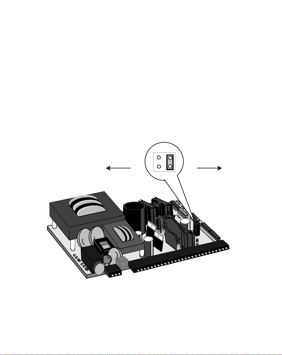
The Isolator Voltage jumper (J3) is located on the Power Board (see Figure 2-2). It
configures the isolated analog output for either voltage that is ranged by an internal +15
volt reference or for voltage that is auto-ranged by the voltage level of the motor drive.
The auto-range voltage position is the default configuration for the Isolator Voltage
jumper.
NOTE: In most cases, the default configuration will be appropriate for your application
and it will not be necessary to re-configure.
If the motor drive does not have an external voltage reference, re-configure the Isolator
Voltage by moving the jumper from the default auto-range voltage position (1) to the
internal +15 volt reference position (2).
Internal Reference
Position
115
J3
2 1
Auto Range
Position (default)
2 - 4
Figure 2-2 Power Board / Isolator Jumper
Page 20
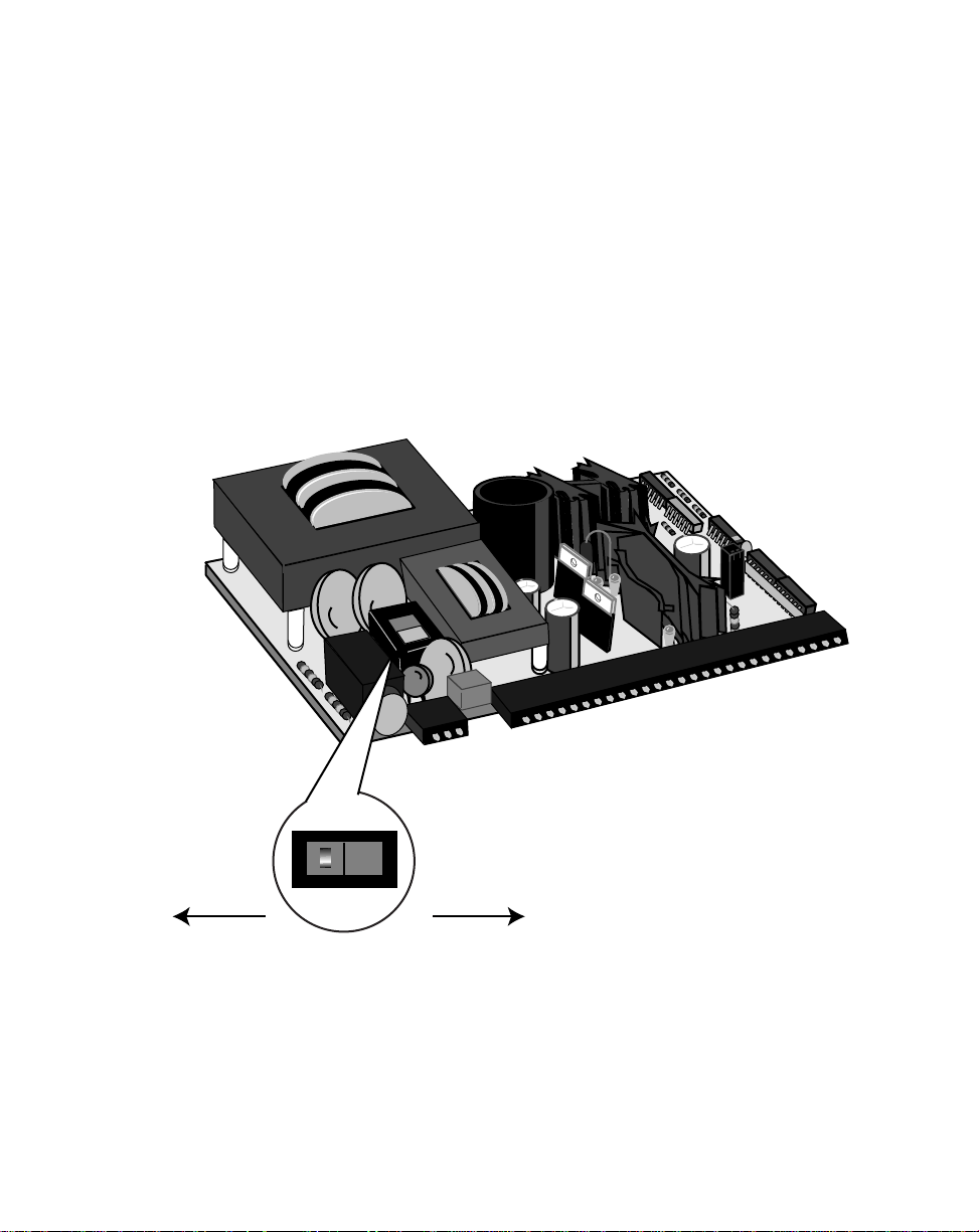
The Power Voltage switch (SW1) is located on the Power Board (see Figure 2-3). The
default configuration for the Power Voltage switch is 115 VAC.
NOTE: In most cases, the default configuration will be appropriate for your application
and it will not be necessary to re-configure.
To re-configure for 230V, move the switch from the 115V position (left) to the 230V
position (right).
115
115V
(default)
115V
230V
Figure 2-3 Power Board / SW1 Switch
2 - 5
Page 21
Set
Contrex
CUTOUT
(
7.25" .03"
CUTOUT
(
3.65" .03"
3.6"
7.2"
)
5.7"
(
DOOR PANEL
Contrex
7.5"
M-TRAVERSE
2 - 6
3.9"
Figure 2-4 M–Traverse Mounting and Cutout Dimensions
Page 22

MOUNTING
This section contains instructions for mounting the M–Traverse in the door panel of a
NEMA Industrial Electrical enclosure. The M–Traverse is packaged in a compact 1/2
DIN Vertical Instrument Enclosure that mounts easily in the door of your Industrial
Electrical Enclosure.
To mount the M–Traverse:
1) The NEMA Industrial Electrical Enclosure that will house the M–
Traverse must conform to the following environmental conditions:
Temperature: 0 - 55 degrees C
(Internal NEMA enclosure temperature)
Humidity: 0 - 90% RH non-condensing
2) The dimensions for the door panel cutout are 3.65"+ .03" X 7.25 +.03"
(see figure 2-4). Allow two inches of clearance on all sides of the
cutout for mounting clamp attachments, wire routing and heat
convection.
3) Insert the M–Traverse through the door panel cutout until the gasket
and bezel are flush with the door panel (see figure 2-4).
4) The mounting clamps can be inserted in the holes that are located
either on the top and bottom or on the sides of the M–Traverse.
Tighten the mounting screws until the M–Traverse is mounted securely
in the NEMA Electrical Enclosure. Do not overtighten.
2 - 7
Page 23
* Power for encoder and prox switches may be supplied by J3, pins 1 or 2.
Total +5 VDC current should not exceed 250 mA
Total +12 VDC current should not exceed 200 mA
J1
+12 V OUT
50 MA MAX
+
TXD–+
RXD
–
COM
+V
SIG
SIO
COM
DRIVE
ENABLE
BATCH
DONE
ALARM
PROFILE
DIRATHOME
OUTPUTAOUTPUT
B
+EXTDCSUPPLY–
RRR
R
D
R
I
V
E
SERIAL COMMUNICATIONS
RS 485
L
E
A
D
F
E
EDB
ACK
J3
CHA
COM
CHB
SHIELD
CHA
COM
CHB
COM
HOME SYNC
STPT SEL A
(C)
COM
STPT SEL B
(C)
HOME SET
J3 (C)J4 COM
HOME
SEEK(C)
HOME
RETURN(C)
COM
BATCH
RESET(C)
RUN(C)
COM
WAIT (O)
F–STOP(O)
COM
KEYPAD
LOCKOUT(C)
FORWARD
LIMIT(C)
COM
REVERSE
LIMIT(C)
FWD(O)
JOG
REV(C)
COM
JOG(C)
SHIELD
J4
+5 V OUT
500 MA MAX
+12 V OUT
150 MA MAX
INPUT VOLTAGE – 115/230 VAC
INPUT CURRENT – 0.25 AMP
INPUT FREQUENCY – 50/60 HZ
J2
USE COPPER WIRE ONLY.
SELECT WIRE SIZE ACCORDING TO AMPACITY
FOR 60/75 C WIRE
TIGHTEN TERMINALS TO 5 IN/LB
120 V
F
US
E
F
US
E
R
R
R
123456789
1011121314151617181920
123
123
+ 12VDC AUX OUT
R
R
RRR
R
DRIVE
+ VDC
SIGNAL
ISO COMMON
DRIVE ENABLE
BATCH DONE
ALARM
PROFILE DIR
AT-HOME
OUTPUT A
OUTPUT B
R
EXT
DC
SUPL
+
–
TXD +
TXD –
RXD +
RXD –
COMMON
RS422
SERIAL
COMM
CHASSIS GND
NEUTRAL / L2
L1
AC
POWER
J1
J2
50 V Max
123456789
101112131415161718
123456789
10111213141516
+ 5VDC AUX OUT
+12VDC AUX OUT
J3
CHA
COM
CHB
SHLD
CHA
COM
CHB
LEAD *QUAD
ENCODER
FEEDBACK
*
QUAD
ENCODER
HOME
*
SYNC
SETPOINT
SELECT A
SETPOINT
SELECT B
HOME SET
HOME SEEK
HOME RETURN
BATCH RESET
RUN
WAIT
F–STOP
KEYPAD LOCKOUT
FORWARD LIMIT
REVERSE LIMIT
JOG FORWARD
/REVERSE
JOG
SHIELD
J4
CHASSIS GND
NEUT/L2
L1
2 - 8
Figure 2-5 M-Traverse General Wiring Schematic
Page 24
WIRING
This section contains the input, output and serial communications wiring information for
the M–Traverse. Please read this section prior to wiring the M–Traverse to ensure that
you make the appropriate wiring decisions.
NOTE: The installation of this motor control must conform to area and local electrical
codes. See
National Fire Protection Association, or
Use local codes as applicable.
Use a minimum wire gauge of 18 AWG.
Use shielded cable to minimize equipment malfunctions from electrical noise
and terminate the shields at the receiving end only.
Keep the AC power wiring (J2) physically separated from all other wiring on
the M–Traverse. Failure to do so could result in additional electrical noise and
cause the M–Traverse to malfunction.
Inductive coils on relay, contactors, solenoids that are on the same AC power
line or housed in the same enclosure should be suppressed with an RC
network across the coil. For the best results, use resistance (r) values of 50
ohms and capacitance (c) values of 0.1 microfarads.
The National Electrical Code
The Canadian Electrical Code
(NEC,) Article 430 published by the
(CEC).
Install an AC line filter or isolation transformer to reduce excessive EMI noise,
such as line notches or spikes, on the AC power line.
DANGER
Hazardous voltages.
Can cause severe injury, death or
damage to the equipment.
The M–Traverse should only be
installed by a qualified
electrician.
2 - 9
Page 25
INPUTS
NOTE: The installation of this motor control must conform to area and local electrical
codes. See
National Fire Protection Association, or
Use local codes as applicable.
Input Power (J2 pins 1, 2, 3)
The M–Traverse operates on either a
115 VAC or 230 VAC (-10% + 15%,
0.25 Amps., 50/60 Hz). Use the
separate 3 pin connector (J2) for the
power connection.
The National Electrical Code
The Canadian Electrical Code
(NEC,) Article 430 published by the
(CEC).
Chassis Gnd
Neutral / L2
1
2
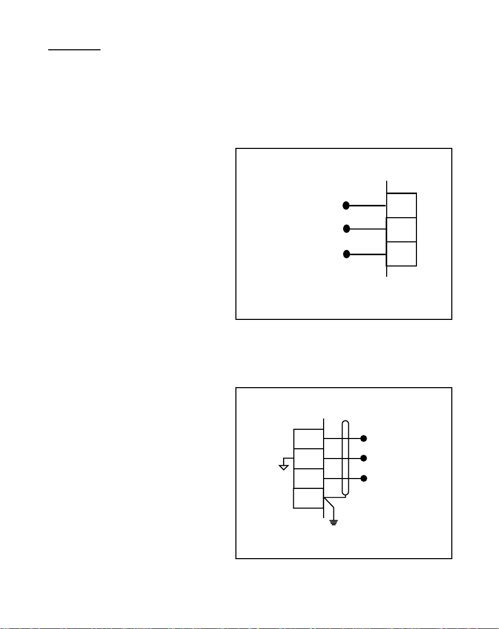
Lead Frequency (J3 pins
3,4,5,6)
The Lead Frequency is a pulse train
input that the M-Traverse uses to
determine the Lead motor's speed
and position. The Lead Frequency
signal must be quadrature. For
signal level specifications, refer to
References: Appendix A
M–Traverse Specifications.
,
L1
Figure 2-6 Input Power
3
4
5
6
J3
CHA
COM
CHB
Shield
3
J2
Lead
Quad
Encoder
2 - 10
Figure 2-7 Lead Frequency
Page 26

Feedback Frequency
(J3 pins 6,7,8,9)
The Feedback Frequency is a pulse
train input that the M-Traverse uses to
determine the Follower motor's speed
and position. The Feedback
Frequency signal must be quadrature.
For signal level specifications, refer to
References: Appendix A, M–T raverse
Specifications.
If the Feedback Frequency is lost,
the M-Traverse will command a !00% Speed Out
and the motor will run at 100% of the calibrated range.
This can cause severe injury, death or
it can damage your equipment.
Home Sync (J3 pins 6,11,12)
Figure 2-8 Feedback Frequency
WARNING
6
7
8
9
J3
Shield
CHA
COM
CHB
Feedback
Quad
Encoder
The Home Sync input identifies the
location of “Home” for the Home Seek
operation. This input is operated by
either a proximity switch or an optical
sensor switch (NPN output).
6
11
12
J3
Shield
Common
Home Sync
Figure 2-9 Home Sync
2 - 11
Page 27

Setpoint Select A
(J3 pins 13,14)
The Setpoint Select A and B inputs
are used in conjunction with each
other to select one of four
M–Traverse setpoints and traverse
lengths. The chart below displays
these four setpoints.
Setpoint Select B
(J3 pins 14,15)
Setpoint Select A
13
14
J3
Figure 2-10 Setpoint Select A
The Setpoint Select A and B inputs
are used in conjunction with each
other to select one of four
M–Traverse setpoints and traverse
lengths. The chart below displays
these four setpoints.
Setpoint Select B
Setpoint Select B
Open
Open
Setpoint Select B
Closed
2 - 12
Figure 2-11 Setpoint Select B
Setpoint Select A
Open
Setpoint 1
Traverse Length 1
Setpoint 3
Traverse Length 3
14
15
J3
Setpoint Select B
Setpoint Select A
Closed
Setpoint 2
Traverse Length 2
Setpoint 4
Traverse Length 4
Page 28

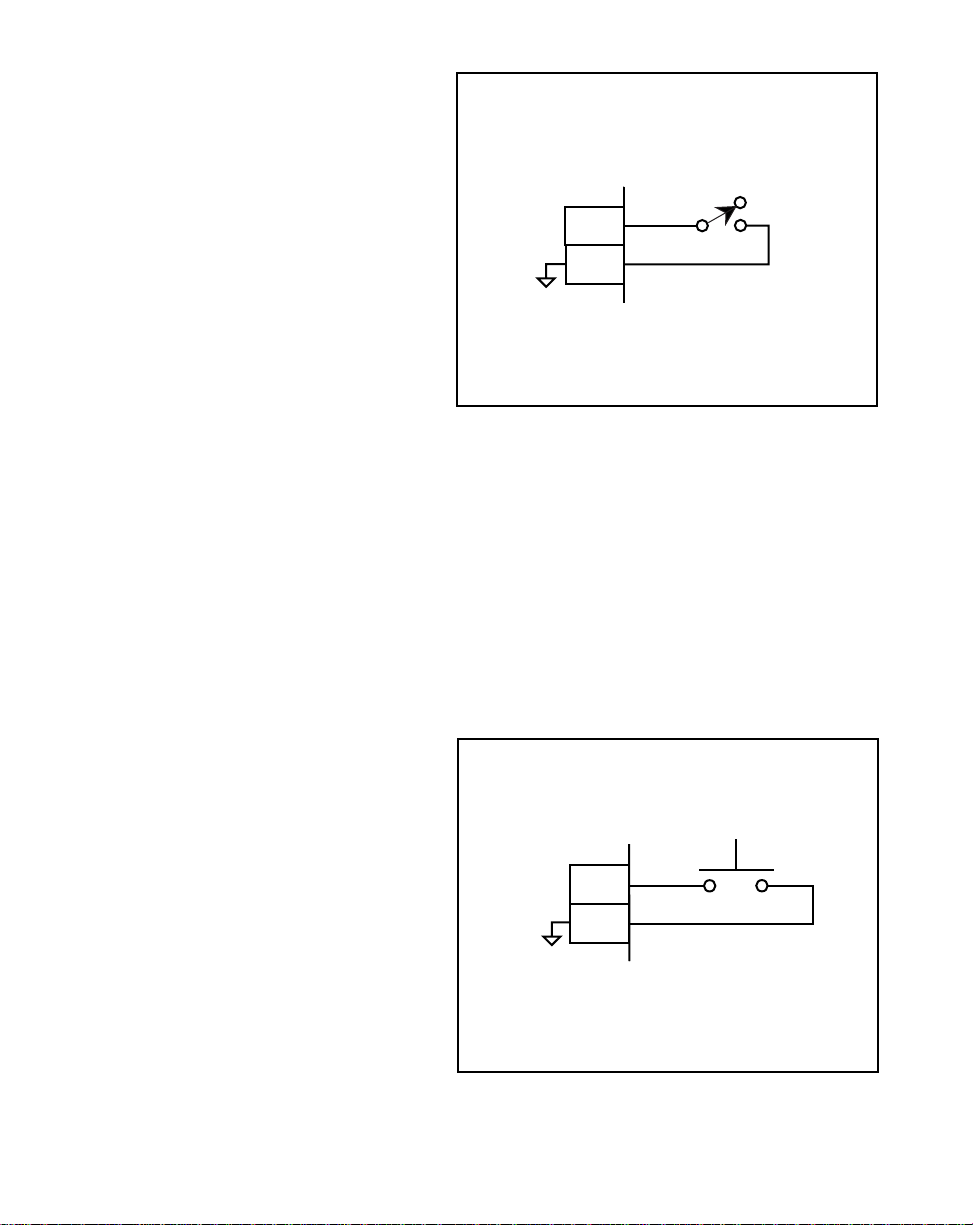
Home Set (J3 pins 14,16)
Home Set is a momentary input that
is edge triggered. When Home Set is
closed, it sets the current position as
the new “Home” position.
Home Set
14
16
J3
Figure 2-12 Home Set
Home Seek (J4 pins 1,2)
Home Seek is a momentary input that
is edge triggered. When Home Seek
is closed, the Follower makes a
sustained move at Jog speed, until it
reaches the “Home” sensor. As a
momentary input, Home Seek is
internally latched and does not need
to be maintained by an operator
device.
Home Seek
1
2
J4
Figure 2-13 Home Seek
2 - 13
Page 29

Home Return (J4 pins 3,4)
Home Return is a momentary input
that is edge triggered. When Home
Return is closed, the follower returns
to the established “Home” position.
As a momentary input, Home Return
is internally latched and does not
need to be maintained by an operator
device.
Home Return
3
4
J4
Figure 2-14 Home Return
Batch Reset (J4 pins 4,5)
In a closed position, the Batch Reset
input resets the batch count to zero.
2 - 14
Batch Reset
4
5
J4
Figure 2-15 Batch Reset
Page 30

Run (J4 pins 6,7)
When the Run input is momentarily
closed, the M–Traverse enters Run.
As a momentary input, Run is
internally latched and does not need
to be maintained by an operator
device.
NOTE: Close the F–Stop input prior
to entering Run.
RUN
6
7
J4
Figure 2-16 Run
Wait (J4 pins 7,8)
When the M–Traverse is in Run, it
checks the Wait input before it
proceeds with the next profile move
in either the forward or reverse
direction. If the Wait input is closed,
it will pause at the end of the profile
until the wait input opens.
Wait
8
7
J4
Figure 2-17 Wait
2 - 15
Page 31

F-Stop (J4 pins 9,10)
F-Stop is a momentary input. When
it is opened, the Follower stops
immediately (zero RPM) and ignores
the specified deceleration rate. As a
momentary input, F-STOP is
internally latched and does not need
to be maintained by an operator
device.
F-STOP
9
10
J4
Figure 2-18 F-Stop
Keypad Lockout (J4 pins 10,11)
When the Keypad Lockout is closed,
it selectively disables the front
keypad so that setpoint and other
control parameters can not be
changed. All of the monitoring
functions remain enabled.
2 - 16
10
11
J4
Keypad
Lockout
Figure 2-19 Keypad Lockout
Page 32

Forward Limit (J4 pins 12,13)
When Forward Limit is closed (edgetriggered), it prevents the follower
from moving forward. When the
M–Traverse detects a Forward Limit,
it will go to F–Stop from Forward Jog,
Home Seek or Run, if CP-37 is set to
“1”. If CP-37 is set to “2”, then the
M-Traverse will begin a reverse
profile when it detects a Forward
Limit. To deactivate Forward limit,
use any reverse command (e.g.,
Reverse Jog).
12
13
J4
Forward
Limit
Figure 2-20 Forward Limit
Reverse Limit (J4 pins 13,14)
When Reverse Limit is closed (edgetriggered), it prevents the follower
from moving in reverse. When the
M–Traverse detects a Reverse Limit,
it will go to F–Stop from either Run,
Reverse Jog or Home Seek (any
reverse move). To deactivate
Reverse limit, use any forward
command (e.g., Forward Jog).
13
14
J4
Reverse
Limit
Figure 2-21 Reverse Limit
2 - 17
Page 33
Jog Forward/Reverse (J4 pins
15,16)
The Jog Forward/Reverse input
controls the direction of the Speed
Command Output while it is in Jog.
Jog is in the forward direction when
the input is open. Jog is in the
reverse direction when the input is
closed.
Jog (J4 pins 16, 17)
Jog Forward / Reverse
15
16
J4
Figure 2-22 Jog Forward/Reverse
Jog is a maintained input. When the
Jog input is closed, the M–Traverse
sends a Speed Command Out signal
to the drive at the selected jog speed.
As a maintained input, Jog is only
active when the operator device is
closed.
NOTE: Close the F–Stop input and
open the Run input, prior to
entering Jog.
2 - 18
Jog
17
16
J4
Figure 2-23 Jog
Page 34
OUTPUTS
NOTE: The installation of this motor control must conform to area and local electrical
codes. See
National Fire Protection Association, or
Use local codes as applicable.
Speed Command Out
(J1 pins 8, 9,10,11)
The National Electrical Code
The Canadian Electrical Code
(NEC,) Article 430 published by the
(CEC).
Speed Command Out is an isolated
analog output signal that is sent to
the motor drive to control the speed
of the motor. Wire the Speed
Command Out (J1 pin 9) into the
± V (15V Max)
SIGNAL INPUT
DRIVE COMMON
*
Voltage Reference
Speed Command Out
Isolated Common
Shield
8
9
10
11
Speed Signal Input of the drive. If
the motor drive has a potentiometer
MOTOR DRIVE
J1
speed control, remove the
potentiometer connections, then wire
the Speed Command Output to the
potentiometer wiper input and wire
the Voltage Reference and Isolated
Figure 2-24 Speed Command Out
Common to the other two
potentiometer input connections. The
M–Traverse's isolated common
should always be connected to the
drive common.
Drive Enable (J1 pin 13)
The Drive Enable output is activated (driven low) when the M–Traverse is signaling a
speed command to the motor drive. The Drive Enable output is driven high (relay
deactivated) after Power Up and during F–Stop. Refer to Figure 2-25.
NOTE: This is an open-collector relay driver. For specification details, see
ences: Appendix A, M–Traverse Specifications
. Use an external DC power
supply to power the relays. Free-wheeling diodes are incorporated internally
in the M–Traverse and do not need to be added externally.
Refer-
2 - 19
Page 35

Batch Done (J1 pin 14)
The Batch Done output is relay activated (driven low ) when the Batch count is
completed. Refer to Figure 2-25.
NOTE: This is an open-collector relay driver. For specification details, see
ences: Appendix A
supply to power the relays. Free-wheeling diodes are incorporated internally
in the M–Traverse and do not need to be added externally.
,
M–Traverse Specifications
. Use an external DC power
Refer-
Alarm (J1 pin 15)
The Alarm output is relay activated (driven low) if the system's speed is above the
speed alarm setting that has been entered in the High Speed Alarm (CP-23) parameter.
Refer to Figure 2-25.
NOTE: This is an open-collector relay driver. For specification details, see
ences: Appendix A
supply to power the relays. Free-wheeling diodes are incorporated internally
in the M–Traverse and do not need to be added externally.
,
M–Traverse Specifications
. Use an external DC power
Refer-
Profile Direction (J1 pin 16)
The Profile Direction output indicates the commanded direction of the profile.
This output is relay deactivated (driven high) when the profile is commanded to move
forward. This output is relay activated (driven low) when the profile is commanded to
move in reverse. Refer to Figure 2-25.
NOTE: This is an open-collector relay driver. For specification details, see
ences: Appendix A, M–Traverse Specifications
supply to power the relays. Free-wheeling diodes are incorporated internally
in the M–Traverse and do not need to be added externally.
2 - 20
. Use an external DC power
Refer-
Page 36

At-Home (J1 pin 17)
In order for this output to function, “Home” must have already been determined (using
Home Set or Home Seek). Once ”Home” has been determined, this output is relay
activated (driven low) when the traverse Follower Position is within the At-Home Band
specified in CP-30. Refer to Figure 2-25.
NOTE: This is an open-collector relay driver. For specification details, see
ences: Appendix A
supply to power the relays. Free-wheeling diodes are incorporated internally
in the M–Traverse and do not need to be added externally.
,
M–Traverse Specifications
. Use an external DC power
Refer-
Output A (J1 pin 18)
Output A can be set to activate at different segments of the forward and reverse
profiles. The parameter values set in CP-90, CP-91 and CP-92 determine the profile
segment and direction of activation, as well as the polarity (high or low). Refer to
Figure 2-25.
NOTE: This is an open-collector relay driver. For specification details, see
ences: Appendix A
supply to power the relays. Free-wheeling diodes are incorporated internally
in the M–Traverse and do not need to be added externally.
,
M–Traverse Specifications
. Use an external DC power
Refer-
Output B (J1 pin 19)
Output B can be set to activate at different segments of the forward and reverse
profiles. The parameter values set in CP-93, CP-94 and CP-95 determine the profile
segment and direction of activation, as well as the polarity (high or low). Refer to
Figure 2-25.
NOTE: This is an open-collector relay driver. For specification details, see
ences: Appendix A, M–Traverse Specifications
supply to power the relays. Free-wheeling diodes are incorporated internally
in the M–Traverse and do not need to be added externally.
. Use an external DC power
Refer-
2 - 21
Page 37

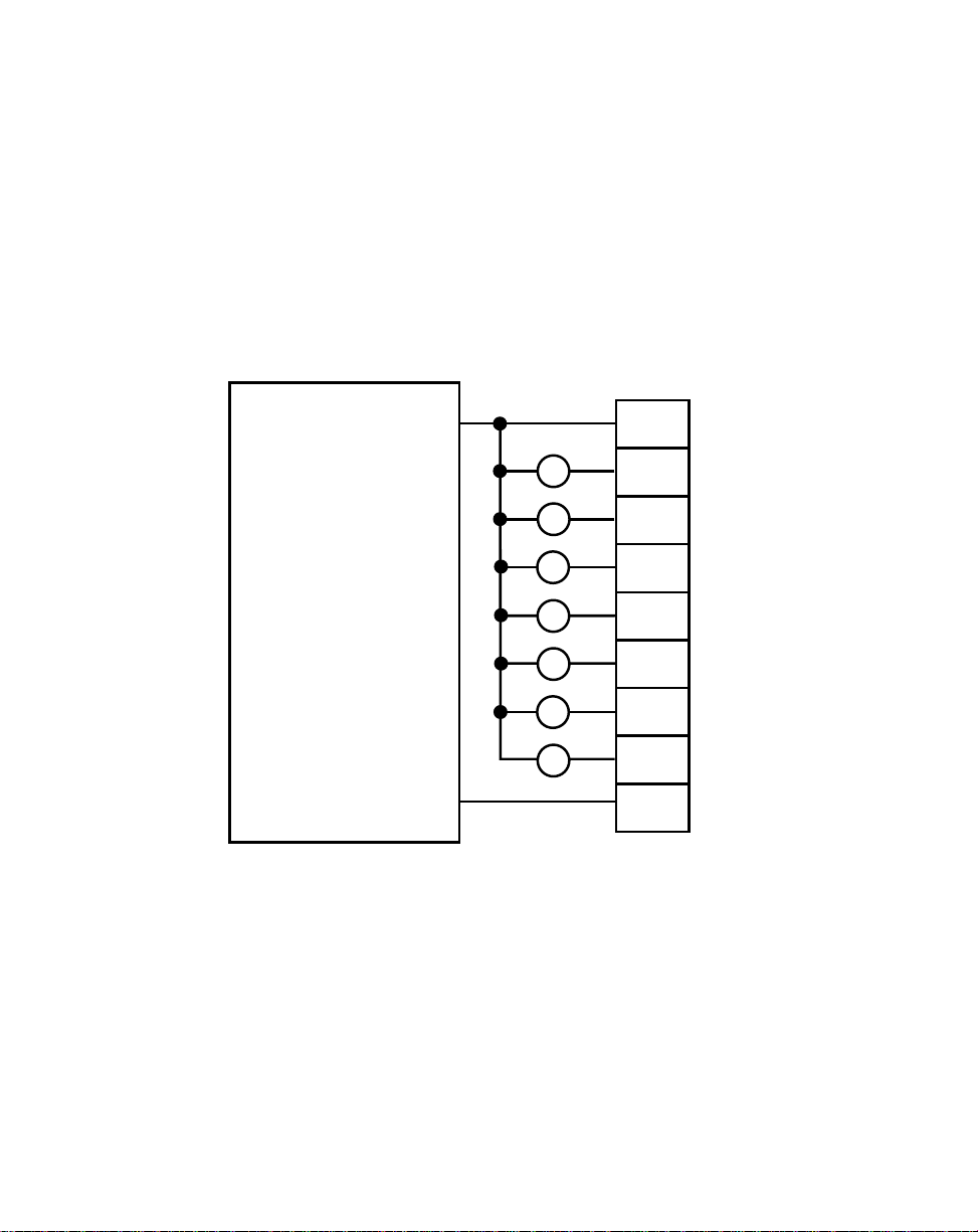
Auxiliary DC Power (J3 pins 1, 2)
The 5 volt output (J3 pin 1) is a DC regulated output that can be used to power
encoders or other auxiliary equipment that is used in conjunction with the M–Traverse.
The 12 volt output (J3 pin 2) is a DC regulated output that can be used to power the
proximity sensors or other auxiliary equipment that is used in conjunction with the M–
Traverse. Refer to Figure 2-25.
WARNING
Do not exceed
the maximum current output of
250 mA for +5 VDC and
200 mA for +12 VDC.
2 - 22
Exceeding the maximum
current output
can damage the M–Traverse.
Page 38
+
12
Diode Protect
EXTERNAL
DC
POWER
SUPPLY
(50V Max)
R
R
R
R
R
R
R
–
13
14
15
16
17
18
19
20
Drive Enable
Batch Done
Alarm
Profile Dir
At-Home
Output A
Output B
Common
J1
Figure 2-25 Discrete Outputs
2 - 23
Page 39

SERIAL COMMUNICATIONS
NOTE: The installation of this motor control must conform to area and local electrical
codes. See
National Fire Protection Association, or
Use local codes as applicable.
The Serial Communications interface on the M–Traverse complies with EIA Standard
RS–422 for balanced line transmissions. This interface allows the host computer to
perform remote computer parameter entry, status or performance monitoring, and
remote control of the M–Traverse. See
information on using Serial Communications.
Figures 2-26 and 2-27 illustrate a multidrop installation of the Serial Communications
link and Serial Communications connections.
The National Electrical Code
The Canadian Electrical Code
Operations: Serial Communications
(NEC,) Article 430 published by the
(CEC).
for
2 - 24
M-TRAVERSE
M-TRAVERSE
RS-232 to RS-422
Converter
M-TRAVERSE
Figure 2-26 M-Traverse Multidrop Installation
M-TRAVERSE
M-TRAVERSE
M-TRAVERSE
Page 40
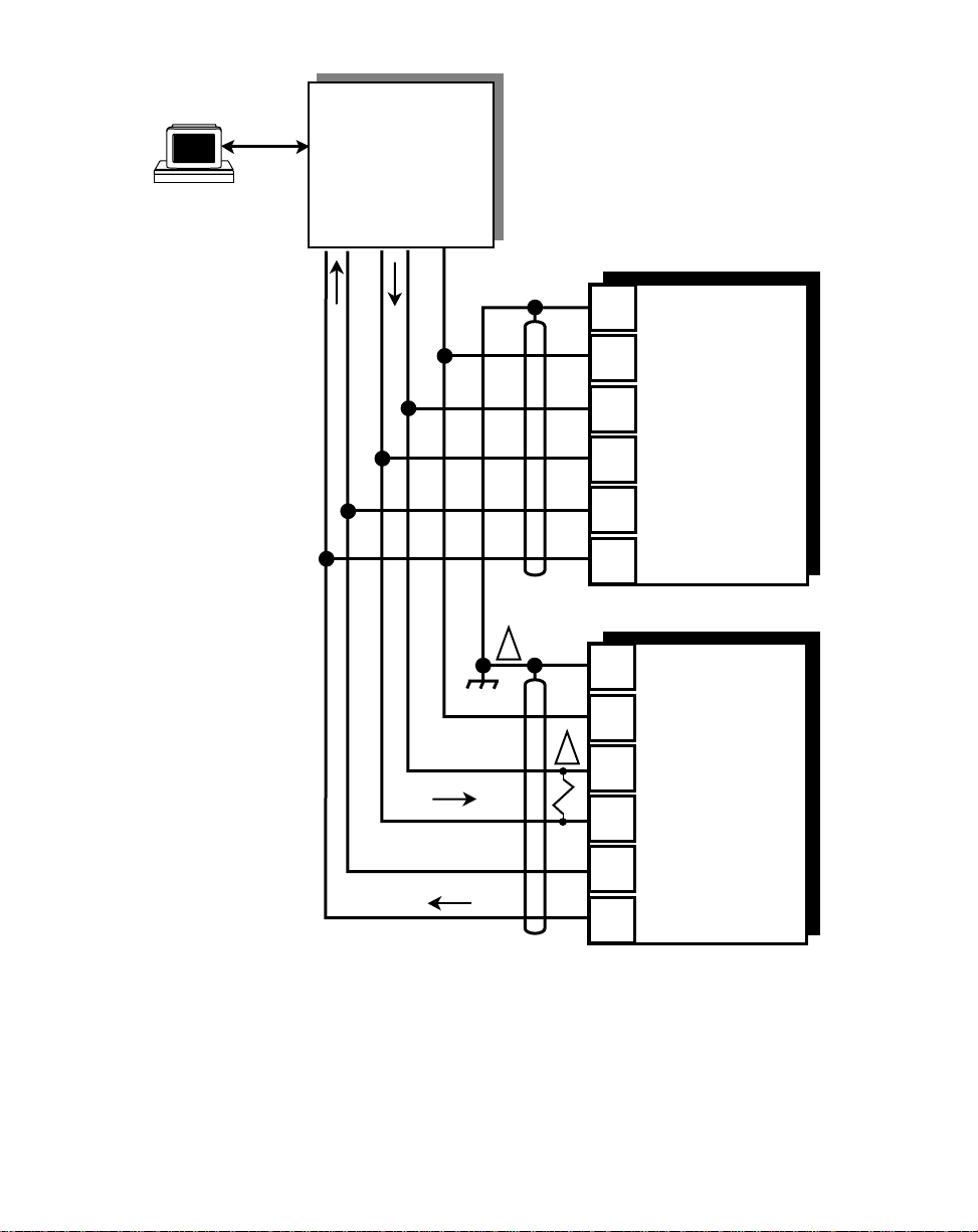
RS232 to RS422
Converter
RXD TXD COM
+ — + —
J1
7
6
5
4
3
2
M-Traverse #1
SHIELD
COMMON
- RXD
+ RXD
- TXD
+ TXD
J1
1
1. Terminate shield only at one end of the cable.
2. If you need to terminate the communication line, then
terminate it at the unit which is the furthest away from
the converter. A 100 ohm, 1/2 Watt resistor will usually
terminate successfully. Refer to EIA Standard
RS–422, for more information.
Figure 2-27 M–Traverse Serial Communications Connections
7
6
2
5
4
3
2
M-Traverse #2
SHIELD
COMMON
- RXD
+ RXD
- TXD
+ TXD
2 - 25
Page 41

2 - 26
Page 42

CALIBRATION
Calibration matches the analog output of the M–Traverse with the analog input of the
motor drive. Calibration is accomplished in two steps. The first step is to set up the
motor drive. The second step is to calibrate the M–Traverse to the motor drive so that
the speed is adjusted to the maximum operating speed. The M–Traverse must be
properly installed prior to calibration. Refer to
Installation/Setup; Wiring
.
DANGER
Hazardous voltages.
Can cause severe
injury, death or
damage
to the equipment.
Installation/Setup; Mounting
and
Make adjustments with caution.
2 - 27
Page 43

Turn the screws fully clockwise for the maximum setting.
Turn the screws fully counterclockwise for the minimum setting.
Zero Pot
Scale Pot
R1
R2
2 - 28
Power Board
Figure 2-28 Location of M–Traverse Scale and Zero Pot
Page 44

MOTOR DRIVE SET UP
1) Put the M–Traverse in “F–Stop” by opening the F–Stop input (J4 pins 9
and 10). Refer to
2) Set the drive's Acceleration and Deceleration potentiometers to their
fastest rates (minimum ramp time). The goal is to make the drive as
responsive as possible, which allows the M–Traverse to control the
speed changes.
3) If the drive has a Zero Speed Potentiometer, adjust it to eliminate any
motor creep. If the drive does not have a zero speed pot, then adjust
the zero speed pot on the M–Traverse to eliminate any motor creep.
Figure 2-28 shows the location of the M–Traverse zero speed pot.
4) If the drive has an IR Compensation Potentiometer, set it at minimum.
5) Each motor drive has settings that are unique to its particular model.
Adjust any remaining drive settings according to the manufacture's
recommendations.
Installation/Setup: Wiring, F–Stop.
ENCODER POLARITY CHECK
1) Observe MV-41 while you rotate the lead encoder in the direction that is
“forward” during normal operation. Switch the lead encoder lines on J3
pins 3 and 5 if MV-41 is negative.
2) Observe MV-42 while you rotate the Follower encoder in the direction
that is “forward” during normal operation. Switch the follower encoder
lines on J3 pins 7 and 9 if MV-42 is negative.
2 - 29
Page 45

M–TRAVERSE CALIBRATION
1) Make sure that the M–Traverse is still in “F–Stop”. If it is not, put the
M–Traverse in “F–Stop” by opening the F–Stop Logic input (J4 pins 9
and 10). Refer to
2) Enter the resolution (PPRs) of the feedback sensor in the PPR Follower
(CP-18) parameter by entering the following on the keypad:
Press “Code Select”
Enter “18”
Press “Enter”
Enter the Pulses Per Revolution (PPR) of the feedback sensor
Press “Enter”
The Tach is now scaled for feedback RPMs.
3) If the M–Traverse is using the drive voltage for reference (J1 pin 8),
then set the drive's max speed potentiometer to its minimum setting. If
the M–Traverse is using its internal voltage for reference (no
connection to J1 pin 8) then set the drive's max speed potentiometer to
its maximum setting and set the M–Traverse's scale pot to its minimum
setting (fully counterclockwise). Figure 2-28 shows the location of the
M–Traverse scale pot.
Installation/Setup: Wiring, F–Stop
.
2 - 30
4) The M-Traverse is defaulted for use with bi-directional drives that use
bipolar (positive and negative) voltage commands to indicate the
direction. If you are using a single quadrant (direction) drive, then
change CP-29 to unipolar operation, as follows:
Press “Code Select”
Enter “29”
Press “Enter”
Enter “1”
Press “Enter”
5) Enable the M–Traverse's direct control mode by entering the following
on the keypad:
Press “Code Select”
Enter “14”
Press “Enter”
Enter “2”
Press “Enter”
Page 46

6) Put the M–Traverse into RUN by shorting the F–STOP input (J4 pins 9
and 10) and the RUN input (J4 pins 6 and 7). Although the motor is
now in RUN, it will have zero speed until you adjust the Direct Analog
Command (CP-62).
7) Gradually set the M–Traverse's Direct Analog Command to 90% (3686)
by entering the following on the keypad:
Press “Setpoint”
Enter “400”
Press “Enter”
Enter “800”
Press “Enter”
Continue to gradually increase these increments by 400 until you reach
“3686”. Since there are no acceleration/deceleration ramps in Direct
mode, a sudden increase to “3686” could cause damage in some
systems. If the Follower is not moving in a forward direction, then
rewire the drive/motor leads for forward operation.
Note: A value of –3686 will change the direction of the motor.
8) Turn either the motor drive's max speed or the M–Traverse's scale
potentiometer clockwise until the drive motor's RPMs are at the
maximum operating speed at which you want the system to operate.
Check the speed (RPMs) by pressing the Tach” key. “Tach” should
display the RPM speed that you enter in CP-19.
9) Put the Direct Analog Command back to 0% by entering the following
on the keypad:
Press “Setpoint”
Enter “0”
Press “Enter”
10) Disable the M–Traverse's direct mode by entering the following on the
keypad:
Press “Code Select”
Enter “14”
Press “Enter”
Enter “1”
Press “Enter”
11) Put the M–Traverse in “F–Stop” by opening the F–Stop input (J4 pins 9
and 10). Refer to
Installation/Setup: Wiring, F–Stop
.
2 - 31
Page 47

—NOTES—
2 - 32
Page 48

Operation
Keypad Operation
Control Parameters (CP)
Follower Mode
Direct Mode
Jog
Tuning
Output Control
M-Traverse Operation
Follower Mode
Home Set
Home Seek
Home Return
Direct Mode
Jog
Monitor Variables (MV)
Input Monitoring
Output Monitoring
Performance Monitoring
Status Monitoring
Serial Communications
Using Serial Communications
Communications Software Design
3 - 1
Page 49

3 - 2
Page 50

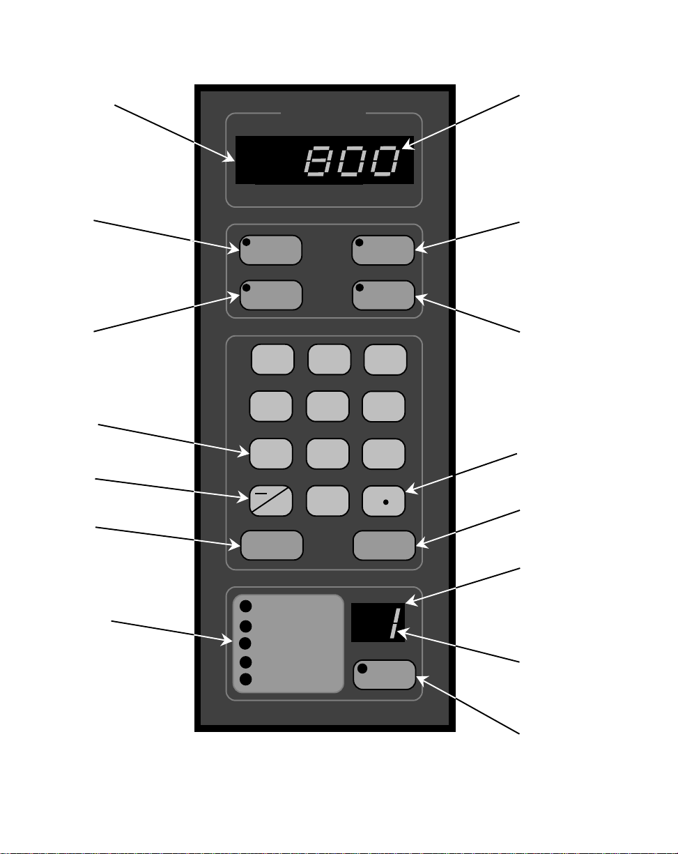
KEYPAD OPERATION
The front panel of the M–Traverse is an easy to use keypad that gives you direct
access to the Parameters (Control Parameters and Monitor Variables) by entering the
Parameter Code. You can also use the keypad to change the value of a Control
Parameter. The keypad has keys for Code Select, Enter and Clear. It also has
numeric keys and four dedicated keys: Setpoint, Tach, Status and Batch Count. The
LED display is the above the keys. Refer to figure 3-1 for the location of the keys and
LED display on the keypad. Table 3-1 demonstrates basic keypad entry.
The keypad functions as follows:
Code Select Use the “Code Select” key prior to entering a Parameter Code
for either a Control Parameter (CP) or Monitor Variable (MV).
Numeric Use the numeric keys to enter a Parameter Code for either a
Control Parameter (CP) or a Monitor Variable (MV) or to enter
a value for a Control Parameter. Use the “Clear” key to delete
your entry. Use the “Enter” key after each entry, to enter it in
the M-Traverse.
—/Alt Use the “—/Alt” key to enter a negative value. In MVs 43, 44,
80, 81 and 84, the “—/Alt” key toggles between four lower and
four higher digits because some numbers exceed the six digit
display panel limit.
. Use the decimal key for values with a decimal point.
Clear The “Clear” key will delete the entry, if you have not used the
“Enter” key.
Tach The “Tach” key is a dedicated or shortcut key. You can access
the tach Parameters directly, rather than manually entering the
Parameter Code (MV-40).
Setpoint The “Setpoint” Key is a dedicated or shortcut key. You can
directly access the active setpoint in the Follower mode (either
CP-01, CP-03, CP-05 or CP-07) or the active setpoint in the
Direct mode (CP-62).
3 - 3
Page 51

Batch Count Key The “Batch Count” Key is a dedicated or shortcut key. You can
directly access the Batch Count parameter (MV-89).
Status Key The “Status” Key is a dedicated or shortcut key. You can
directly access the Alarm Status parameter (MV-51).
Lower LED Display The two-digit Parameter Code is displayed on the Lower LED
Display.
Upper LED Display The Parameter Code's value is displayed on the Upper LED
display. This value can be up to six digits.
Discrete LED Display There are five discrete LED display lights. When a specific
light is “on”, it indicates the following condition:
Run..................The M-Traverse is in Follower mode and is executing
a profile.
Wait .................The Wait input (J4 pin 8 ) is active.
Drive Enable....The Drive Enable output (J1 pin 13) is active.
At-Home ..........The Follower position is within the At-Home band of
the Home position.
Alarm ............... There is an active alarm condition.
To Enter a Parameter Code:
To Enter a Parameter Value:
(For Control Parameters only - Monitor
Variables can not be changed
manually)
To Use the Tach Key:
To Use the Status Key:
To Use the Setpoint Key:
To Use the Batch Count Key:
3 - 4
Table 3-1 Basic Keypad Entry
Press “Code Select”.
Enter a Parameter Code (For a Control Parameter or Monitor Variable).
Press “Enter” (within 15 seconds).
The Parameter Code and its current value are displayed on the LED displays.
Follow the steps to enter a Parameter Code.
Enter a new value (Use the numeric keys) .
Press “Enter” (within 15 seconds).
Press “Tach”.
The scaled Tach - Velocity is displayed (MV -40).
Press “Status”.
The code for the alarm status is displayed (MV-51).
Press “Setpoint”.
The value of the active setpoint is displayed, in engineering units. (CP-01,
CP-03, CP-05, CP-07 or CP-62).
Press “Batch Count” .
The number of complete batch counts is displayed (MV-89).
Page 52
Upper
LED
Display
Setpoint
Key
Set
Point
ONTREX
C
Parameter Value
(up to 6 digits)
Tach
Key
Tach
Batch
Count
Key
Numeric
Keys
—/Alt
Key
Clear
Key
Discrete
LED Indicator
Display
Batch
Count
7
8
45
1
Alt
23
0
Clear
Run
Wait
Drive Enbl
At-Home
Alarm
Status
9
6
Enter
Code
Select
Status
Key
Decimal
Key
Enter
Key
Lower
LED
Display
Parameter
Code
(2 digits)
Figure 3-1 The M–Traverse Front Panel
Code
Select
Key
3 - 5
Page 53

3 - 6
Page 54
CONTROL PARAMETERS
Parameters are divided into two classifications; Control Parameters (CP) and Monitor
Variable (MV). The numbered code that represents the parameter is the Parameter
Code. The operational data is the parameter's value.
Control Parameter 14 = 1
Parameters =
Monitor Variable 40 = 200
Parameter Code Parameter Value
This section is about Control Parameters. Monitor Variables are explained in
Operation: Monitor Parameters.
The M–Traverse comes factory pre-loaded with a complete set of default Control
Parameters values. The majority of these default settings are suitable for most
applications and do not require modification.
Control Parameters allow you to enter data that is unique to your system (e.g., encoder
resolution, Lead to Follower ratios) and modify the M–Traverse for your specific needs
(e.g., maximum RPM, setpoints, acceleration/deceleration ramp rates) by entering a
parameter value. Control Parameters can be "locked out" so that they become
inaccessible from the Keypad. For details, refer to
References: Appendix C, CP-79.
The M–Traverse is designed to execute either the Direct mode of operation or the
Follower mode of operation. The values that you enter in the relevant Control
Parameters determine which of the modes of operation your M–Traverse is set up for.
The mode of operation that you use is determined by your systems operational
requirements.
The following sections demonstrate how to enter Control Parameters for the Direct
mode or the Follower mode of operation. In addition, Control Parameters for Jog,
Tuning and Output Control are addressed.
3 - 7
Page 55

FOLLOWER MODE
The M-Traverse is a multi-motor operation that is specifically designed for the precise
control of reciprocating lead/follower motion control applications. Its primary mode of
operation is the Follower mode. This section discusses the set up procedures for the
Follower mode of operation. Refer to
Applications
Operation
Caution: To avoid damage to your system, the M-Traverse must be calibrated and the
In order to set up the M-Traverse for the Follower mode of operation, Control
Parameters must be entered for the following procedures:
for an example of the Follower Mode. Refer to
for instructions on the operation of the Follower mode.
motor drive set up before you enter the Follower mode. Refer to
Setup: Calibration
.
Introduction: Examples of M-Traverse
Operation: M–Traverse
Installation/
Control Mode Parameter
Follower Scaling Parameters
Preset Parameters
Follower Profile Parameters
Other Follower Parameters
3 - 8
Page 56
Control Mode Parameter
The Control Mode (CP-14) parameter allows you to choose between either the
Standard (1) or Lay Adjusted (3) option in the Follower mode of operation. Both options
will operate your system. The calculation of the Follower profile length is the only
difference between the Standard and the Lay Adjusted option. In the lay adjusted
option, one lay pitch is subtracted from the profile length to adjust for the initial lay on
the reel.
NOTE: You can also use Control Mode (CP-14) to choose the Direct mode of opera-
tion, which is used for calibration and trouble shooting. Refer to
Direct Mode
The factory default for the Control Mode Control Parameter is found in Table 3-2. To
modify the default parameter refer to Table 3-3. If you are uncertain how to enter a
Control Parameter, review the
for information on the Direct mode.
Operations: Keypad
Table 3-2 Default Control Mode Control Parameter
section.
CP Parameter Name Parameter Value
CP-14 Control Mode 1 (Follower /Standard)
Operation:
Table 3-3 Entering Control Mode Control Parameters
CP Parameter Name Parameter Value
CP-14 Control Mode Enter “1” to enable the Follower Mode / Standard
Enter “3” to enable the Follower Mode / Lay Adjusted
3 - 9
Page 57

Follower Scaling Parameters
The M-Traverse allows you to use Engineering Units (e.g., feet, inches) to control and
monitor your system. Follower Scaling is a convenient method for converting encoder
lines to Engineering Units. Scaling Control Parameters give the M-Traverse the
following information:
Engineering Units (CP-15)
In a level wind application, CP-15 is your Engineering Unit (E.U.)
measurement of a laypitch. In a web scanning application, CP-15 is
your E.U. measurement for a traverse length. If your application uses
the M-Traverse's setpoint flexibility to change over the operation, and
you have more than one measurement, then pick one arbitrarily.
However, be sure to reference that same measurement consistently
throughout the scaling set up. In setting up the scaling, you are simply
allowing the M-Traverse to establish a conversion of encoder lines to
the E.U. that you prefer to use. Place the decimal in the location of
your desired resolution (to the tens, hundreds or thousands place). All
of the other Control Parameters or Monitor Parameters that display in
E.U.s will automatically display the correct decimal position.
Lead PPR Reel (CP-16)
In a level wind application, CP-16 is the number of Lead encoder lines
that the Lead Frequency input registers as a result of one revolution of
the reel. In a web scanning application, CP-16 is the number of Lead
encoder lines that the Lead Frequency input registers when the
Follower travels one traverse length. When you calculate this variable,
be sure to consider all gear reductions, belt reductions and other types
of reducers. Use the following procedure to check CP-16:
• Place the M-Traverse in F-Stop.
• Activate the Home Set input (clears the Lead position to zero).
• Place the M-Traverse in F-Stop.
• Display MV-43 (Lead Position).
• Move the Lead either one revolution of the reel (level wind) or one
traverse length (web scan).
• MV-43 should have the same value as CP-16.
Follower Lines per Engineering Units (CP-17)
In a level wind application, CP-17 is the number of Follower encoder
lines that the Feedback Frequency input registers as a result of the
Follower laypitch that was entered in CP-15. In a web scanning
application,
3 - 10
Page 58

CP-17 is the number of Follower encoder lines that the Feedback
Frequency input registers when the Follower travels one traverse
length. When you calculate this variable, be sure to consider all gear
reductions, belt reductions and other types of reducers. Use the
following procedure to check or find CP-17 :
• Place the M-Traverse in F-Stop.
• Activate the Home Set input (clears the Follower position to zero).
• Place the M-Traverse in F-Stop.
• Display MV-44 (Follower Position).
• Jog the Follower either one laypitch (CP-15) for level wind or one
traverse length( CP-15) for web scan.
• MV-44 should have the same value as CP-17.
PPR Follower (CP-18)
The PPR Follower (CP-18) parameter is the number of pulses per
revolution of the feedback encoder (encoder resolution in lines).
Maximum RPM Follower (CP-19)
The Maximum RPM Follower (CP-19) parameter is the RPM of the
feedback encoder shaft when the Follower is operating at maximum
speed. Although this entry does not need to be exact, highly inaccurate
entries will make it difficult to tune the M-Traverse for precision Follower
profiling. When you calculate this variable, be sure to consider all gear
reductions, belt reductions and other types of reducers.
The factory defaults for the Follower Scaling Control Parameters are found in Table 3-4.
To modify the default parameters refer to Table 3-5. If you are uncertain how to enter a
Control Parameter, review the
Operations: Keypad
section.
Table 3-4 Default Follower Scaling Control Parameters
CP Parameter Name Parameter Value
CP-15 Engineering Units 0.000
CP-16 Lead PPR Reel 1000
CP-17 Follower Lines/E.U. 1000
CP-18 PPR Follower (Feedback) 60
CP-19 Max RPM Follower 2000
3 - 11
Page 59

Table 3-5 Entering Follower Scaling Control Parameters
CP Parameter Name Parameter Value
CP-15 Engineering Units In a level wind application, enter your E.U.
measurement of one laypitch.
In a web scanning operation, enter your E.U.
measurement for one traverse length.
CP-16 Lead PPR Reel In a level wind application, enter the number of Lead
encoder lines that the Lead Frequency input registers as
a result of one revolution of the reel.
In a web scanning application, enter the number of Lead
encoder lines that the Lead Frequency input registers as
a result of one traverse length.
Include calculations for all gear reductions, belt
reductions and other types of reducers.
CP-17 Follower Lines/E.U. In a level wind application, enter the number of Follower
encoder lines that the Feedback Frequency input
registers as a result of one Follower laypitch (reference
CP-15).
In a web scanning application, enter the number of
Follower encoder lines that the Feedback Frequency
input registers when the Follower travels one traverse
length. Include calculations for all gear reductions, belt
reductions and other types of reducers.
CP-18 PPR Follower (fdbk) Enter the number of pulses per revolution of the
feedback encoder (encoder resolution in lines).
CP-19 Max RPM Follower Enter the RPM of the feedback encoder shaft when the
Follower is operating at maximum speed. Include
calculations for all gear reductions, belt reductions and
other types of reducers.
3 - 12
Page 60

Preset Parameters
Setpoints (CP-01, CP-03, CP-05, CP-07)
The Setpoint parameters are set up as pairs in conjunction with the
Traverse Length parameters. There are four pairs of Setpoint and
Traverse Length parameters. The Setpoint value is entered in Engineering Units (E.U.s) and automatically displays the decimal position
that was entered in the Engineering Units (CP-15). The Setpoint
parameter determines how far the Follower travels based on the Lead.
The Follower travels the setpoint distance while the Lead travels the
distance entered into CP-17. In the level wind application, the Setpoint
parameters are the laypitch (center-to-center distance between windings on the reel). In the web scanning application, the Setpoint parameters are the traverse length. These preset parameters can be switch
selected (via the Setpoint Select switches) which gives the operator the
option of changing over the product up to four times.
The factory defaults for the Default Setpoint Control Parameters are found in Table 3-6.
To modify the default parameters refer to Table 3-7. If you are uncertain how to enter a
Control Parameter, review the
Operations: Keypad
section.
Table 3-6 Default Setpoint Control Parameters
CP Parameter Name Parameter Value
CP-01 Setpoint 1 0.000
CP-03 Setpoint 2 0.000
CP-05 Setpoint 3 0.000
CP-07 Setpoint 4 0.000
3 - 13
Page 61

Table 3-7 Entering Setpoint Control Parameters
CP Parameter Name Parameter Value
CP-01 Setpoint 1 In a level wind application, enter your E.U.
measurement of one laypitch.
In a web scanning operation enter your E.U.
measurement for one traverse length.
CP-03 Setpoint 2 In a level wind application, enter your E.U.
measurement of one laypitch.
In a web scanning operation enter your E.U.
measurement for one traverse length.
CP-05 Setpoint 3 In a level wind application, enter your E.U.
measurement of one laypitch.
In a web scanning operation enter your E.U.
measurement for one traverse length.
CP-07 Setpoint 4 In a level wind application, enter your E.U.
measurement of one laypitch.
In a web scanning operation enter your E.U.
measurement for one traverse length.
Traverse Length (CP-02, CP-04, CP-06, CP-08)
The Traverse Length parameters are set up as pairs in conjunction with
the Setpoint parameters. There are four pairs of Setpoint and Traverse
Length parameters. The Traverse Length value is entered in Engineering Units (E.U.s) and the decimal position that was entered in the
Engineering Units (CP-15) parameter is automatically displayed. The
traverse length is the distance that the Follower mechanism will travel.
In level wind applications, the traverse length is generally the length of
the reel. In web scanning applications, the traverse length is generally
the width of the web. The traverse length measurement, corresponds
to the setpoint measurement. For example, in a level wind application,
you may have a reel that measures one foot, that is wrapped with two
inch hose. You would enter "2" (inches) in Setpoint 1 (CP-01) and "12"
(inches) in Traverse Length 1 (CP-02).
The factory defaults for the Traverse Length Control Parameters are found in Table 3-8.
To modify the default parameters refer to Table 3-9. If you are uncertain how to enter a
Control Parameter, review the
3 - 14
Operations: Keypad
section.
Page 62

Table 3-8 Default Traverse Length Control Parameters
CP Parameter Name Parameter Value
CP-02 Traverse Length 1 0.000
CP-04 Traverse Length 2 0.000
CP-06 Traverse Length 3 0.000
CP-08 Traverse Length 4 0.000
Table 3-9 Entering Traverse length Control Parameters
CP Parameter Name Parameter Value
CP-02 Traverse Length 1 In a level wind application, enter your reel length in
E.U.s (reference Setpoint 1).
In a web scanning operation, enter the width of your
web, in E.U.s (reference Setpoint 1).
CP-04 Traverse Length 2 In a level wind application, enter your reel length in
E.U.s (reference Setpoint 2).
In a web scanning operation, enter the width of your
web, in E.U.s (reference Setpoint 2).
CP-06 Traverse Length 3 In a level wind application, enter your reel length in
E.U.s (reference Setpoint 3).
In a web scanning operation, enter the width of your
web, in E.U.s (reference Setpoint 3).
CP-08 Traverse Length 4 In a level wind application, enter your reel length in
E.U.s (reference Setpoint 4).
In a web scanning operation, enter the width of your
web, in E.U.s (reference Setpoint 4).
3 - 15
Page 63

The following chart demonstrates how Setpoint and Traverse Length
pairs are selected by the various positions of the Setpoint Select A and
Setpoint Select B discrete inputs.
Setpoint Select B
Setpoint Select B
Open
Open
Setpoint Select B
Closed
(Closed = shorted to common)
Setpoint Select A
Open
Setpoint 1(CP-01)
Traverse Length 1(CP-02)
Setpoint 3 (CP-05)
Traverse Length 3 (CP-06)
Setpoint Select A
Closed
Setpoint 2 (CP-03)
Traverse Length 2 (CP-04)
Setpoint 4 (CP-07)
Traverse Length 4 (CP-08)
3 - 16
Page 64

Follower Profile Parameters
In addition to being part of a setpoint pair, the traverse length acts in conjunction with
the Accel/Decel Length (CP-09) parameter and the Dwell (CP-10) parameter to define
the Follower Profile. The Follower Profile creates a smooth transition to dwell before
reversing directions. This takes place at the reel's end in level wind applications or at
the edge of the web in web scanning applications.
Accel/Decel Length (CP-09)
The Accel/Decel Length (CP-09) parameter allows the Follower mechanism to ramp to either the constant pitch plateau or end dwell, either
gradually or rapidly. This parameter is the number of encoder lines for
the desired Accel/Decel Length. The lower the number, the more
rapidly the Follower mechanism ramps to the constant pitch plateau or
end dwell. The higher the number, the more gradually the Follower
mechanism ramps to the control pitch plateau or end dwell. As a
guideline, keep in mind that you do not want the accel/decel rate to
exceed the load that the motor drive or mechanics can accommodate.
The Accel/Decel Length parameter does not need to be an exact
number, the system will perform adequately with a close estimate.
The factory default for the Accel/Decel Length Control Parameter is found in Table 3-10.
To modify the default parameter refer to Table 3-11. If you are uncertain how to enter a
Control Parameter, review the
Operations: Keypad
section.
Table 3-10 Default Accel/Decel Length Control Parameter
CP Parameter Name Parameter Value
CP-09 Accel/Decel Length 0
Table 3-11 Entering Accel/Decel Length Control Parameter
CP Parameter Name Parameter Value
CP-09 Accel/Decel Length Enter the number of encoder lines for the desired
Accel/Decel Length.
3 - 17
Page 65
Dwell (CP-10)
The Dwell (CP-10) parameter allows the Follower mechanism to pause
at the end of the Follower profile before ramping back in the opposite
direction. In level wind applications, this parameter is a portion of the
encoder lines in one rotation of the reel (Lead). In web scanning
applications, this parameter is a portion of the encoder lines in one
traverse length. The Dwell parameter does not need to be an exact
number, the system will perform adequately with a close estimate .
The factory default for the Dwell Control Parameter is found in Table 3-12. To modify
the default parameter refer to Table 3-13. If you are uncertain how to enter a Control
Parameter, review the
Operations: Keypad
section.
Table 3-12 Default Dwell Control Parameter
CP Parameter Name Parameter Value
CP-10 Dwell 0
3 - 18
Table 3-13 Entering Dwell Control Parameter
CP Parameter Name Parameter Value
CP-10 Dwell In a level wind applications, enter a portion of the
encoder lines in one rotation of the reel
In a web scanning applications, enter a portion of the
encoder lines in one traverse length.
Page 66
Other Follower Parameters
The orientation (edge or center) of “Home,” changes in the “Home” position and
changes made on the fly, are determined by the following parameters:
Edge/Center Based Profile (CP-24)
The traverse length is measured from “Home”. The Edge/Center Based
Profile (CP-24) parameter allows you to set “Home” relative to either the
edge or the center of your reel or web. The Follower mechanism
moves a traverse length from that position and then returns.
To set “Home” as an edge based profile, enter “1” in CP-24. All
traverse length changes occur from the edge, in the forward direction
and the “Home” position does not change. The diagram below illustrates this profile. Traverse length changes can be made on the fly and
the timing on these changes is a crucial factor. For the timing on edge
based traverse length changes, refer to the Change Activation (CP-25)
parameter.
Edge Based
“Home”
12" Traverse Length
10" Traverse Length
5" Traverse Length
To set “Home” as a center based profile, enter “2” in CP-24. All
traverse length changes occur from the center and the “Home” position
changes to compensate for traverse length changes. The diagram
below illustrates this profile. Traverse length changes will occur automatically when the Follower mechanism is in the center of the web.
Center Based
C
L
“Home”
“Home”
“Home”
12" Traverse Length
10" Traverse Length
5" Traverse Length
3 - 19
Page 67
Change Activation (CP-25)
The Change Activation (CP-25) parameter works in conjunction with the
Edge/Center Based Profile (CP-24) parameter. When CP-24 is set to
“1” (edge based), then CP-25 determines when changes will occur. If
CP-24 is set to “2” (center based), then CP-25 has no effect.
Change Activation (CP-25) can be set to “1”, “2” or “3”. Settings “2” and
“3” have a number of variables:
If CP-25 is set to “1” then all of the changes will occur when the Follower is at “Home”.
If CP-25 is set to “2” and either the Accel/Decel Length or Dwell parameters are changed, the changes will only occur at “Home”.
If CP-25 is set to “2” and the setpoint speed is changed (either faster or
slower), the change will occur immediately, but only if the change
occurs within the new constant pitch plateau of the profile. Otherwise
setpoint speed changes occur at “Home”.
If CP-25 is set to “2” and the traverse length is changed, the change
will occur immediately, but only if the longer change occurs within the
old constant pitch plateau and a shorter change occurs within the new
constant pitch plateau of the profile, and either change is in a forward
direction. Otherwise traverse length changes occur at “Home”.
3 - 20
If CP-25 is set to “2” and both the traverse length and the setpoint
speed are changed, then use the switches to make the changes and
stay within the profile parameters listed above for setpoint speed and
traverse length changes. When any of the changes are not within the
specified plateaus of the profile, then the changes will occur when the
Follower mechanism reaches “Home”. Refer to the diagrams below.
Setpoint Changes
Traverse Length
Changes
Faster
accel/decel
Shorter
Slower
accel/decel
New
Plateau
New
Plateau
Dwell
accel/decel
New
Plateau
New
Plateau
Longer
Dwell
accel/decel
Page 68

If CP-25 is set to “3”, the change will occur at the next forward or
reverse dwell position. However, if there is no dwell position, a setpoint
change will occur at the start of the reverse plateau in the forward
direction or at the start of the forward plateau in the reverse direction. If
the setpoint is changed to a slower speed, this change will cause a
spike, which will momentarily cause an abrupt jolt to the Follower
mechanism. Therefore, for a smooth operation, it is best to specify a
Dwell (CP-10) parameter.
At-Home Band (CP-30)
The At-Home Band (CP-30) parameter allows for a certain amount of
“range” in the Home position, measured in encoder lines. Although the
Home Set and Home Seek inputs place home exactly at “0”, the AtHome Band parameter allows home to be located in a band that is
measured in negative and positive encoder lines on each side of the "0"
mark. Enter the desired number of encoder lines in CP-30.
NOTE: The Follower mechanism must be positioned within the AtHome Band before “Run” is entered. The Follower position must also
be within the At-Home band to activate the At-Home LED indicator
(front panel) and the At-Home discrete output.
The factory defaults for the Edge/Center Based Profile, Home Offset, Change
Activation and At-Home Band Control Parameters are found in Table 3-14. To modify
the default parameters refer to Table 3-15. If you are uncertain how to enter a Control
Parameter, review the
Operations: Keypad
section.
3 - 21
Page 69
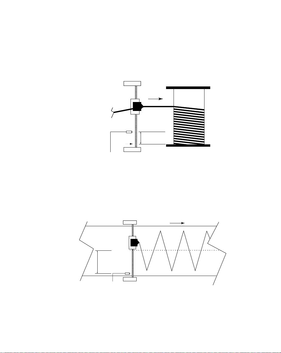
Home Offset (CP-31)
Sensor
LINE FLOW
FOLLOWER
LEAD
Home
C
L
Center Based
Home Offset
(CP-31)
The Home Offset parameter allows you to offset the “Home” position
and relocate it somewhere other than the sensor.
If CP-24 is set at “1” (edge based), measure the distance from the
sensor to the desired position of “Home”. Enter that E.U. amount in
CP-31.
LEAD
Sensor
Home
FOLLOWER
DIRECTION
OF WIND
Edge Based
Home Offset
(CP-31)
If CP-24 is set at “2” (center based), measure the distance from the
sensor to the center. Enter that E.U. amount in CP-31. The
M-Traverse will make a transparent, internal calculation and position
“Home” at a distance that is CP-31 minus 1/2 of the traverse length.
The position of “Home” will change to correspond with any changes in
the traverse length.
3 - 22
NOTE: Since the “Home” position calculations are dependent on the
Traverse Length (CP-02, CP-04, CP-06, CP-08) parameter and the Engineering Units (CP-15) parameter, those values must have already been entered
prior to entering a value in CP-31. To enter these parameters, refer to the
Operations: Control Parameters
section.
Page 70
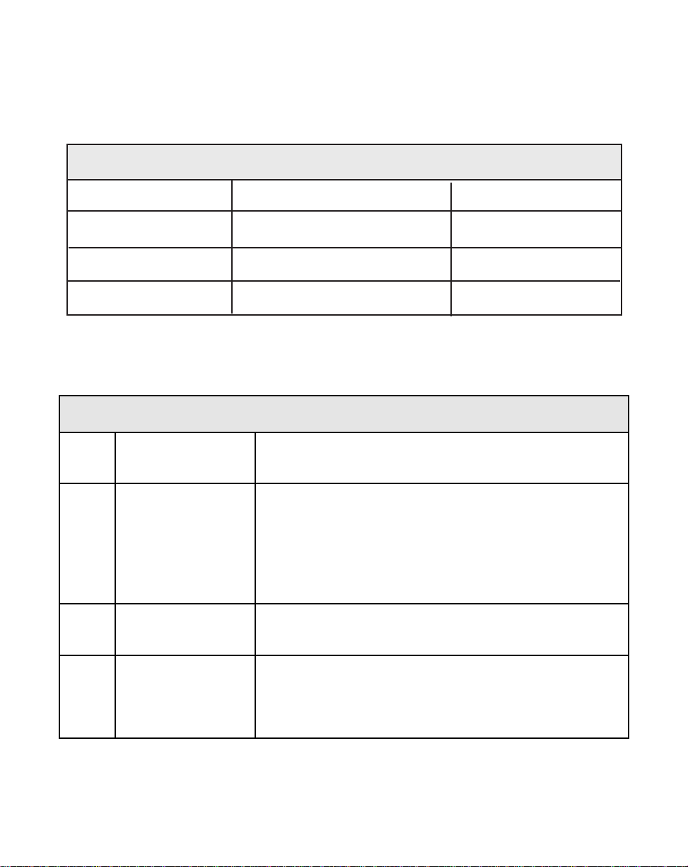
Table 3-14 Default Control Parameters for Changes
CP Parameter Name Parameter Value
CP-24 Edge/Center Based 1
CP-25 Change Activation 1
CP-30 At-Home Band 4
CP-31 Home Offset 0
Table 3-15 Entering Control Parameters for Changes
CP Parameter Name Parameter Value
CP-24 Edge/Center Based Enter “1” for an edge based profile.
Enter “2” for a center based profile.
CP-25 Change Activation When CP-24 is set to “1” (edge based), then:
Enter “1” to activate changes when the Follower is in
the “Home position.
Enter “2” to activate changes immediately.
Enter “3” to activate changes when the Follower is in
the end dwell position.
CP-30 At-Home Band Enter the number of encoder lines that you want to
allow on either side of the “0” Home Set position.
CP-31 Home Offset If CP-24 is set at “1” (edge based), enter the distance
from the sensor to the desired position of “Home”.
If CP-24 is set at “2” (center based), enter the distance
from the sensor to the center of the web.
3 - 23
Page 71
The Resume Enable parameter allows you to specify the conditions under which you
resume operation.
Resume Enable (CP-32)
If you interrupt the operation (F-Stop), the Resume Enable (CP-32)
parameter allows you to keep track of error in both the Follower and
Lead positions. It also allows you to freeze the Lead position and keep
track of error in the Follower position. The M-Traverse will adjust for the
error when you resume operation.
Resume is disabled by entering "1" in CP-32.
To keep track of error in both the Follower and Lead positions enter "2"
in CP-32.
To freeze the Lead position and keep track of error in the Follower
position, enter “3” in CP-32.
Both the Follower and the Lead information is saved at power-down. If
there has been no change in the mechanical position at power-down,
then the profile can be resumed at power-up.
If the mechanical position has changed and you resume operation, the
Follower could make an abrupt shift to resolve the position error. This
can severely injure you or damage the equipment. The specific consequences of this abrupt shift can vary, depending on your use of the
equipment and your system's design. Install safety equipment that is
appropriate for your application.
The factory default for the Resume Enable Control Parameter is found in Table 3-16.
To modify the default parameter refer to Table 3-17. If you are uncertain how to enter a
Control Parameter, review the
Operations: Keypad
section.
DANGER
When you resume operation
the Follower could make an
abrupt shift.
This can cause severe injury or
damage equipment.
Install safety equipment that is
appropriate for your application.
3 - 24
Page 72
Table 3-16 Default Resume Enable Control Parameter
CP Parameter Name Parameter Value
CP-32 Resume Enable 1
Table 3-17 Entering Resume Enable Control Parameters
CP Parameter Name Parameter Value
CP-32 Resume Enable Enter "1" disable resume.
Enter "2" to enable (Lead & Follower
position tracking)
Enter "3" to enable (Follower position
tracking)
3 - 25
Page 73
The polarity type and direction are determined by the following Control Parameters:
Home Sync Polarity (CP-35)
The Home Sync Polarity (CP-35) parameter allows you to choose
between rising edge polarity (positive going signal) or falling edge
polarity (negative going signal) during "Home Seek". This feature is
extremely useful when you use reflective or transmissive optical
sensors for the Home sensor. Enter "1" in CP-35 for a rising edge, or
"2" for a falling edge. Refer to the diagram below.
Rising Edge
+ Vdc
0 Vdc
/
Forward/Reverse Limit Polarity (CP-36)
The Forward/Reverse Polarity Limit (CP-36) parameter allows you to
choose between rising edge polarity (positive going signal) or falling
edge polarity (negative going signal) so that the Follower mechanism
will not travel beyond the traverse length limit. This feature is extremely useful when you use reflective or transmissive optical sensors
for the Home sensor. Enter "1" in CP-35 for a rising edge, or "2" for a
falling edge.
The factory default for the Polarity Control Parameters are found in Table 3-18. To
modify the default parameters refer to Table 3-19. If you are uncertain how to enter a
Control Parameter, review the
Operations: Keypad
Falling Edge
section.
+ Vdc
0 Vdc
/
3 - 26
Page 74

Table 3-18 Default Polarity Control Parameters
CP Parameter Name Parameter Value
CP-35 Home Sync Polarity 1
CP-36 Fwd/Rev Limit Polarity 2
Table 3-19 Entering Polarity Control Parameters
CP Parameter Name Parameter Value
CP-35 Home Sync Polarity Enter “1” for Rising Edge
Enter “2” for Falling Edge
CP-36 Fwd/Rev Limit Polarity Enter “1” for Rising Edge
Enter “2” for Falling Edge
3 - 27
Page 75

How the Forward Limit functions is determined by the following Control Parameter:
Forward Limit Format (CP-37)
Use the Forward Limit Format (CP-37) parameter to determine how the
Forward Limit will function during “Run”. If you set CP-37 to "1", then
the M–Traverse will engage “F-Stop” when the Forward Limit is encountered during “Run”. However, if you want the M–Traverse to terminate
the Constant Pitch Plateau, decelerate to zero speed, process the
Forward End Dwell and then begin the reverse profile back to “Home”
when the Forward Limit is encountered, then set CP-37 to "2".
Table 3-20 Default Polarity Control Parameters
CP Parameter Name Parameter Value
CP-37 Forward Limit Format 1
3 - 28
Table 3-21 Entering Polarity Control Parameters
CP Parameter Name Parameter Value
CP-37 Foward Limit Format Enter “1” to engage ”F-Stop”.
Enter “2” to terminate the
Constant Pitch Plateau,
decelerate to zero, process
the dwell and begin the
reverse profile.
Page 76

DIRECT MODE
The Direct mode is used to calibrate and troubleshoot the M-Traverse. In the Direct
mode of operation, you can set the level of the Speed Command Out directly from the
M-Traverse to the motor drive. The Direct mode is an open-loop mode of operation.
Therefore, Scaling, Accel/Decel, and closed loop compensation (PI) algorithms are
bypassed in the Direct mode. The Direct mode is used in conjunction with the Run and
the Stop controls.
Caution: To avoid damage to your system, the M-Traverse must be calibrated and the
motor drive set up before you enter the Direct mode. Refer to
Setup: Calibration.
The Direct Analog Command (CP-62) parameter uses the full 12 bit resolution of the
analog Speed Command Output.
A value of 4095 is a 100% forward output command.
A value of 2048 is a 50% forward output command.
0 is a zero output command.
A negative value indicates a reverse output command (e.g., - 4095 is a 100% reverse
command).
To enable the Direct mode, enter "2" the Control Mode (CP-14) parameter.
The factory default Direct Mode Control Parameters are found in Table 3-20. To modify
the default parameters, refer to Table 3-21. If you are uncertain how to enter a Control
Parameter, review the
Operations: Keypad
section.
Installation/
Table 3-22 Default Direct Mode Control Parameters
CP Parameter Name Parameter Value
CP-62 Direct Analog Command 0
CP-14 Control Mode 1
Table 3-23 Entering Direct Mode Control Parameters
CP Parameter Name Parameter Value
CP-62 Direct Analog Cmd Enter the DAC bits of the calitrated full scale
Speed Command Out at which you want your
system to operate.
CP-14 Control Mode Enter “2” to enable the Direct Mode (disables
both Follower Mode options).
3 - 29
Page 77

JOG
When you activate Jog, the RPM increase at the acceleration rate that you specified in
the Accel/Decel (CP-60) parameter until the Jog Setpoint (CP-61) is achieved. Jog can
only be entered from F-Stop and when Jog is terminated, the Follower mechanism
returns to F-Stop. Jog is used when you need brief bursts of speed to align the
Follower mechanism.
The factory default Jog Control Parameters are found in Table 3-22. To modify these
default parameters, refer to Table 3-23. If you are uncertain how to enter a Control
Parameter, review the
CP Parameter Name Parameter Value
CP-61 Jog Setpoint 50
CP-60 Accel/Decel 5.0
Operations: Keypad
Table 3-24 Default Jog Control Parameters
section.
Table 3-25 Entering Jog Control Parameters
CP Parameter Name Parameter Value
CP-61 Jog Setpoint Enter the RPM at which you want your system to
operate when it is in Jog.
CP-60 Accel/Decel Enter the number of seconds in which you want your
system to accelerate from zero RPM to the Jog Setpoint
speed.
3 - 30
Page 78

—NOTES—
3 - 31
Page 79

TUNING
If your system is unstable, or the position error is unacceptable, tuning may stabilize
your system or reduce the position error differences between the setpoint and
feedback. You can achieve a stable system using conservative values in the Tuning
Control parameters, however the position error may be unacceptable. On the other
hand, aggressive values in the Tuning Control parameters may cause the system to
become unstable. The goal is to reduce the position error to the level that you want, yet
maintain the system's stability.
To achieve an acceptable level of position error, increase the Gain (CP-65) parameter
until the system becomes unstable then reduce the CP-65 incrementally until the
system stabilizes. In systems that require greater accuracy, it may be necessary to
adjust the Integral (CP-66) parameter to reduce any remaining position error. In
systems with low inertia, the position error will be reduced more quickly if you enter
higher values in CP-66. An entry that is too high, however, can create instability or
overshoot the setpoint before reaching the correct value. Generally, use lower entries
for CP-66 on systems with a large inertia.
The M-Traverse comes factory pre-loaded with a complete set of default Tuning
parameters. These default settings are suitable for most applications.
The factory defaults for the Follower Tuning Control Parameters are found in Table 3-
24. To modify the default parameters refer to Table 3-25. If you are uncertain how to
enter a Control Parameter, review the
Operations: Keypad
section.
3 - 32
Table 3-26 Default Tuning Control Parameters
CP Parameter Name Parameter Value
CP-65 Gain 3000
CP-66 Integral 1
Page 80

Table 3-27 Entering Tuning Control Parameters
CP Parameter Name Parameter Value
CP-65 Gain With Integral (CP-66) set to “0” , increase the Gain
parameter value until the system becomes unstable,
then decrease it slightly until the system stabilizes.
Larger values will increase Gain. To verify the stability
of the speed changes, you can access Tach through
either the Tach key or the Tach (MV-40) parameter.
CP-66 Integral While switching between the high and low setpoints,
increase the Integral's default value of “1” until the
position error is reduced within an acceptable time
frame. To verify the stability of the speed changes, you
can access Tach through either the Tach key or the
Tach (MV-40) parameter.
3 - 33
Page 81

OUTPUT CONTROL
Output Control is influenced by the Batch Control Parameters, the Alarm Output, the
At-Home output and Outputs A and B. These parameters and outputs are discussed as
follows:
The Batch Control Parameters allow you to make a specific amount of product and
then automatically stop when that amount is reached.
Batch Format (CP-26)
Use the Batch Format (CP-26) parameter to indicate which type of
count that you want the Batch Counter to do. You can count either
Follower traverses or Lead reel revolutions. Enter “1” in CP-26 to count
the Follower traverses. Enter “2” in CP-26 to count Lead revolutions.
Batch Limit (CP-27)
The Batch Counter is an up-counter that is cleared to zero by the Batch
Reset input. Use the Batch Done Output to shut off the system when
the Batch Count has been reached. You can count either the number of
Follower traverses or the number of Lead reel revolutions. If you count
Follower traverses, each direction counts as one traverse. If you count
Lead revolutions, each wrap of the reel (or layer), is one lead revolution. Enter the total number that you want counted in Batch Limit (CP-
27).
Batch PreAct Distance (CP-28)
The Batch PreAct Distance (CP-28) parameter is used only if the Batch
Format (CP-26) has been set to number “1” (Follower traverses). CP28 allows you to set a specific distance at which to activate the Batch
Done. This can be at the end dwell or any distance from dwell, up to
the Accel/Decel Length at the opposite end from dwell. If you enter a
number that would go beyond the Accel/Decel Length, the M-Traverse
will automatically default to the Accel/Decel Length. For example, your
reel is 10 inches long, with an Accel /Decel Length of 1 inch on each
end, and the laypitch profile is 8 inches. CP-28 will default at 9 inches
for any amount above 9 inches that you enter in CP-28, because the
opposite Accel /Decel is 9 inches from the dwell. See the diagram
below for a profile representation of this example:
3 - 34
Laypitch
Accel/Decel
1" 8" 1"
9"
Accel/Decel
Dwell
Page 82
The factory defaults for the Batch Control Parameters are found in Table 3-26. To
modify the default parameters refer to Table 3-27. If you are uncertain how to enter a
Control Parameter, review the
Operations: Keypad
section.
Table 3-28 Default Batch Control Parameters
CP Parameter Name Parameter Value
CP-26 Batch Format 1
CP-27 Batch Limit 0
CP-28 Batch PreAct Distance 999999
Table 3-29 Entering Batch Control Parameters
CP Parameter Name Parameter Value
CP-26 Batch Format Enter “1” in CP-26 for Follower traverses.
Enter “2” in CP-26 for Lead reel revolutions.
CP-27 Batch Limit Enter the total number of Follower traverses or Lead
reel revolutions that you want counted.
CP-28 Batch PreAct Dist Enter a specific preact distance at which to activate the
Batch Done (only if CP-26 is set at “1”).
3 - 35
Page 83
The Alarm Output allows you to set a high speed RPM indication.
High Speed Alarm (CP-23)
Use the High Speed Alarm (CP-23) parameter to determine the RPM
level that will activate the High Speed Alarm Output. When the
Follower's motor RPM are at or above the value in CP-23, the High
Speed Alarm Output will activate.
The factory default for the Default Alarm Control Parameter is found in Table 3-28. To
modify the default parameter refer to Table 3-29. If you are uncertain how to enter a
Control Parameter, review the
Operations: Keypad
section.
Table 3-30 Default Alarm Control Parameter
CP Parameter Name Parameter Value
CP-23 High Speed Alarm 2000
Table 3-31 Entering Alarm Control Parameter
CP Parameter Name Parameter Value
CP-23 High Speed Alarm Enter the RPM limit that will activate the High Speed
Alarm Output.
3 - 36
Page 84
The At-Home Output activates in response to the At-Home Band parameter.
At-Home Band (CP-30)
When the Follower is within the At-Home Band, the At-Home Output
will be activated. The At-Home Band (CP-30) parameter allows for a
certain amount of “range” in the Home position, measured in encoder
lines. Although the Home Set input places home exactly at “0”, the AtHome Band (CP-30) allows home to be located in a band that is measured in negative and positive encoder lines on each side of the "0"
mark. The desired number of encoder lines is entered in CP-30.
NOTE: The Follower must be within the At-Home Band before “Run”
is entered. The Follower position must also be within the At-Home band
to activate the front panel At-Home LED indicator and the At-Home
discrete output.
The factory default for the At-Home Band Control Parameter is found in Table 3-30. To
modify the default parameter refer to Table 3-31. If you are uncertain how to enter a
Control Parameter, review the
Operations: Keypad
section.
Table 3-32 Default At-Home Band Control Parameter
CP Parameter Name Parameter Value
CP-30 At-Home Band 4
Table 3-33 Entering At-Home Band Control Parameter
CP Parameter Name Parameter Value
CP-30 At-Home Band Enter the number of encoder lines that you want to allow
on either side of the “0” Home Set position.
3 - 37
Page 85

Output A activates peripheral equipment in response to the Output A parameters. This
peripheral equipment can be set up to add material (e.g., adhesive or paint) during
specific segments of the Follower profile.
Output A Segment (CP-90)
Use the Output A Segment (CP-90) parameter to determine what
segment of the Follower profile will activate Output A.
Enter “1” in CP-90 to activate Output A during the constant pitch plateau
segment of the Follower profile.
Enter “2” in CP-90 to activate Output A during the constant pitch and
Accel/Decel segments of the Follower profile.
Enter “3” in CP-90 to activate Output A during the dwell segment of the
Follower profile.
The diagram below illustrates the segments of the Follower profile :
Follower Profile
Accel/Decel
Constant
Pitch
Plateau
Accel/Decel
Dwell
Output A Direction (CP-91)
Use the Output A Direction (CP-91) parameter to specify the direction in
which Output A will operate.
Enter “1” in CP-91 to activate Output A during the forward direction.
Enter “2” in CP-91 to activate Output A during the reverse direction.
Enter “3” in CP-91 to activate Output A during the forward and reverse
directions.
Output A Polarity (CP-92)
Use the Output A Polarity (CP-92) parameter to specify the voltage
polarity at which Output A will operate.
Enter “0” in CP-92 to activate Output A as Active Low Voltage Level.
Enter “1” in CP-92 to activate Output A as Active High Voltage Level.
3 - 38
1
2
3
Page 86
The factory defaults for the Output A Control Parameters are found in Table 3-32. To
modify the default parameters refer to Table 3-33. If you are uncertain how to enter a
Control Parameter, review the
Operations: Keypad
section.
Table 3-34 Default Control Parameters for Output A
CP Parameter Name Parameter Value
CP-90 Output A Segment 1
CP-91 Output A Direction 0
CP-92 Output A Polarity 0
Table 3-35 Entering Output A Control Parameters
CP Parameter Name Parameter Value
CP-90 Output A Segment Enter “1” to activate Output A during the constant pitch
plateau segment of the Follower profile.
Enter “2” to activate Output A during the constant pitch
plateau and Accel/Decel segment of the Follower profile.
Enter “3” to activate Output A during the Dwell
segment of the Follower profile.
CP-91 Output A Direction Enter “1” to activate Output A during the forward
direction.
Enter “2” to activate Output A during the reverse
direction.
Enter “3” to activate Output A during the forward and
reverse directions.
CP-92 Output A Polarity Enter “0” to activate Output A as Active Low Voltage
Level.
Enter “1” to activate Output A as Active High Voltage
Level.
3 - 39
Page 87
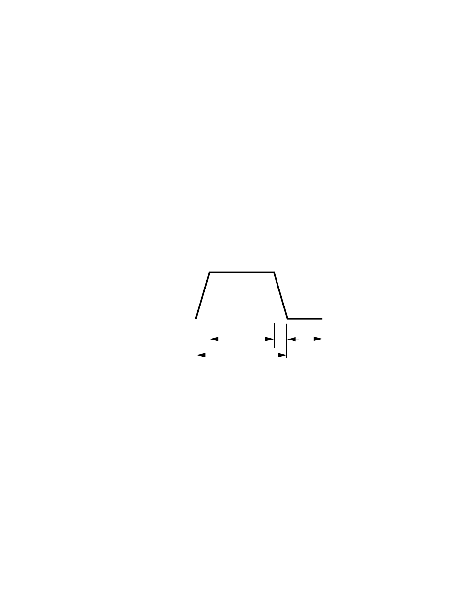
Output B activates peripheral equipment in response to the Output B parameters. This
peripheral equipment can be set up to add material (e.g., adhesive or paint) during
specific segments of the Follower profile.
Output B Segment (CP-93)
Use the Output B Segment (CP-93) parameter to determine what
segment of the Follower profile will activate Output B.
Enter “1” in CP-93 to activate Output B during the constant pitch plateau
segment of the Follower profile.
Enter “2” in CP-93 to activate Output B during the constant pitch plateau
and Accel/Decel segments of the Follower profile.
Enter “3” in CP-93 to activate Output B during the dwell segment of the
Follower profile.
The diagram below illustrates the segments of the Follower profile :
Follower Profile
Accel/Decel
Constant
Pitch
Plateau
Accel/Decel
Dwell
Output B Direction (CP-94)
Use the Output B Direction (CP-94) parameter to specify the direction in
which Output B will operate.
Enter “1” in CP-94 to activate Output B during the forward direction.
Enter “2” in CP-94 to activate Output B during the reverse direction.
Enter “3” in CP-94 to activate Output B during the forward and reverse
directions.
Output B Polarity (CP-95)
Use the Output B Polarity (CP-95) parameter to specify the voltage
polarity at which Output B will operate.
Enter “0” in CP-95 to activate Output B as Active Low Voltage Level.
Enter “1” in CP-95 to activate Output B as Active High Voltage Level.
3 - 40
1
2
3
Page 88
The factory defaults for the Output B Control Parameters are found in Table 3-34. To
modify the default parameters refer to Table 3-35. If you are uncertain how to enter a
Control Parameter, review the
Operations: Keypad
section.
Table 3-36 Default Control Parameters for Output B
CP Parameter Name Parameter Value
CP-93 Output B Segment 1
CP-94 Output B Direction 0
CP-95 Output B Polarity 0
Table 3-37 Entering Output B Control Parameters
CP Parameter Name Parameter Value
CP-93 Output B Segment Enter “1” to activate Output B during the constant pitch
plateau segment of the Follower profile.
Enter “2” to activate Output B during the constant pitch
plateau and Accel/Decel segment of the Follower profile.
Enter “3” to activate Output B during the Dwell
segment of the Follower profile.
CP-94 Output B Direction Enter “1” to activate Output B during the forward
direction.
Enter “2” to activate Output B during the reverse
direction.
Enter “3” to activate Output B during the forward and
reverse directions.
CP-95 Output B Polarity Enter “0” to activate Output B as Active Low Voltage
Level.
Enter “1” to activate Output B as Active High Voltage
Level.
3 - 41
Page 89

—NOTES—
3 - 42
Page 90

M–TRAVERSE OPERATION
The M–Traverse Operation section addresses the six modes that control the
M–Traverse's operation. This section explains the function of each of these modes and
how to use the modes for your specific system application. Diagrams are included to
illustrate the profile sequences.
The six modes are:
Follower Mode (Standard or Lay Adjusted)
Home Set
Home Seek
Home Return
Direct Mode
Jog
3 - 43
Page 91

FOLLOWER MODE (WEB SCANNING OR LEVEL WIND)
The M–Traverse is specifically designed for the precise control of reciprocating lead/
follower motion control applications. Its primary mode of operation is the Follower
mode. The Run input (J4, pins 6,7) activates the Follower mode when the following
conditions have already been established:
• The Control Mode (CP-14) is set to the Follower mode:
“1” for Standard.
“3” for Lay Adjusted.
• The M–Traverse is either in F-Stop or a position hold state.
• The Follower mechanism is within the At-Home Band (CP-30).
• MV-58 displays “0”, indicating that there is a valid Follower profile.
When the Follower mode has been activated, the Follower mechanism will begin to
move from “Home” in a forward direction (toward the Forward Limit). As the Follower
mechanism travels along the Traverse Length (CP-02, CP-04, CP-06, or CP-08), it
accelerates for the specified Accel/Decel Length (CP-09) then travels the constant pitch
plateau at the Process Ratio (MV-86). At the end of the constant pitch plateau, the
Follower mechanism decelerates the specified Accel/Decel Length (CP-09) to Dwell
(CP-10). The Follower mechanism remains at zero speed for the specified Dwell then
repeats the same profile in reverse. If the Wait input (J4, pins 7, 8) is shorted to
common (low) the Follower mechanism will pause at the closest end of the profile until
the Wait input is open (high). The Drive Enable discrete output is active during the
Follower mode.
Caution: To avoid damage to your system, the M–Traverse must be calibrated and the
motor drive set up before you enter the Follower mode. Refer to
Setup: Calibration.
The following diagram illustrates the Follower profile:
Follower/Lead
3 - 44
Process
Ratio
(MV-86)
Ratio
Accel/
Length
(CP-09)
Home
Sync
Sensor
Decel
Forward
Traverse Length
Constant Pitch
Plateau
Accel/
Decel
(CP-09)
Dwell
Dwell
(CP-10)
(CP-10)
Accel/
Decel
(CP-09)
Reverse
Traverse Length
Constant Pitch
Plateau
Installation/
Dwell
Accel/
(CP-10)
Decel
Length
(CP-09)
Page 92

HOME SET
Home Set is one of two ways in which you can establish “Home” (Home Seek is the
other way). When the Home Set input is closed, it sets the current position of the
Follower mechanism as “Home”. Home Set will establish “Home” at any arbitrary
position that you choose. You can use the Jog input to position the Follower
mechanism or you can position it manually.
Home Set enables the Drive Enable logic output, which allows the Follower mechanism
to hold its position at “Home” despite any outside force (such as gravity). The Home
Set is a momentary input that is edge triggered and is activated through the Home Set
input (J3, pin 14,16).
NOTE: “Home” must be established before the Follower mode can be used. “Home”
is identified by a Follower position of zero. In the Follower mode, “Home” is
the position from which the profile traverses in the Forward direction.
HOME SEEK
Home Seek also establishes “Home”. Home Seek finds and sets “Home” by locating
the Home Sync Sensor. When the Home Seek input is closed, the Follower
mechanism makes a profiled move at jog speed, until it aligns with the Home Sync
sensor, which then becomes “Home”.
Home Seek enables the Drive Enable logic output, which allows the Follower
mechanism to hold its position at “Home” despite any outside force (such as gravity).
Home Seek is a momentary input that is edge triggered and is activated through the
Home Seek input (J4, pin 1, 2). Home Seek is internally latched and does not need to
be maintained by an operator device.
NOTE: “Home” must be established before the Follower mode can be used. “Home”
is identified by a Follower position of zero. In the Follower mode, “Home” is
the position from which the profile traverses in the Forward direction.
Home Seek will always begin to move the Follower mechanism in the reverse direction
(towards the reverse limit). When Home Seek locates the Home Sync sensor, it
ramps down at the Accel/Decel rate (CP-60) to zero. This causes the Follower
mechanism to overshoot the Home Sync sensor and the M–Traverse compensates with
a triangulated forward Accel/Decel move that aligns the Follower mechanism with the
Home Sync sensor. There are a variety of profile possibilities, since Home Seek can
find home from any position on the traverse length. The following examples will
illustrate four possible Home Seek profiles.
3 - 45
Page 93

Example of an Edge Based Profile with no Home Offset.
Home Seek moves the Follower mechanism in the reverse direction (toward the
reverse limit). When Home Seek locates the Home Sync sensor, it ramps down at the
Accel/Decel (CP-60) rate to zero. This causes the Follower mechanism to overshoot
the Home Sync sensor and the M–Traverse compensates with a forward, triangulated
Accel/Decel move that aligns the Follower mechanism with the Home Sync sensor.
This profile is used in both web scan and level wind applications.
Reverse
Limit
(CP-60)
Accel/Decel
Home
Sync
Sensor
Jog Speed
(CP-61)
Forward
Limit
Accel/Decel
(CP-60)
Start Here
3 - 46
Page 94

Example of an Edge Based Profile with Home Offset.
Home Seek moves the Follower mechanism in the reverse direction, bypasses the
Home Sync sensor, and establishes “Home” at the Home Offset position. The Home
Offset position is measured in E.U.s and is the length away from the Home Sync sensor
that has been specified in the Home Offset (CP-31) parameter. When Home Seek
locates the Home Offset position, it ramps down at the Accel/Decel rate (CP-60) to
zero. This causes the Follower mechanism to overshoot the Home Offset position. The
M–Traverse compensates by continuing Home Seek in a forward, triangulated Accel/
Decel move that aligns the Follower mechanism with the Home Offset and establishes
“Home” . This profile is commonly used for applications that can not establish “Home”
at the Home Sync sensor because of interference (e.g., the physical edge of the reel or
a bracket that is in the way). This profile is used in both web scan and level wind
applications.
Reverse
Limit
(CP-60)
Accel/Decel
Home
Home
Offset
(CP-31)
Sensor
Home
Sync
Jog Speed
(CP-61)
Forward
Limit
Accel/Decel
(CP-60)
Start Here
3 - 47
Page 95

Example of a Center Based Profile with Home Offset.
Home Seek moves the Follower mechanism in the reverse direction, detects the Home
Sync sensor, then ramps down at the Accel/Decel rate (CP-60) to zero. Then the
M–Traverse makes a forward, triangulated move (in the forward direction) to the
“Home” position. The M–Traverse uses Home Sync as the starting point and
determines the “Home” position by subtracting is one-half of the Traverse Length from
Home Offset (CP-31).
Jog Speed
(CP-61)
Reverse
Limit
(CP-60)
AccelDecel
Home
Sync
Sensor
Home Offset
(CP-31)
1/2Traverse
Length
*
Home
(Subtract one-half traverse length from CP-31)
Forward
Limit
Accel/Decel
(CP-60)
Start Here
3 - 48
Page 96
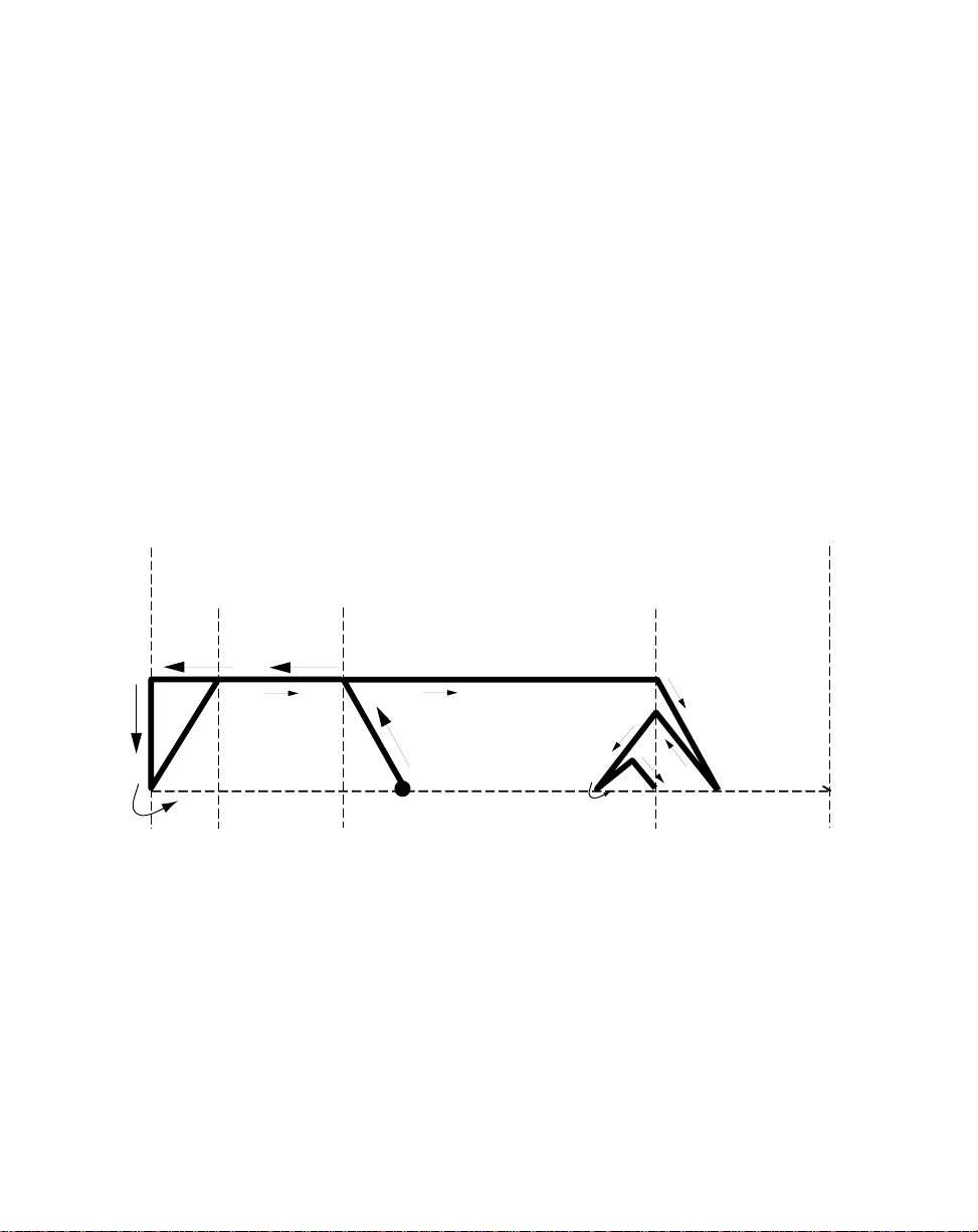
Example of an Edge Based Profile with Reverse Rebound.
Home Seek moves the Follower mechanism in the reverse direction. Home Seek
reaches the Reverse Limit without detecting the Home Sync sensor and immediately
stops. Home Seek moves the Follower mechanism in the forward direction (toward the
Forward Limit). When Home Seek locates the Home Sync sensor, it ramps down at
the Accel/Decel rate (CP-60) to zero. This causes the Follower mechanism to
overshoot the Home Sync sensor. The M–Traverse compensates by reactivating Home
Seek in the reverse direction, then a forward, triangulated Accel/Decel move that aligns
the Follower mechanism with the Home Sync senor. This profile is used in both web
scan and level wind applications.
Note : If Home Seek does not detect the Home Sync sensor by the time it reaches
the Forward Limit, the M–Traverse automatically shuts the system off (F-Stop).
Reverse
Limit
(CP-60)
Accel/Decel
Jog Speed
(CP-61)
accel/decel
(CP-60)
Forward
Limit
Accel/Decel
(CP-60)
Start Here
Home
Sync
Sensor
3 - 49
Page 97
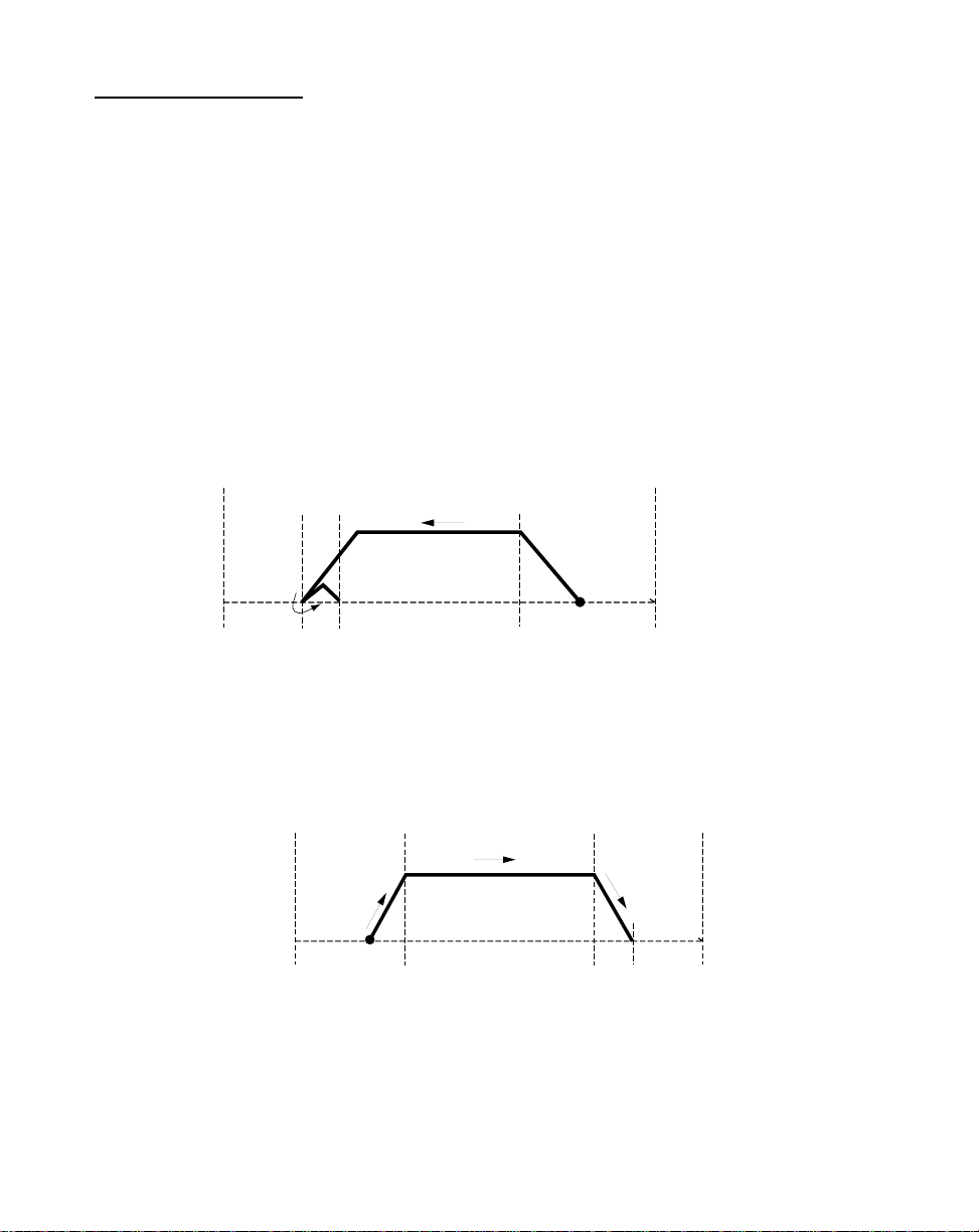
HOME RETURN
If “Home” has been established through either Home Set or Home Seek, then Home
Return can return the Follower mechanism to “Home”. When the Home Return input is
closed, the Follower mechanism makes a profiled move at jog speed until it aligns with
“Home”.
The Follower mechanism will move toward “Home”, in either the reverse or forward
direction, depending on which direction is closer to “Home”. When the Follower
mechanism travels in the reverse direction to locate “Home”, it ramps down at the
Accel/Decel rate (CP-60) to zero. This causes the Follower mechanism to overshoot
the Home Sync sensor by a distance that is equal to the At-Home Band (CP-30). The
M–Traverse compensates with a forward, triangulated Accel/Decel move that aligns the
Follower mechanism with “Home”.
Reverse
Limit
At-Home
Band
(CP-30)
Accel/Decel
(CP-60)
Jog Speed
(CP-61)
Accel/Decel
(CP-60)
Forward
Limit
Start Here
Home
Sync
Sensor
When the Follower mechanism travels in the forward direction to locate “Home”, it
decelerates directly down to the “Home” position from a predetermined position that
ramps the Follower directly to the “Home” position.
Reverse
Limit
(CP-60)
Accel/Decel
Start Here
Jog Speed
(CP-61)
Home
Sync
Sensor
Accel/Decel
(CP-60)
Forward
Limit
Home Return enables the Drive Enable logic output, which allows the Follower
mechanism to hold its position at “Home” despite any outside force (such as gravity).
The Home Return is a momentary input that is edge triggered and is activated through
the Home Return input (J4, pin 3, 4). Home Seek is internally latched and does not
need to be maintained by an operator device.
3 - 50
Page 98

DIRECT MODE
The Direct mode is used to calibrate and troubleshoot the M–Traverse. In the Direct
mode of operation, you can set the Speed Command Out from the M–Traverse that is
connected to the motor drive, directly. The Direct mode is an open-loop mode of
operation. Therefore, Scaling, Acceleration/Deceleration, and closed loop
compensation (PI) software are not involved in the Direct mode.
The Direct mode is used in conjunction with the Run and F-Stop controls. The Run
input (J4, pins 6,7) activates the Direct mode when the Control Mode (CP-14)
parameter has been set to “2” (enable Direct mode). When the Direct mode has been
activated, the analog output level goes immediately to the DAC bits specified in the
Direct Analog Command (CP-62). The Direct Analog Command (CP-62) parameter
uses the full 12 bit resolution of the analog Speed Command Output. A positive value
indicates a forward direction and a negative value indicates a reverse direction. The FStop input will move the Speed Command Out to zero immediately.
The Drive Enable logic output is active during Run and deactivated during F-Stop.
The Forward and Reverse Limits are also active. If the Follower mechanism
encounters a Forward or Reverse Limit, it will immediately stop (F-Stop) and go to zero
speed with no deceleration. The Follower mechanism can be moved away from either
limit by any control mode that move the Follower mechanism in the opposite direction
from the limit. All of the setpoint, Run and F-Stop changes will occur without the Accel/
Decel ramps.
Caution: To avoid damage to your system, the M–Traverse must be calibrated and the
motor drive set up before you enter the Direct mode. Refer to
Installation/
Setup: Calibration.
3 - 51
Page 99

JOG
Jog is used in conjunction with Home Set to move the Follower mechanism to “Home”.
Jog can also be used when you need brief bursts of speed to align the Follower
mechanism. When you activate Jog, the RPMs increase at the acceleration rate that
you specified in Acceleration/Deceleration (CP-60) until the Jog Setpoint (CP-61) is
achieved. When Jog is terminated, the RPMs return to zero immediately, with no
deceleration. The Jog direction is determined by the Jog Forward/Reverse Input (J4,
pins 15,16), which controls the direction of the Speed Command Output. The Drive
Enable logic output is active during the Jog mode.
Jog (J4, pins 16,17) is a maintained input. When the Jog input is closed, the M–
Traverse sends a Speed Command Out signal to the drive at the selected jog speed.
As a maintained input, Jog is only active when the operator device is closed.
3 - 52
Page 100

MONITOR VARIABLES
Parameters are divided into two classifications; Control Parameters (CP) and Monitor
Variable (MV). The numbered code that represents the parameter is the Parameter
Code. The operational data is the parameter's value.
Control Parameter 14 = 1
Parameters =
Monitor Variable 40 = 200
Parameter Code Parameter Value
This section is about Monitor Variables. Control Parameters are explained in
Operation: Control Parameters.
The M–Traverse has a number of Monitor Variables (MVs) that monitor the
performance of the M–Traverse and your system, help you troubleshoot for problems,
and confirm the wiring and tuning. MVs can be accessed at any time during the
M–Traverse's operation, including during Run, Jog, and F–Stop.
Note: Monitor Variables are status indicators only - you can not directly affect an MV.
There are four categories of Monitor Variables:
Input Monitoring
Output Monitoring
Performance Monitoring
Status Monitoring
In the sections that follow, the Monitor Variables are listed according to these
categories.
3 - 53
 Loading...