

Page 1

ML–Trim
User Manual
0001-0127
Revision C
i
Page 2

T echnical Assistance
If you have comments or questions concerning the operation of the ML–Trim, please
call us. A member of our Technical Support Staff will be happy to assist you. Ask for
Technical Support: (763) 424-7800 or 1-800-342-4411
Copyright © 1998 Contrex
ii
Contrex
®
8900 Zachary Lane North
Maple Grove, Minnesota 55369
Page 3
DANGER
Improper installation can
cause severe injury, death or
damage to your system.
Integrate this motion control
unit into your system with
caution.
Operate this motion control unit only under
the conditions prescribed in this manual.
Any other use shall be deemed
inappropriate.
Comply with the National Electrical Code
and all applicable local and national codes.
iii
Page 4

iv
Page 5

Table of Contents
Introduction ...................................................................... 1-1
Introducing the ML–Trim................................................................................ 1-3
Examples of ML–Trim Applications............................................................... 1-4
Installation / Setup ......................................................... 2-1
Mounting ........................................................................................................ 2-3
Wiring............................................................................................................ 2-5
Inputs.................................................................................................... 2-7
Outputs............................................................................................... 2-13
Serial Communications ...................................................................... 2-15
Calibration.................................................................................................... 2-17
Motor Drive Set Up............................................................................. 2-18
ML–Trim Calibration........................................................................... 2-19
Operation.......................................................................... 3-1
Keypad Operation.......................................................................................... 3-3
Keypad Lockout ............................................................................................. 3-5
Control Parameters........................................................................................ 3-7
Direct Mode.......................................................................................... 3-8
Master Mode ........................................................................................ 3-9
Follower Mode.................................................................................... 3-13
Inverse Master Mode ......................................................................... 3-22
Inverse Follower Mode....................................................................... 3-24
Acceleration/Deceleration .................................................................. 3-26
Tuning ................................................................................................. 3-27
Alarms ................................................................................................ 3-29
Jog...................................................................................................... 3-31
Logic Control................................................................................................ 3-33
Logic Inputs........................................................................................ 3-34
Logic Output....................................................................................... 3-37
Monitor Parameters ..................................................................................... 3-39
Input Monitoring ................................................................................. 3-40
Output Monitoring............................................................................... 3-42
v
Page 6

Performance Monitoring..................................................................... 3-43
Status Monitoring ............................................................................... 3-45
Serial Communications................................................................................ 3-49
Using Serial Communications............................................................ 3-50
Communications Software Design..................................................... 3-52
Troubleshooting.............................................................. 4-1
Diagnostics .................................................................................................... 4-3
Troubleshooting ........................................................................................... 4-11
PROM chip Replacement ............................................................................ 4-16
Glossary..............................................................Glossary-1
Glossary.............................................................................................Glossary-3
Appendices ......................................................................A-1
Appendix A: ML–Trim Specifications ............................................................ A-1
Appendix B: Formulas ..................................................................................B-1
Appendix C: Parameter Summary - numeric quick reference......................C-1
Appendix D: Control Parameter Reference..................................................D-1
Appendix E: Monitor Parameter Reference..................................................E-1
Appendix F: ML–Trim Fax Cover Sheet ....................................................... F-1
Appendix G: Wiring Diagram Examples ...................................................... G-1
Appendix H: Revision Log ............................................................................H-1
Warranty ..............................................................Warranty-1
Service Policy ....................................................................................Warranty-3
Warranty.............................................................................................Warranty-4
Index .......................................................................... Index-1
Index ....................................................................................................... Index-3
vi
Page 7

List of Illustrations
Figure 1-1 ML–Trim Master Mode ............................................................. 1-4
Figure 1-2 ML–Trim Follower Mode ........................................................... 1-5
Figure 2-1 ML–Trim Cutout Dimensions and Mounting Guide .................. 2-2
Figure 2-2 ML–Trim General Wiring Guide ............................................... 2-4
Figure 2-3 I/O Power (Isolated).................................................................. 2-7
Figure 2-4 I/O Power (Non-Isolated) .......................................................... 2-7
Figure 2-5 AC Power.................................................................................. 2-8
Figure 2-6 Lead Frequency ....................................................................... 2-8
Figure 2-7 Feedback Frequency ............................................................... 2-9
Figure 2-8 Run ........................................................................................... 2-9
Figure 2-9 Jog .......................................................................................... 2-10
Figure 2-10 R–Stop .................................................................................... 2-10
Figure 2-11 F–Stop .................................................................................... 2-11
Figure 2-12 Master or Follower .................................................................. 2-11
Figure 2-13 Setpoint Select........................................................................ 2-12
Figure 2-14 Speed Command Out ............................................................. 2-13
Figure 2-15 Drive Enable and Alarms Outputs .......................................... 2-14
Figure 2-16 ML–Trim Multidrop Installation................................................ 2-15
Figure 2-17 ML–Trim Serial Communications Connections .................... 2-16
Figure 3-1 ML–Trim Front Panel ............................................................... 3-4
Figure 3-2 ML–Trim Internal Structure .................................................... 3-43
Figure 4-1 Motor Does Not Stop Flowchart ............................................ 4-12
Figure 4-2 Motor Does Not Run Flowchart ............................................. 4-13
Figure 4-3 Motor Runs at Wrong Speed Flowchart ................................ 4-14
Figure 4-4 Motor Runs Unstable Flowchart ............................................ 4-15
Figure 4-5 PROM Location ...................................................................... 4-17
Figure G-1 ML–Trim Wiring Connections without Relays ........................ G-1
Figure G-2 Relay Start/Stop Wiring Connections .................................... G-2
Figure G-3 Start/Stop for Regen with Armature Contactor ...................... G-3
Figure G-4 Start/Stop for Non-Regen with Armature Contactor .............. G-4
Figure G-5 Two Channel Start/Stop - Lead/Follower Logic ..................... G-5
vii
Page 8

List of Tables
Table 3-1 Basic Keypad Entry ................................................................. 3-4
Table 3-2 Default Direct Mode Control Parameters ................................. 3-8
Table 3-3 Entering Direct Mode Control Parameters ............................... 3-8
Table 3-4 Default Master Scaling Control Parameters .......................... 3-10
Table 3-5 Entering Master Scaling Control Parameters ........................ 3-10
Table 3-6 Entering Master Setpoint Control Parameters ....................... 3-11
Table 3-7 Master Mode Control Parameters Example .......................... 3-12
Table 3-8 Default Follower Scaling Control Parameters ....................... 3-14
Table 3-9 Entering Follower Scaling Control Parameters ..................... 3-14
Table 3-10 Entering Follower Setpoint Control Parameters .................... 3-15
Table 3-11 Follower Mode Control Parameters Example A .................... 3-18
Table 3-12 Follower Mode Control Parameters Example B .................... 3-21
Table 3-13 Default Inverse Master Control Parameters........................... 3-22
Table 3-14 Entering Inverse Master Control Parameters......................... 3-22
Table 3-15 Inverse Master Mode Control Parameters Example .............. 3-23
Table 3-16 Default Inverse Follower Control Parameters ........................ 3-24
Table 3-17 Entering Inverse Follower Control Parameters ...................... 3-24
Table 3-18 Inverse Follower Mode Control Parameters Example............ 3-25
Table 3-19 Default Master or Follower Accel/Decel Control Parameters 3-26
Table 3-20 Entering Master or Follower Accel/Decel Control Parameters 3-26
Table 3-21 Default Master or Follower Tuning Control Parameters ........ 3-27
Table 3-22 Entering Master or Follower Tuning Control Parameters ...... 3-28
Table 3-23 Default Alarm Control Parameters ......................................... 3-29
Table 3-24 Entering Alarm Control Parameters ....................................... 3-30
Table 3-25 Default Jog Control Parameters ............................................ 3-31
Table 3-26 Entering Jog Control Parameters .......................................... 3-31
Table 3-27 Default Drive Enable Logic Control Parameters ....................3-37
Table 3-28 Entering Drive Enable Logic Control Parameters .................. 3-37
Table 3-29 Parameter Send - Host Transmission.....................................3-53
Table 3-30 Parameter Send - ML–Trim Response .................................. 3-56
Table 3-31 Control Command Send - Host Transmission ....................... 3-58
Table 3-32 Control Command Send - ML–Trim Response ...................... 3-60
Table 3-33 Data Inquiry - Host Transmission ........................................... 3-62
Table 3-34 Data Inquiry - ML–Trim Response ......................................... 3-64
Table 3-35 ASCII to Binary ...................................................................... 3-66
Table 3-36 Binary to Monitor Parameters ................................................ 3-67
viii
Page 9

Introduction
Introducing the ML–Trim
Examples of ML–Trim Applications
1 - 1
Page 10
1 - 2
Page 11

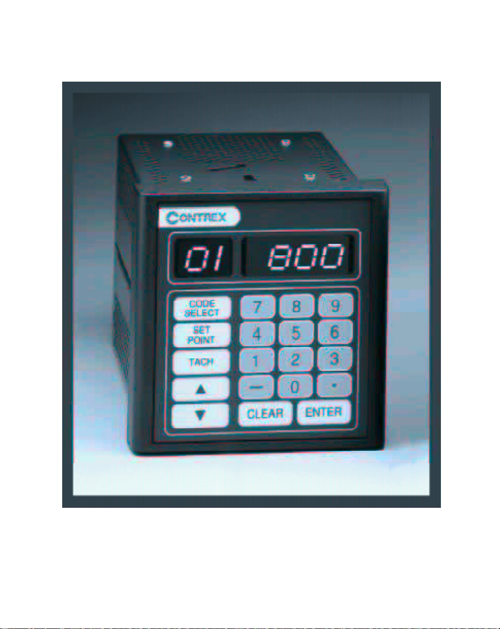
INTRODUCING THE ML–TRIM
The ML–Trim is a highly accurate, digital, motor controller. It has advanced embedded
software that is capable of solving a great variety of speed control tasks. It operates as
either a stand-alone control of a single motor (Master mode) or as a part of a complex
multi-drive system (Follower mode).
The ML–Trim is ideal for motor control applications where your present open loop or
rudimentary closed loop operations are inaccurate or where there is inadequate load
regulation. The ML–Trim adds accurate digital control to virtually any AC, DC, Servo,
Flux Vector or Clutch drives. The ML–Trim is also at the forefront in digitally accurate
Follower applications. See Figure 1-1 and Figure 1-2 for examples of Master and
Follower applications.
The ML–Trim is unique among its competition because the ML–Trim has preprogramed
software that integrates with your system with little effort from you. The ML–Trim will
also allow you to enter data that is unique to your system's specific needs (e.g.,
maximum RPMs, setpoints, acceleration/deceleration ramp rates). Using Control
Parameters (CPs), this data is entered through either the ML–Trim's integrated keypad
or though a host computer via the RS485 Serial Communications port. In addition to
the Control Parameters that allow you to customize for your systems specific needs, the
ML–Trim's Monitor Parameters (MPs) allow you to monitor your system's performance.
The ML–Trim's multiple scaling formats allow you to enter the setpoints and monitor
speed in the Engineering Units (e.g., RPMs, gallons per hour, feet per minute) that are
unique to your system. Among the ML–Trim's advanced capabilities is the flexibility to
preset up to four setpoint entries.
Integrating the ML–Trim's applied intelligence with your system puts precise speeds
and perfect synchronization at your fingertips, quickly, easily and cost effectively.
1 - 3
Page 12
EXAMPLES OF ML–TRIM
APPLICATIONS
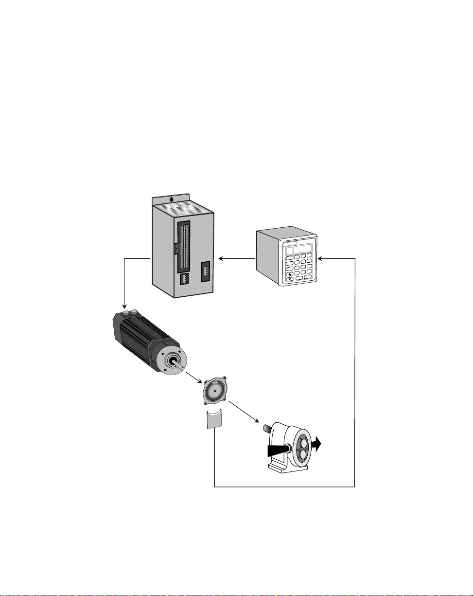
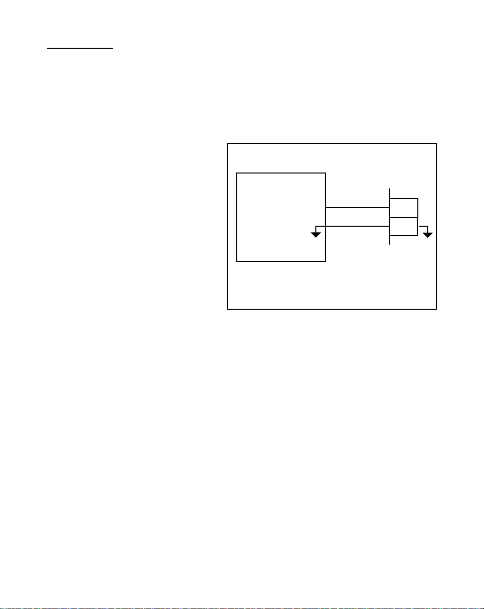
Figure 1-1 is an example of a Master mode of operation for a pump application. The
scaling format allows the operator to enter a setpoint in Engineering Units of gallons per
minute. The ML–Trim compares the sensor shaft feedback to the scaled setpoint and
calculates any speed error. When the ML–Trim finds speed error, the control algorithm
adjusts the Speed Command Out to the motor drive and reduces the error to zero.
Speed
Command
Out
ontrex
C
Motor Drive ML–Trim
Contrex
CODE
SELECT
POINT
TACH
SET
89
7
456
23
1
0
–
ENTER
CLEAR
.
1 - 4
Motor
Sensor
Pump
Feedback Frequency
Figure 1-1 ML–Trim Master Mode
Page 13
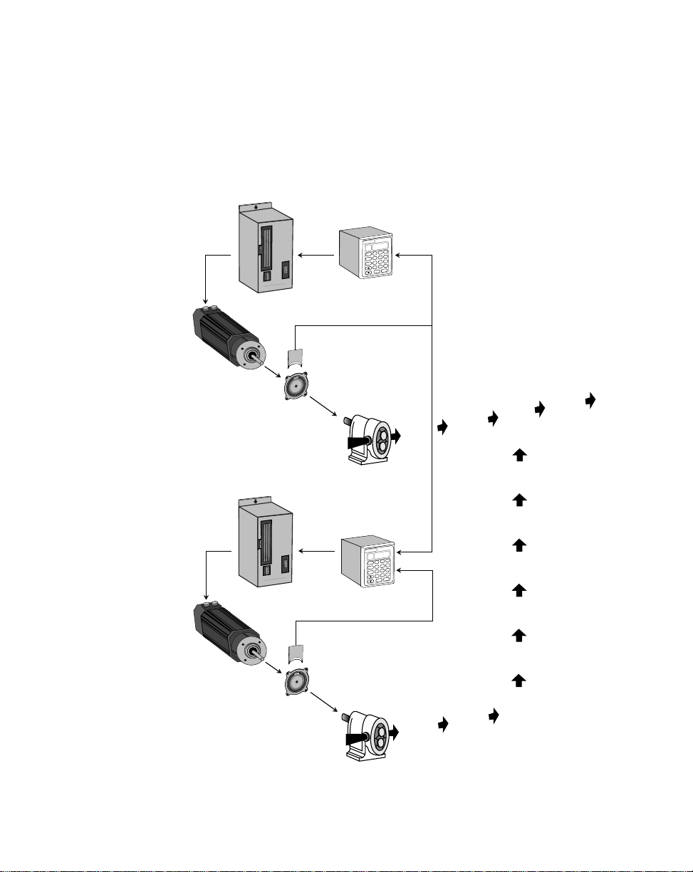
Figure 1-2 is an example of the Follower mode of operation in a pump application. The
scaling format allows the operator to enter the setpoint as a ratio of ingredient B to
ingredient A. The ML–Trim compares the setpoint ratio to the Follower sensor shaft
feedback and Lead sensor shaft feedback to calculate any speed error. When the
ML–Trim finds speed error, the control algorithm adjusts the Speed Command Out to
the motor drive and reduces the error to zero.
Lead
Speed
Lead Motor
Command
Out
ontrex
C
Motor Drive ML–Trim
Sensor
Pump
Contrex
8 9
7
CODE
SELECT
4 5 6
SET
POINT
2 3
1
TACH
.
0
–
ENTER
CLEAR
Feedback Frequency
Ingredient A
Final Product
Follower
Follower Motor
Lead Frequency
Contrex
8 9
7
CODE
SELECT
4 5 6
SET
POINT
2 3
1
TACH
.
0
–
ENTER
CLEAR
C
ontrex
Speed
Command
Out
Motor Drive ML–Trim
Feedback Frequency
Sensor
Pump
Ingredient B
Figure 1-2 ML–Trim Follower Mode
1 - 5
Page 14

—NOTES—
1 - 6
Page 15

Installation / Setup
Mounting
Wiring
Inputs
Outputs
Serial Communications
Calibration
Motor Drive Setup
ML–Trim Calibration
2 - 1
Page 16
Contrex
,
,
CUTOUT
(
3.65" .03"
6.00"
(
DOOR PANEL
Contrex
8 9
7
CODE
SELECT
4 5 6
SET
POINT
TACH
1
–
CLEAR
2 3
0
ENTER
.
)
3.60"
CUTOUT
(
3.65" .03"
3.60"
*
4.00"
*
From the rear of the door panel to the back of the connectors
4.00"
2 - 2
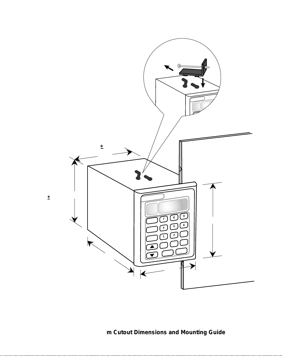
Figure 2-1 ML–Trim Cutout Dimensions and Mounting Guide
Page 17

MOUNTING
This section contains instructions for mounting the ML–Trim in the door panel of a
NEMA Industrial Electrical enclosure. The ML–Trim is packaged in a compact 1/4 DIN
Vertical Instrument Enclosure that mounts easily in the door of your Industrial Electrical
Enclosure. The Electrical Enclosure must have an IP54 rating or higher to comply with
CE installations.
To mount the ML–Trim:
1) The NEMA Industrial Electrical Enclosure that will house the ML–Trim must
conform to the following environmental conditions:
Temperature: 0 - 55 degrees C
(Internal NEMA enclosure temperature)
Humidity: 0 - 95% RH non-condensing
Environment: Pollution degree 2 macro - environment
Altitude: To 3300 feet (1000 meters)
NOTE: Allow adequate spacing between the ML–Trim and other equipment
to provide for proper heat convection. Placing the ML–Trim too close to
adjacent equipment could cause the interior ambient temperature to exceed
55 degrees C. Spacing requirements depend on air flow and enclosure
construction.
2) The dimensions for the door panel cutout are 3.65"+ .03" x 3.65 +.03"
(see Figure 2-1). Allow two inches of clearance on all sides of the cutout for
mounting clamp attachments, wire routing and heat convection.
3) Insert the ML–Trim through the door panel cutout until the gasket and bezel
are flush with the door panel (see Figure 2-1).
4) Slide the mounting clamps into the slots that are located on the top and
bottom of the ML–Trim. Tighten the mounting screws until the ML–Trim is
mounted securely in the NEMA Electrical Enclosure. Do not overtighten.
2 - 3
Page 18
*
Use 115 VAC with ML-Trim model # 3200-1931
Use 230 VAC with ML-Trim model # 3200-1932
L1
*
Neut or L2
GND/PE
RS485 Serial
Communications
5V_DI
COM
LEAD_FQ
FDBK_FQ
COM
RUN
JOG
COM
R–STOP
F–STOP
COM
MST / FOL
SETPT
COM
V_DO
DRV_EN
ALARM
COM
USE COPPER WIRE ONLY. SELECT WIRE SIZE
ACCORDING TO AMPACITY FOR 60/75 C WIRE ONLY.
TIGHTEN J3 TERMINALS TO 5 LB-INS.
J1 J4
J3
T / R +
T / R –
COM_AUX
RS485
COMM
AUX
PWR
L1
NEUT
GND
PE
AC
POWER
INC
MAX_SPD
SPD
CMD
DRV_SIG
DRV_COM
AC POWER
115 VAC
0.1 AMPS
50 / 60 HZ
I / O
PWR
FREQ
INPUTS
DIGITAL
INPUTS
J5
DIGITAL
OUTPUTS
5V
COM_AUX
J2
Run
Jog
R-Stop
F-Stop
Master/
Follower
Setpoint
Select
Lead
Frequency
Sensor
Feedback
Frequency
Sensor
+5VDC External
DC Power
Supply
+5V COM
+5V
SIG
COM
+5V
SIG
COM
50V
MAX
+V
COM
R1
R2
External
DC Power
Supply
TD/RD+
TD/RD–
COM
Motor Drive
SIG
COM
1
2
3
1
2
1
2
3
1
2
123456789
101112131415161718
Fuses
1A
250V
2 - 4
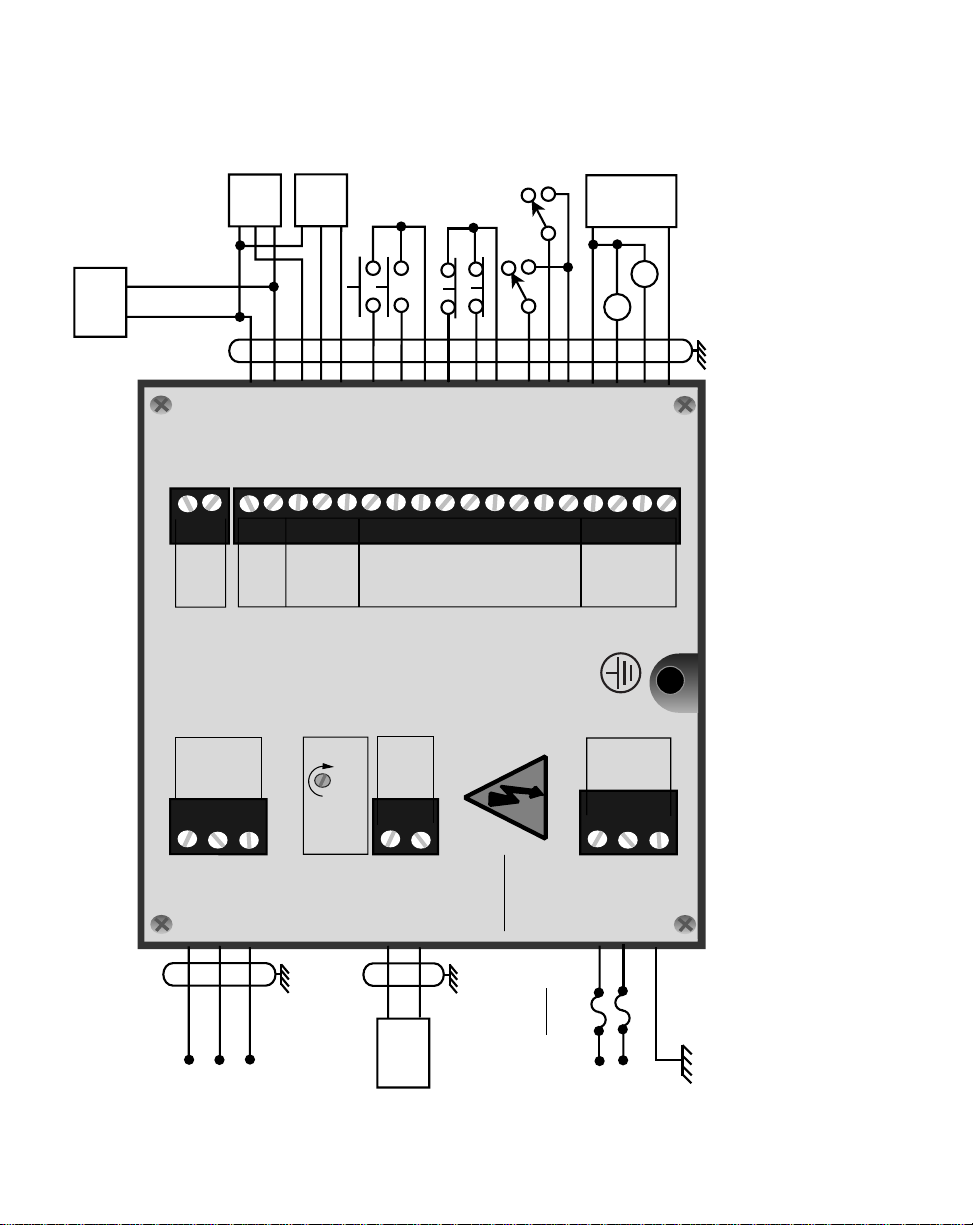
Figure 2-2 ML–Trim General Wiring
Page 19

WIRING
This section contains the input, output and serial communications wiring information for
the ML–Trim. Please read this section prior to wiring the ML–Trim to ensure that you
make the appropriate wiring decisions.
NOTE: The installation of this motor control must conform to area and local electrical
codes. See
National Fire Protection Association, or
Use local codes as applicable.
Use a minimum wire gauge of 18 AWG.
Use shielded cable to minimize equipment malfunctions from electrical noise.
Keep the AC power wiring (J3) physically separated from all other wiring on the
ML–Trim. Failure to do so could result in additional electrical noise and cause
the ML–Trim to malfunction.
A hand operated supply disconnect device must be installed in the final application. The primary disconnect device must meet EN requirements.
Inductive coils on relay, contactors, solenoids that are on the same AC power
line or housed in the same enclosure should be suppressed with an RC network across the coil. For the best results, use resistance (r) values of 50 ohms
and capacitance (c) values of 0.1 microfarads.
The National Electrical Code
The Canadian Electrical Code
(NEC,) Article 430 published by the
(CEC).
Install an AC line filter or isolation transformer to reduce excessive EMI noise,
such as line notches or spikes, on the AC power line.
DANGER
Hazardous voltages.
Can cause severe injury, death or
damage to the equipment.
The ML–Trim should only be
installed by a qualified
electrician.
2 - 5
Page 20

–NOTES—
2 - 6
Page 21
INPUTS
NOTE: The installation of this motor control must conform to area and local electrical
codes. See
National Fire Protection Association, or
Use local codes as applicable.
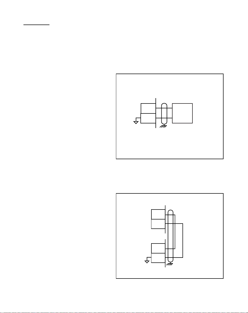
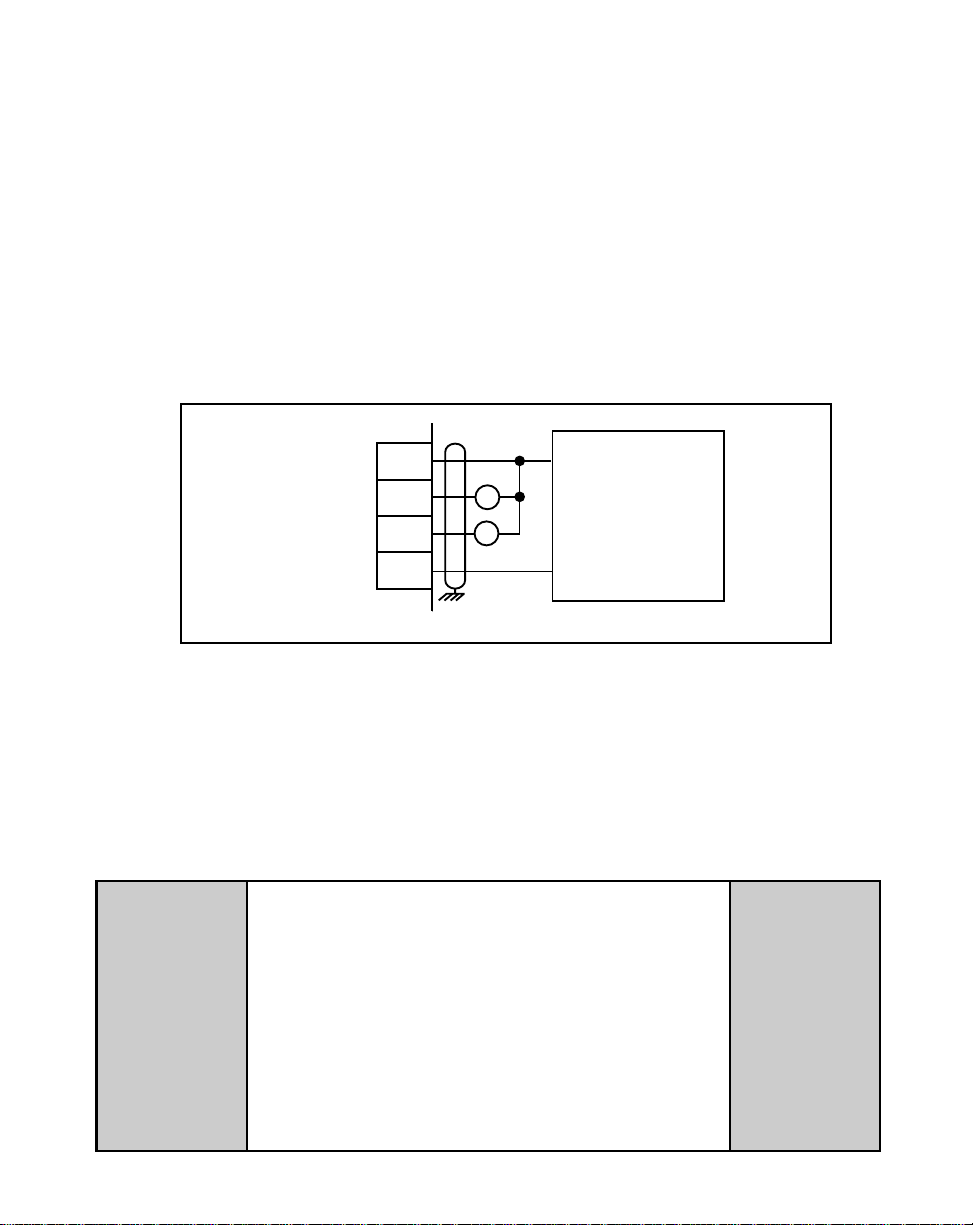
I/O Power (J5 pins 1, 2)
The National Electrical Code
The Canadian Electrical Code
(NEC,) Article 430 published by the
(CEC).
For isolated operations, the
Frequency Inputs (J5 pins 3, 4, 5),
the Digital Inputs (J5 pins 6-14 ) and
the Digital Outputs (J5 pins 15-18)
require an external source of
+5VDC power.
CAUTION: The ML-Trim is
shipped from the factory nonisolated with J4 and J5 jumpers.
You must remove the J4 and J5
jumpers before you connect the
External Power supply or you can
damage the equipment. Do not
exceed +5VDC on the I/O Power
Input.
Use the Auxiliary Power Output
(J4 pins 1, 2) to supply power to
non-isolated operations. The
ML-Trim is shipped from the factory
with the wiring defaulted to the nonisolated operation.
+5VDC MAXIMUM
1
2
J5
* Do not connect the External Power Supply
Common to Earth Ground.
+5V
COM
+5VDC
External
Power
Supply
Figure 2-3 I/O Power / Isolated
1
2
J4
+5V
COM_AUX
*
1
2
J5
Figure 2-4 I/O Power / Non-Isolated
2 - 7
Page 22
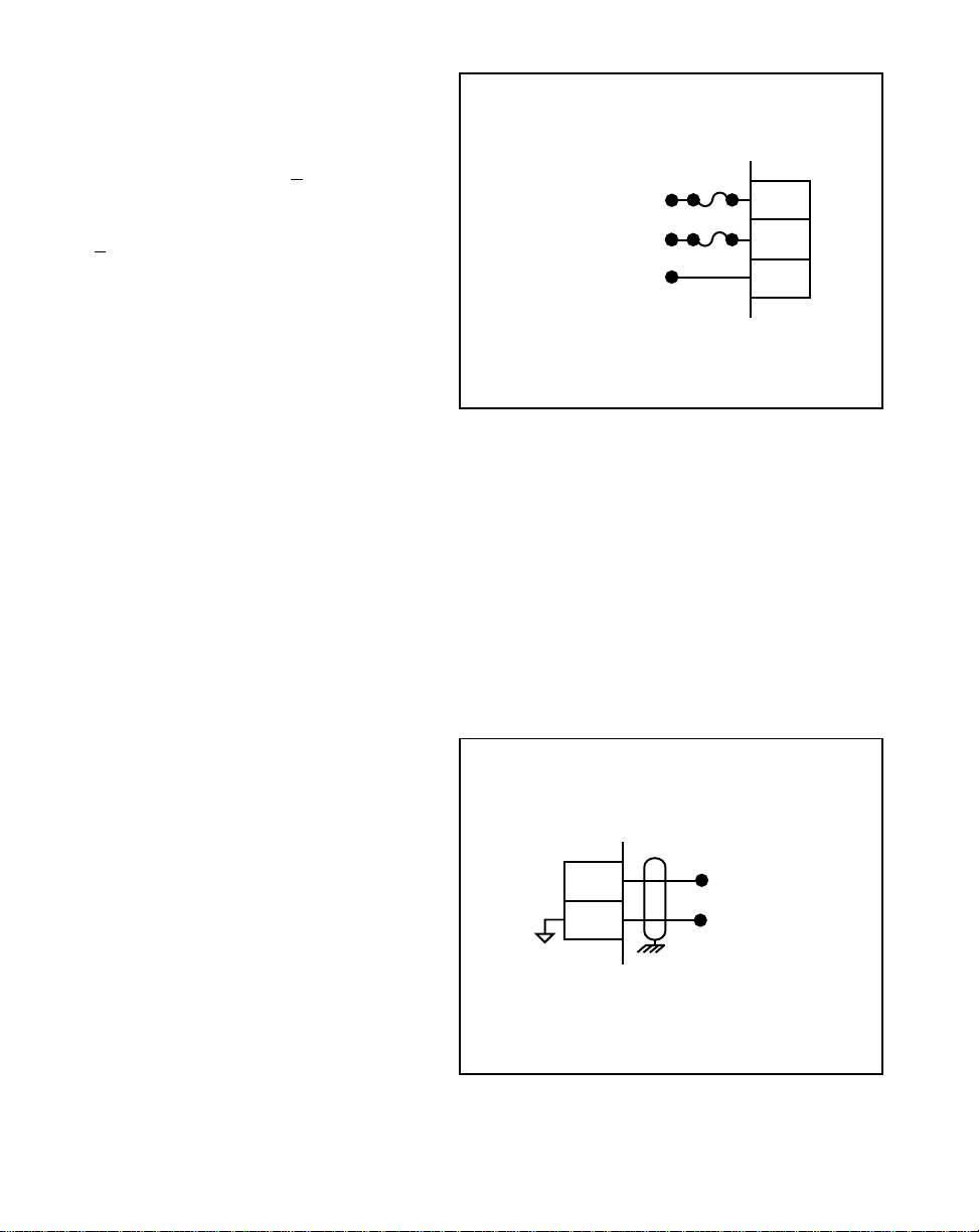
AC Power (J3 pins 1, 2, 3)
The ML–Trim model #3200-1931
operates on 115 VAC + 15%, 0.1
Amp., 50/60 Hz. The ML–Trim model
#3200-1932 operates on 230 VAC
+ 15%, 0.1 Amp., 50/60 Hz.
* Fuse L1 for 115VAC applications. Fuse L1 and L2 for
230VAC applications. Use
1 Amp 250V normal blow
fuses.
L1
Neutral or L2
GND/PE
*
*
Figure 2-5 Input Power
1
2
3
J3
Lead Frequency (J5 pins 3, 5)
The Lead Frequency is a pulse train
input that the ML–Trim uses to
determine the speed of the lead
motor. For signal level specifications,
refer to
ML–Trim Specifications,
2 - 8
References: Appendix A
page A-1
3
,
5
J5
Signal
Common
Figure 2-6 Lead Frequency
Page 23
Feedback Frequency
(J5 pins 4, 5)
The Feedback Frequency is a pulse
train input that the ML–Trim uses to
determine the speed of the follower
motor. For signal level specifications
refer to
ML–Trim Specifications,
References: Appendix A
page A-1.
If the Feedback Frequency is lost,
the ML-Trim will command a 100% Speed Out
and the motor will run at 100% capacity.
This can cause severe injury, death or
equipment damage.
,
Figure 2-7 Feedback Frequency
DANGER
4
5
J5
Signal
Common
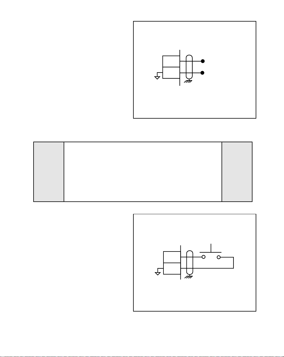
Run (J5 pins 6, 8)
When the Run input (J5 pin 6) is
momentarily shorted to common, the
ML–Trim enters Run. As a
momentary input, Run is internally
latched and does not need to be
maintained by an operator device.
NOTE: Close the R–Stop and F–Stop
inputs prior to entering Run.
If you are only using one of
the Stop inputs, wire short the
other Stop input to common
or the ML–Trim will not enter
“Run”.
RUN
6
8
J5
Figure 2-8 Run
2 - 9
Page 24
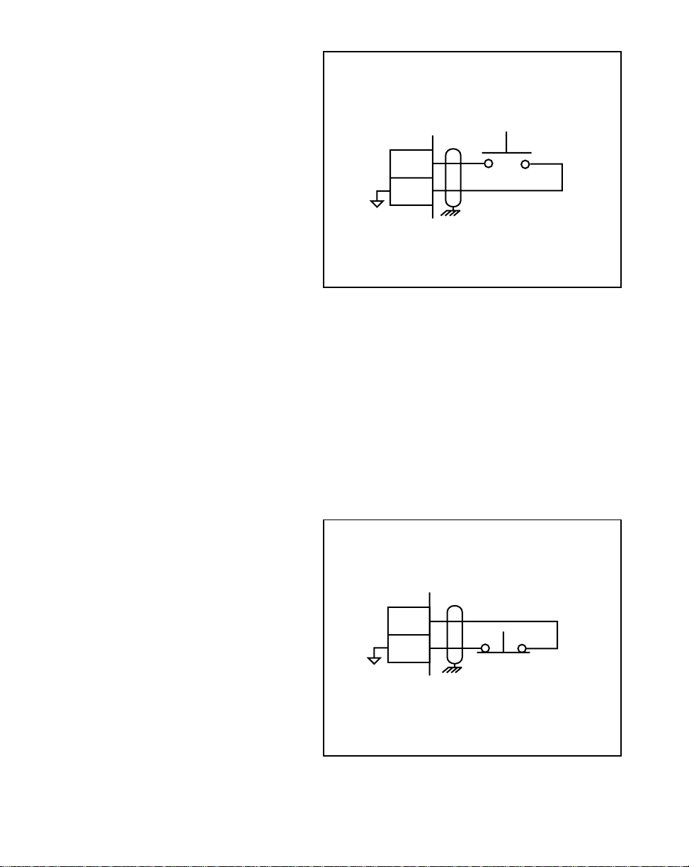
Jog (J5 pins 7, 8)
Jog is a maintained input. When Jog
is closed, the ML–Trim sends a
Speed Command Out signal to the
drive at the selected jog speed. As a
maintained input, Jog is only active
when the operator device is closed.
JOG
7
8
NOTE: Close the R–Stop and
F–Stop inputs and open the
Run input, prior to entering
Jog. If you are only using
one of the Stop inputs, wire
short the other Stop input to
common or the ML–Trim will
not enter Jog.
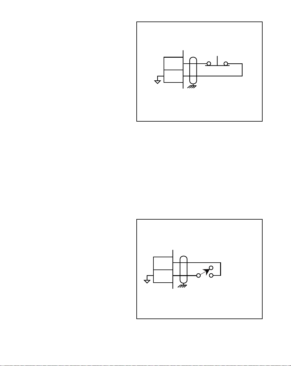
R–Stop (J5 pins 9, 11)
R–Stop is a momentary input. When
it is opened, the ML–Trim ramps to a
zero Speed Command Out at the
specified deceleration rate. As a
momentary input, R–Stop is internally
latched and does not need to be
maintained by an operator device.
J5
Figure 2-9 Jog
9
11
R-STOP
J5
2 - 10
Figure 2-10 R–Stop
Page 25
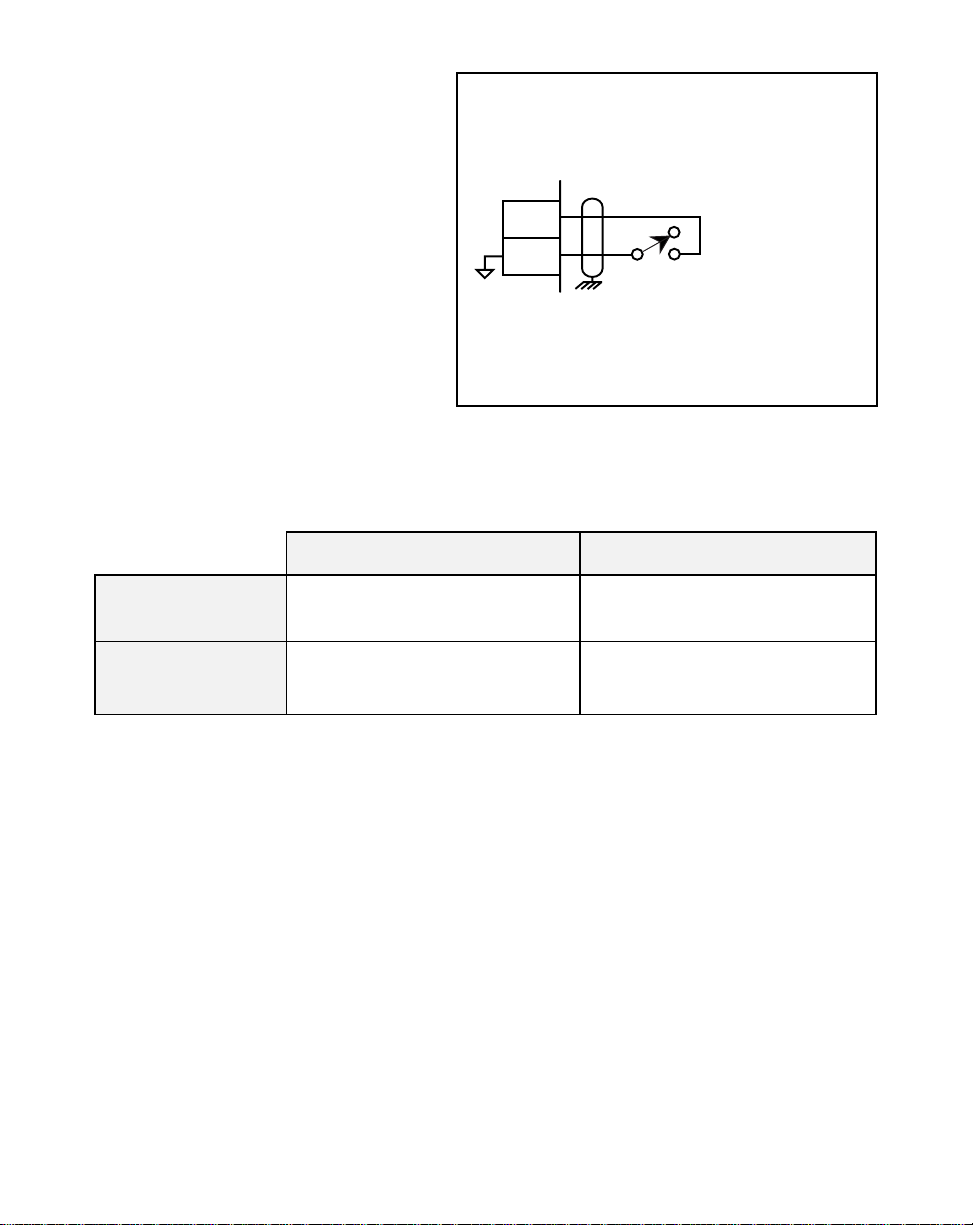
F-Stop (J5 pins 10, 11)
F-Stop is a momentary input. When
it is open, the ML–Trim stops
immediately (zero RPM) and ignores
the specified deceleration rate. As a
momentary input, F-Stop is internally
latched and does not need to be
maintained by an operator device.
F-STOP
10
11
J5
Figure 2-11 F–Stop
Master or Follower
(J5 pins 12, 14)
This input determines the ML–Trim's
mode of operation and resulting
scaling formula that the control
algorithm uses. The ML–Trim is in
Master mode when the circuit is
open, and Follower mode if the circuit
is shorted to the common.
12
14
J5
MASTER
FOLLOWER
Figure 2-12 Master / Follower
2 - 11
Page 26
Setpoint Select (J5 pins 13, 14)
The Master and Follower setpoints
are determined by the Setpoint Select
input combined with the Master/
Follower Input. For access to Master
Control Parameters 1 and 2 and
Follower Control Parameters 3 and 4,
refer to the chart below.
CONTROL
13
14
J5
PARAMETER 1 OR 3
CONTROL
PARAMETER 2 OR 4
Figure 2-13 Setpoint Select
Setpoint Select / Closed Setpoint Select / Open
Master/Follower
Input Open
Master/Follower
Input Closed
Master Control Parameter 1 Master Control Parameter 2
Follower Control Parameter 3
Follower Control Parameter 4
2 - 12
Page 27
OUTPUTS
NOTE: The installation of this motor control must conform to area and local electrical
codes. See
National Fire Protection Association, or
Use local codes as applicable.
Speed Command Out
(J2 pins 1, 2)
The National Electrical Code
The Canadian Electrical Code
(NEC,) Article 430 published by the
(CEC).
Speed Command Out is an isolated
analog output signal that is sent to
the motor drive to control the speed
of the motor. Wire the Speed
SIGNAL INPUT
*
DRIVE COMMON
Speed Command Out
Isolated Common
1
2
Command Out into the Speed Signal
Input of the drive. If the motor drive
has a potentiometer speed control,
remove the potentiometer
connections and wire the Speed
Command Output to the
MOTOR DRIVE
Do not connect the Drive Isolated Common to other
*
Logic Commons
J2
potentiometer wiper input. The
ML–Trim's isolated common should
Figure 2-14 Speed Command Out
always be connected to the drive
common.
Drive Enable (J5 pin 16)
The Drive Enable output is activated (driven low) when the ML–Trim is signaling a
nonzero speed command to the motor drive, as defined by Drive Enable Logic (CP-74)
The Drive Enable output is driven high (relay deactivated) after Power Up and during
R–Stop and F–Stop. See Figure 2-15. Refer to
Output,
page 3-37 for details.
Operations: Logic Control, Logic
NOTE: This is an open-collector relay driver. For specification details, see
Appendix A
-
ML–Trim Specifications,
page A-1. Use an external DC power
supply to power the relays. Free-wheeling diodes are incorporated internally in
the ML–Trim and do not need to be added externally.
References:
2 - 13
Page 28
Alarm (J5 pin 17)
By entering alarm Control Parameters, you can establish circumstances under which
the ML–Trim will alert you to potential operating problems. The alarm can be wired to
activate a warning light, a warning sound, or to shut down the system under specified
conditions. Alarm Format (CP-10) determines which alarm conditions will activate the
Alarm output, using the values that are entered in Low Alarm (CP-12), High Alarm
(CP-13), Ramped Error (CP-14) and Scaled Error (CP-15). See Figure 2-15. Refer to
Operations: Logic Control, Logic Output,
NOTE: This is an open-collector relay driver. Use an external DC power supply to
power the relays. Free-wheeling diodes are incorporated internally in the
ML–Trim and do not need to be added externally.
page 3-37 for details.
+V_DO
Drive Enable
Alarm
Common
15
16
17
18
J5
R1
R2
+
EXTERNAL
DC
POWER
SUPPLY
(50V Max)
–
Figure 2-15 Drive Enable and Alarm Outputs
Auxiliary DC Power (J4 pin 1, 2)
The 5 volt output (J4 pin 1) is a DC regulated output that can be used to power
encoders or other auxiliary equipment that is used in conjunction with the ML–Trim. If
this output is used, it will nullify optical isolation.
WARNING
Do not exceed
the maximum current output of
150 mA for +5 VDC.
2 - 14
Exceeding the maximum
current output
can damage the ML–Trim.
Page 29
SERIAL COMMUNICATIONS
NOTE: The installation of this motor control must conform to area and local electrical
codes. See
National Fire Protection Association, or
Use local codes as applicable.
The Serial Communications interface on the ML–Trim complies with EIA Standard
RS–485-A for balanced line transmissions. This interface allows the host computer to
perform remote computer parameter entry, status or performance monitoring, and
remote control of the ML–Trim. See
information on using Serial Communications. The ML-Trim is designed to use with an
isolated RS232 to RS485 converter.
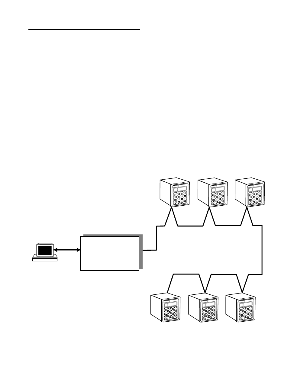
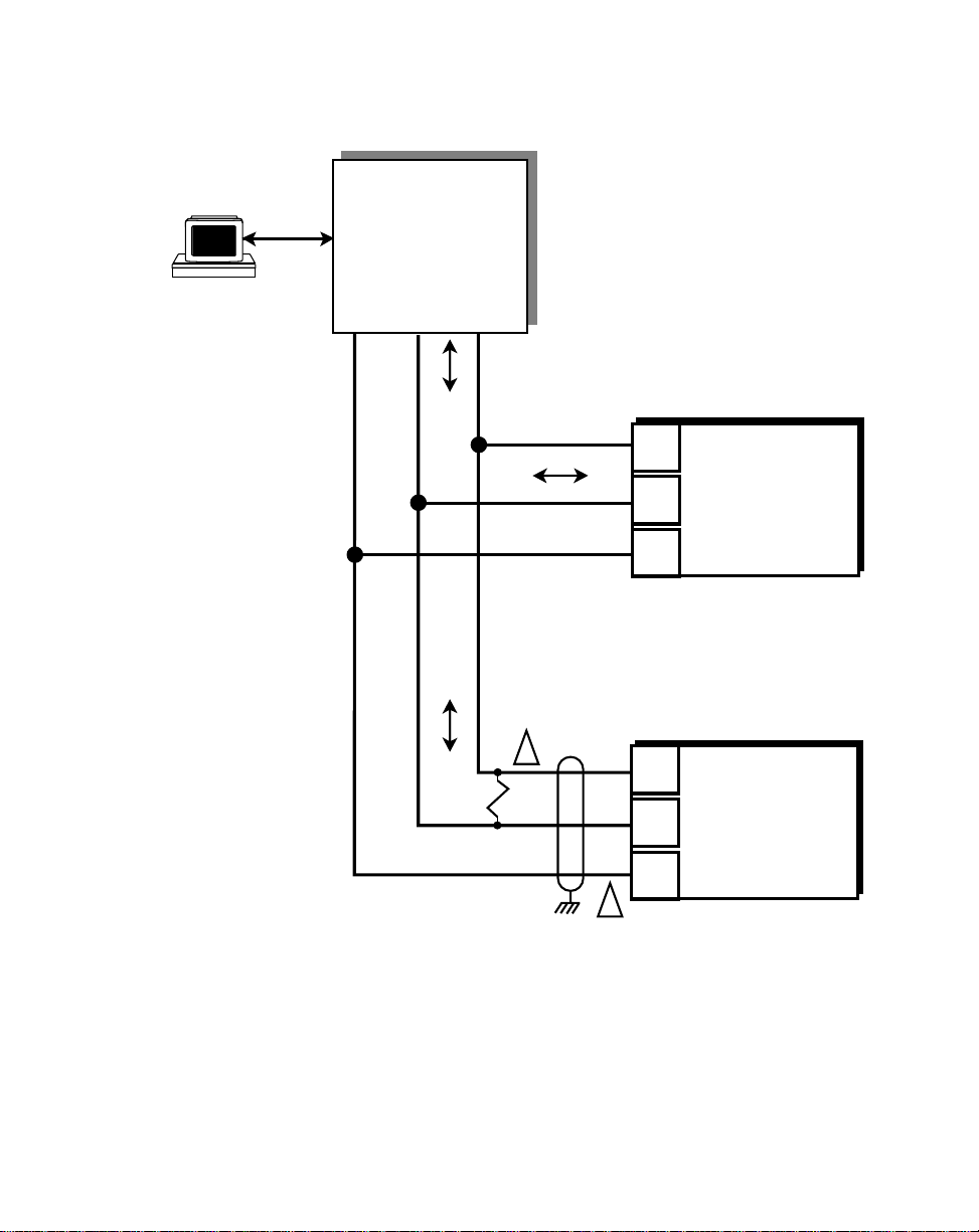
Figure 2-16 illustrates a multidrop installation of the Serial Communications link and
Figure 2-17 illustrates the Serial Communications connections.
The National Electrical Code
The Canadian Electrical Code
Operations: Serial Communications,
(NEC,) Article 430 published by the
(CEC).
page 3-49 for
Contrex
8 9
7
CODE
SELECT
4 5 6
SET
POINT
2 3
1
TACH
.
0
–
ENTER
CLEAR
Isolated
RS232 to RS485
Converter
Contrex
8 9
7
CODE
SELECT
4 5 6
SET
POINT
2 3
1
TACH
.
0
–
ENTER
CLEAR
Figure 2-16 ML–Trim Multidrop Installation
Contrex
CODE
SELECT
SET
POINT
TACH
7
4 5 6
1
–
CLEAR
Contrex
8 9
2 3
0
ENTER
Contrex
8 9
7
CODE
SELECT
4 5 6
SET
POINT
2 3
1
TACH
.
0
–
ENTER
CLEAR
Contrex
.
8 9
7
CODE
SELECT
4 5 6
SET
POINT
2 3
1
TACH
.
0
–
ENTER
CLEAR
8 9
7
CODE
SELECT
4 5 6
SET
POINT
2 3
1
TACH
.
0
–
ENTER
CLEAR
2 - 15
Page 30
Isolated
RS232 to RS485
Converter
TXD/ TXD/
COM RXD RXD
— +
1. Shield only at one end of the cable.
2. If you need to terminate the communication line, then terminate
it at the unit which is the furthest away from the converter. A 100
ohm, 1/2 Watt resistor will usually terminate successfully. Refer
to EIA Standard RS485A, for more information.
J1
1
2
3
J1
2
1
2
3
1
ML–Trim #1
T/R+
T/R–
COM
ML–Trim #2
T/R+
T/R–
COM
2 - 16
Figure 2-17 ML–Trim Serial Communications Connections
Page 31

CALIBRATION
Calibration matches the Speed Command analog output of the ML–Trim with the
analog input of the motor drive. Calibration is accomplished in two steps. The first step
is to set up the motor drive. The second step is to calibrate the ML–Trim to the motor
drive so that the speed is adjusted to the maximum operating speed. The ML–Trim
must be properly installed prior to calibration. Refer to
page 2-3, and
Installation/Setup; Wiring
, page 2-5.
DANGER
Hazardous voltages.
Installation/Setup; Mounting,
Can cause severe
injury, death or
damage
to the equipment.
Make adjustments with caution.
2 - 17
Page 32

MOTOR DRIVE SET UP
1) Put the ML–Trim in “R–Stop” by opening the R–Stop input (J5 pins 9, 11).
Refer to
2) Set the drive's Acceleration and Deceleration potentiometers to their fastest
rates (minimum ramp time). The goal is to make the drive as responsive as
possible, which allows the ML–Trim to control the speed changes.
3) If the drive has a Maximum Speed (Span) Potentiometer, set it to the highest
setting at which the motor drive is capable of running. The maximum speed
at which you want the system to operate will be controlled by the ML–Trim.
4) If the drive has a Zero Speed Potentiometer, adjust it to eliminate any motor
creep.
5) If the drive has an IR Compensation Potentiometer, set it at minimum.
Installation/Setup: Wiring, Inputs, R–Stop,
page 2-10.
2 - 18
6) Each motor drive has settings that are unique to its particular model. Adjust
any remaining drive settings according to the manufacturer's
recommendations.
Page 33

ML–TRIM CALIBRATION
1) Make sure that the ML–Trim is still in “R–Stop”. If the ML–Trim is not in
“R-Stop”, then put it in “R–Stop” by opening the R–Stop Logic input
(J5 pins 9, 11). Refer to
2) Enter the resolution (PPRs) of the feedback sensor in the PPR Feedback
Control Parameter (CP-31) by entering the following on the keypad:
Press “Code Select”
Enter “31” (PPR Feedback)
Press “Enter”
Enter the Pulses Per Revolution (PPR) of the feedback sensor
Press “Enter”
The Tach for the Direct mode is now scaled.
3) Set the ML–Trim's Maximum Speed Potentiometer (located on the rear) as far
counter clockwise as it will turn. This is the minimum speed setting.
4) Enable the ML–Trim's Direct mode by entering the following on the keypad:
Press “Code Select”
Enter “61” (Direct Enable)
Press “Enter”
Enter “1”
Press “Enter”
Installation/Setup: Wiring, Inputs, R–Stop,
page 2-10.
5) Put the ML–Trim into “Run” by deactivating (shorting) the R–Stop input
(J5 pins 9, 11) and the F–Stop input (J5 pins 10, 11) and then activating
(shorting) the Run input (J5 pins 6, 8). Although the motor is now in “Run”, it
will have zero speed until you adjust the Direct Setpoint (in the next step).
6) Gradually set the ML–Trim's Direct Setpoint to 90% by entering the following
on the keypad:
Press “Code Select”
Enter “6” (Direct Setpoint)
Press “Enter”
Enter “10”
Press “Enter”
Enter “20”
Press “Enter”
2 - 19
Page 34

Continue to gradually increase these increments by ten until you reach “90”.
Since there are no acceleration/deceleration ramps in Direct mode, a
sudden increase to “90” could cause damage in some systems.
7) Turn the ML–Trim's Maximum Speed Potentiometer clockwise until the drive
motor's RPMs are at the maximum operating speed at which you want the
system to operate. The maximum operating speed is the same speed that
you will enter in Max RPM Feedback (CP-34) to scale for the Master mode
of operation (Refer to
Operation: Control Parameters. Master Mode,
page 3-9). Check the speed (RPMs) by pressing the “Tach” key. If the
lowest setting on the ML–Trim's Maximum Speed Potentiometer still
exceeds the maximum speed at which you want the system to operate, then
adjust the Maximum Speed (Span) Potentiometer on the motor drive until
the desired speed is reached.
8) Put the Direct Setpoint back to 0% by entering the following on the keypad:
Press “Code Select”
Enter “6” (Direct Setpoint)
Press “Enter”
Enter “0”
Press “Enter”
9) Disable the ML–Trim's Direct mode by entering the following on the keypad:
2 - 20
Press “Code Select”
Enter “61” (Direct Enable)
Press “Enter”
Enter “0”
Press “Enter”
10) Put the ML–Trim in “R–Stop” by opening the R–Stop input (J5 pins 9, 11).
Refer to
Installation/Setup: Wiring, Inputs, R–Stop,
page 2-10.
Page 35

Operation
Keypad Operation
Keypad Lockout
Control Parameters (CP)
Direct Mode
Master Mode
Follower Mode
Inverse Master Mode
Inverse Follower Mode
Acceleration/Deceleration
Tuning
Alarms
Jog
Logic Control
Logic Inputs
Logic Outputs
Monitor Parameters (MP)
Input Monitoring
Output Monitoring
Performance Monitoring
Status Monitoring
Serial Communications
Using Serial Communications
Communications Software Design
3 - 1
Page 36

3 - 2
Page 37

KEYPAD OPERATION
The front panel of the ML–Trim is an easy to use keypad that gives you direct access
to the Parameters (Control Parameters and Monitor Parameters) by entering the
Parameter Code. You can also use the keypad to change the value of a Control
Parameter. The keypad has keys for Code Select, Enter, Clear, and Scroll Up/Down.
It also has numeric keys and two dedicated keys: Setpoint and Tach. The LED display
is the above the keys. Figure 3-1 displays the location of the keys and LED display on
the keypad. Table 3-1 demonstrates basic keypad entry.
The keypad functions as follows:
Code Select Key Press this key prior to entering a Parameter Code (either a
Control Parameter or a Monitor Parameter).
Numeric Keys Use the numeric keys to enter a Parameter Code for either a
Control Parameter (CP) or a Monitor Parameter (MP) or to
enter a value for a Control Parameter. Use the Enter key after
each entry. Use the Clear key to delete your entry.
Dedicated Keys The Setpoint key and the Tach key are shortcut keys. The
Setpoint key accesses the active setpoint variable directly and
the Tach key accesses the tach variable directly (rather than
manually entering the Code Parameter).
Scroll Up/Down Keys These keys will change the active setpoint value, even if that
setpoint is not displayed in the LED Display. Each time you
press the scroll up key , the active setpoint will increase by one
increment. Each time you press the scroll down key, the active
setpoint value will decrease by one increment. It will also
automatically scroll through the increments or decrements if
you hold the key down.
LED Display The two digit Parameter Code is displayed on the left LED
Display. The Parameter Code's value is displayed on the right
LED display. This value can be up to four digits.
3 - 3
Page 38

Table 3-1 Basic Keypad Entry
To Enter a Parameter Code:
To Enter a Parameter Value:
(For Control Parameters only - Monitor
Parameters can not be changed
manually)
To Use the Tach Key:
To Use the Setpoint Key:
To Use the Up/Down
Scroll Keys:
Parameter Code
(2 digits)
Press “Code Select”.
Enter a Parameter Code (For a Control Parameter or Monitor Parameter).
Press “Enter” (within 15 seconds).
The Parameter Code and it's current value are displayed on the LED display.
The Parameter Code decimal point is illuminated.
Follow the steps to enter a Parameter Code.
Enter a new value (Use the numeric keys) .
Press “Enter” (within 15 seconds).
The Parameter Code decimal point turns “Off”.
Press “Tach’.
The scaled Engineering Unit Feedback is displayed.
Press “Setpoint”.
The active setpoint and its value are displayed.
Press the “Up” scroll key to increase the active setpoint value.
Press the “Down” scroll key to decrease the active setpoint value.
Parameter Value
(up to 4 digits)
Led
Display
Code Select
Key
Dedicated
Keys
Up/Down
Scroll Keys
3 - 4
Numeric
Keys
Enter
Key
Clear
Key
Figure 3-1 The ML–Trim Front Panel
Page 39

KEYPAD LOCKOUT
Keypad Lockout (CP-98) displays the present status of the keypad lockout. When the
keypad is locked, then “LOC” is displayed:
Code
When the Keypad is unlocked, then “ULOC” is displayed:
Code
To lock out the keypad, enter a numerical “password” between “1” and “9999” in
Keypad Lockout (CP-98), then press the “enter” key. This numerical password will flash
briefly on the screen, then the screen will display “LOC”. To unlock the keypad, enter
the same numerical password in Keypad Lockout (CP-98). The number will flash briefly
on the screen and then the screen will display “ULOC”. Control Parameters and
Monitor Parameters may be monitored during lockout, however, Control Parameters
can not be changed during lockout. The Clear/7 procedure will default Keypad Lockout
(CP-98) to “ULOC” (unlocked).
Locked
Unlocked
CAUTION:
Make certain that you record your password in the space provided on page 3-6, as your
password becomes transparent once you have entered it. If you forget your password,
you can use the Clear/7 procedure to revert back to the default “ULOC” (unlocked).
Please note, however, that the Clear/7 procedure will revert all of the Control
Parameters back to their original default values and you will lose any changes that you
have made to the Control Parameters. Therefore, make certain that you have recorded
all Control Parameter changes in the space provided in Appendix D before you use the
Clear/7 procedure. Refer to
instructions on the Clear/7 procedure. If you are uncertain how to enter a Control
Parameter, review the
Troubleshooting: Troubleshooting
Operations: Keypad
section, page 3-3.
, page 4-11 for
3 - 5
Page 40

Record your numeric Keypad Lockout password here:
Please read the “CAUTION” statement on Page 3-5
3 - 6
Page 41

CONTROL PARAMETERS
Parameters are divided into two classifications; Control Parameters (CP) and Monitor
Parameters (MP). The numbered code that represents the Parameter is the Parameter
Code. The operational data is the Parameter's value.
Control Parameter 05 = 50 (default)
Parameters =
Monitor Parameter 40 = 200
(arbitrary)
Parameter Code Parameter Value
This section is about Control Parameters. Monitor Parameters are explained in
Operation: Monitor Parameters,
The ML–Trim comes factory pre-loaded with a complete set of default Control
Parameters values. The majority of these default settings are suitable for most
applications and do not require modification.
Control Parameters allow you to enter data that is unique to your system (e.g., encoder
resolution, Lead to Follower ratios) and modify the ML–Trim for your specific needs
(e.g., maximum RPMs, setpoints, acceleration/deceleration ramp rates) by entering a
parameter value.
The ML–Trim is designed to execute either the Direct mode of operation, the Master
(stand-alone) mode of operation or the Follower mode of operation. The values that
you enter in the relevant Control Parameters, as well as the manner in which you wire
and calibrate your ML–Trim, determine which of the modes of operation your ML–Trim
is set up for. The mode of operation that you use is determined by your systems
operational requirements.
page 3-39.
The following subsections demonstrate how to enter Control Parameters for the Direct
mode, Master (stand-alone) mode or the Follower mode of operation. In addition,
Control Parameters for speed change, stability, warning methods and fast forward are
addressed in the subsections on Acceleration/Deceleration, Tuning, Alarms, and Jog.
3 - 7
Page 42

Direct Mode
In the Direct mode of operation, the Speed Command output from the ML–Trim that is
connected to the motor drive can be set directly. Direct mode is an open-loop mode of
operation. Scaling, Acceleration/Deceleration, and closed loop compensation (PID)
software are not involved in the Direct mode. The Direct mode is used in conjunction
with the Run and Stop controls.
Caution: To avoid damage to your system, the ML –Trim must be calibrated and the
motor drive set up before you enter the Direct Control Parameters. Refer to
Installation/Setup: Calibration,
The Direct Setpoint (CP-06) is entered as a percentage of the ML–Trim's calibrated full
scale Speed Command output. To enable or disable Direct mode, use the Direct
Enable (CP-61).
The factory default Control Parameters for the Direct mode are found in Table 3-2. To
modify the default parameters, refer to Table 3-3. If you are uncertain how to enter a
Control Parameter, review the
Table 3-2 Default Direct Mode Control Parameters
Operations: Keypad
page 2-17.
section, page 3-3.
3 - 8
CP Parameter Name Parameter Value
CP-06 Direct Setpoint 0
CP-61 Direct Enable 0
Table 3-3 Entering Direct Mode Control Parameters
CP Parameter Name Parameter Value
CP-06 Direct Setpoint
Enter the percentage of the calibrated
full scale Speed Command output at
which you want your system to operate.
CP-61 Direct Enable
Enter “1” to enable the Direct Mode.
Enter “0” to disable the Direct Mode.
Page 43

Master Mode
The Master, or stand-alone mode of operation, is a single motor operation. In this
simple mode of operation, the entire process is controlled by a single motor and one
ML–Trim.
Caution: To avoid damage to your system, the ML –Trim must be calibrated and the
motor drive set up before you enter the Master Control Parameters. Refer to
Installation/Setup: Calibration,
The ML–Trim allows you to control your system in Master Engineering Units
(e.g., RPMs, gallons per hour, feet per minute). The Master Engineering Units at which
you want the system to operate, are entered into the two available Master Setpoints
(CP-01 and CP-02). However, before the ML–Trim can determine how to operate at
those setpoints, you must enter Scaling Control Parameters into the ML–Trim. Scaling
is a convenient method for translating the relationship of the motor RPMs into Master
Engineering Units. The Scaling Control Parameters give the ML–Trim the following
information:
Max RPM Feedback (CP-34)
Measured at the sensor shaft, this number is the maximum RPMs at
which you want your system to operate. This number is identical to the
maximum operating speed that you set in step 7 of the calibration
procedure on page 2-20.
page 2-17.
PPR Feedback (CP-31)
The number of gear teeth or number of encoder lines on the feedback
sensor per one revolution (pulses per revolution).
Master Engineering Units (CP-20)
The actual value of the Master Engineering Units if the system were to
operate at the maximum RPMs that you entered in Max RPM Feedback
(CP-34).
The factory default Control Parameters for Scaling are found in Table 3-4. To modify
the default parameters, refer to Table 3-5. If you are uncertain how to enter a Control
Parameter, review the
entry follows Table 3-5.
Operations: Keypad
section, page 3-3. Information on setpoint
3 - 9
Page 44

Table 3-4 Default Master Scaling Control Parameters
CP Parameter Name Parameter Value
CP-34 Max RPM Feedback 2000
CP-31 PPR Feedback 60
CP-20 Master Engineering Units 2000
Table 3-5 Entering Master Scaling Control Parameters
CP Parameter Name Parameter Value
CP-34 Max RPM Feedback
Enter the maximum desired RPMs,
measured at the sensor shaft.
CP-31 PPR Feedback
Enter the number of gear teeth or
encoder lines on the sensor per one
revolution (pulses per revolution).
CP-20 Master Engineering Units
Enter the Master Engineering Units
value if the system were to operate at
the maximum desired RPMs entered in
CP-34.
Now that your scaling has been established, you can enter a value for Master
Setpoints 1 and 2. The value that you enter for a setpoint is the Engineering Units
(E.U.s) that you want to operate your system at.
The factory default Control Parameters for Master Setpoint 1 and 2 are set at “0”. To
modify these default parameters, refer to Table 3-6. You can toggle between the two
setpoints, if you have wired the Setpoint Select accordingly. Setpoint Select (located
at J5 pins 13, 14), determines which of the two setpoints is active (refer to
Select
the
on page 2-12). If you are uncertain how to enter a Control Parameter, review
Operations: Keypad
section, page 3-3.
Setpoint
3 - 10
Page 45

Table 3-6 Entering Master Setpoint Control Parameters
CP Parameter Name Parameter Value
CP-01 Master Setpoint 1
Enter the Master Engineering Units
value that you want your system to
operate at when Setpoint 1 is active.
CP-02 Master Setpoint 2
Enter the Master Engineering Units
value that you want your system to
operate at when Setpoint 2 is active.
An example of the Master mode of operation is demonstrated on the following page.
3 - 11
Page 46

Master Mode Example
The following example demonstrates how scaling and setpoint Control Parameters are
entered for a typical Master mode of operation:
A pump delivers 15 gallons/minute when the motor runs at a maximum
RPM of 1725. The motor shaft is equipped with a 30 tooth Ring kit.
The Master Engineering Units are gallons per minute. Master Setpoint
1 will be setup to pump 10 gallons per minute when it is the active
setpoint. Master Setpoint 2 will be setup to pump 5 gallons per minute
when it is the active setpoint.
Table 3-7 shows the scaling Control Parameters that would be entered in the ML–Trim
for this example.
Table 3-7 Master Mode Control Parameters Example
CP Parameter Name Parameter Value
CP-34 Max RPM Feedback 1725
CP-31 PPR Feedback 30
CP-20 Master Engineering Units 15
CP-01 Master Setpoint 1 10
CP-02 Master Setpoint 2 5
After the Scaling and the Master Setpoints for your system have been entered, you can
enter the Acceleration/Deceleration Control Parameters for the Master mode. The
Acceleration/Deceleration Control Parameters are identical for both the Master and the
Follower modes of operations. Acceleration/Deceleration is discussed in
Control Parameters, Acceleration/Deceleration,
The following section demonstrates how to enter Control Parameters for the Follower
mode of operation.
3 - 12
page 3-26.
Operation:
Page 47

Follower Mode
The Follower mode of operation is the most frequently used mode of operation. It is a
multi-motor operation in which the entire process can be controlled by any number of
motors and ML–Trims.
Caution: To avoid damage to your system, the ML –Trim must be calibrated and the
motor drive set up before you enter the Follower Control Parameters. Refer
to
Installation/Setup: Calibration,
The ML–Trim allows you to control your system in Follower Engineering Units
(e.g., Follower to Lead ratio or percentage of RPMs, gallons per minute, feet per
minute). The Follower Engineering Units that you want the system to operate at are
entered into the two available Follower Setpoints (CP-03 and CP-04). However, before
the ML–Trim can determine how to operate at these setpoints, you must enter Scaling
Control Parameters into the ML–Trim. Scaling is a convenient method for translating
the relationship of the Lead and Follower motor RPMs into Follower Engineering Units.
Scaling Control Parameters give the ML–Trim the following information:
Max RPM Lead (CP-33)
Measured at the Lead sensor shaft, this number is the maximum RPMs
at which the Lead will operate in your system.
Max RPM Feedback (CP-34)
Measured at the sensor shaft, this number is the maximum RPMs at
which you want the follower to operate when the Lead is operating at its
maximum RPMs. This number is identical to the maximum operating
speed that you set in step 7 of the calibration procedure on page 2-20.
page 2-17
PPR Lead (CP-30)
The number of gear teeth or number of encoder lines on the Lead
sensor per revolution (pulses per revolution).
PPR Feedback (CP-31)
The number of gear teeth or number of encoder lines on the Follower
feedback sensor per revolution.
Follower Engineering Units (CP-21)
Enter a number that will represent the setpoint Engineering Units when
the Lead and Follower are operating at their maximum RPMs. This
number is usually either the ratio of Max RPM Feedback (CP-34) to
Max RPM Lead (CP-33) or the ratio of Follower to Lead Engineering
Units at maximum desired RPM. When this number is also entered as
a setpoint (CP-03 or CP-04), the Follower will operate at maximum
desired RPM when the Lead is at maximum desired RPM.
3 - 13
Page 48

The factory default Control Parameters for Scaling are found on Table 3-8. To modify
these default parameters, refer to Table 3-9. If you are uncertain how to enter a Control
Parameter, review the
Table 3-8 Default Follower Scaling Control Parameters
Operations: Keypad
section, page 3-3.
CP Parameter Name Parameter Value
CP-33 Max RPM Lead 2000
CP-34 Max RPM Feedback 2000
CP-30 PPR Lead 60
CP-31 PPR Feedback 60
CP-21 Follower Engineering Units 1.000
Table 3-9 Entering Follower Scaling Control Parameters
3 - 14
CP Parameter Name Parameter Value
CP-33 Max RPM Lead.
Enter the maximum operating RPM of
the Lead motor, measured at the Lead
CP-34 Max RPM Feedback
sensor shaft (pulses per revolution).
Enter the maximum desired RPM of the
Follower motor, measured at the
Follower feedback sensor shaft.
CP-33 PPR Lead
Enter the number of gear teeth or
encoder lines on the Lead sensor.
CP-31 PPR Feedback
Enter the number of gear teeth or
encoder lines on the Follower
feedback sensor.
CP-21 Follower Engineering Units
Enter the Engineering Units value if the
Lead (CP-33) is operating at maximum
RPM and the Follower (CP-34) is
operating at maximum RPM.
Page 49

With your scaling established, you can enter values for Follower Setpoints 1 and 2
(CP-03, CP-04). The value that you enter for a setpoint is the ratio of the Follower
E.U.s at which you want to operate the system, divided by the E.U.s that the Lead is
operating at.
Follower E.U. desired
Setpoint =
________________________________
Lead E.U. operation
You can toggle between the two setpoints, if you have wired the Setpoint Select
accordingly. Setpoint Select (located at J5 pins 13, 14), determines which of the two
setpoints is active (refer to
Setpoint Select
on page 2-12). The factory preset, default
Follower Setpoints 1 and 2 (CP-03 and CP-04) are set at “0”. To modify these default
parameters, refer to Table 3-10.
Table 3-10 Entering Follower Setpoint Control Parameters
CP Parameter Name Parameter Value
CP-03 Follower Setpoint 1
Divide the Follower E.U. that you want,
by the Lead E.U. that the Lead is
operating at, and enter that value.
CP-04 Follower Setpoint 2
Divide the Follower E.U. that you want,
by the Lead E.U. that the Lead is
operating at, and enter that value.
Examples of the Follower mode of operation are demonstrated on the following pages.
3 - 15
Page 50

Follower Mode Examples A and B
Example A demonstrates how scaling and setpoint Control Parameters are entered for
a typical Follower mode of operation that uses a ratio setpoint:
The Lead pump delivers 10 gallons/minute when the motor is running at
a maximum RPM of 1725. The Lead sensor shaft is equipped with a 60
tooth Ring kit. The Follower pump delivers 30 gallons/minute when the
motor is running at a maximum RPM of 1800. The Follower sensor
shaft is equipped with a 30 tooth Ring kit. Follower Setpoint 1 will be
set so that when the Lead pump delivers 5 gallons/minute, the Follower
pump will deliver 15 gallons/minute. Follower Setpoint 2 will be set so
that when the Lead pump delivers 5 gallons/minute, the Follower pump
will deliver 22.5 gallons/minute.
Table 3-11 shows the Control Parameters that would be entered in the ML–Trim for
Example A.
To find the ratio for the Follower Engineering Units (CP-21) for Example A:
Follower E.U. (CP-21) =
30 gal / min The Follower Engineering Units when the Follower is operating
10 gal / min The Lead Engineering Units when the Lead is
3.00 Follower Engineering Units (CP-21) as a ratio of Follower to
3 - 16
at the maximum RPM.
Divided by
operating at maximum RPM.
Equals
Lead.
Follower E.U. at Max Follower RPM 30
_____________________________________________________
Lead E.U. at Max Lead RPM 10
=
___
=3
Page 51

To find Follower Setpoint 1 (CP-03) for Example A:
Follower E.U. desired 15
Setpoint 1 =
________________________________
Lead E.U. operation 5
=
15 gal/min The Follower Engineering Units (gallon per minute) at which
you want the Follower to operate - do not confuse this with the
full capacity gal/min that the Follower is capable of pumping.
Divided by
5 gal/min The Lead Engineering Units that the Lead is operating at - do
not confuse this with the full capacity that the Lead is capable
of operating at.
Equals
3.00 Follower Setpoint 1 (CP-03) value.
To find Follower Setpoint 2 (CP-04) for Example A:
___
=3
Setpoint 2 =
22.5 gal/min The Follower Engineering Units (gallon per minute) at which
5 gal/min The Lead Engineering Units (gallon per minute) that the Lead is
4.50 Follower Setpoint 2 (CP-04) value.
Follower E.U. desired 22.5
________________________________
Lead E.U. operation 5
=
you want the Follower to operate - do not confuse this with the
full capacity gal/min that the Follower is capable of pumping.
Divided by
operating at - do not confuse this with the full capacity that the
Lead is capable of pumping.
Equals
___
= 4.50
3 - 17
Page 52

Table 3-11 Follower Mode Control Parameters Example A
CP Parameter Name Parameter Value
CP-33 Max RPM Lead 1725
CP-34 Max RPM Feedback 1800
CP-30 PPR Lead 60
CP-31 PPR Feedback 30
CP-21 Follower E.U. 3.00
CP-03 Follower Setpoint 1 3.00
CP-04 Follower Setpoint 2 4.50
The ML–Trim will adjust and monitor the speed of the Follower motor to achieve the
desired gallons/minute. This completes the scaling and setpoint information for
Example A. Example B is discussed in the following section.
3 - 18
Page 53

Example B demonstrates how scaling and setpoint Control Parameters are entered for
a typical Follower mode of operation that uses a setpoint based on a percentage
setpoint:
The Lead pump delivers 20 gallons/minute of ingredient A. The Lead
motor's is running at a maximum RPM of 1800 and the Lead sensor
shaft is equipped with a 60 tooth Ring kit. The Follower pump delivers
10 gallons/minute of ingredient B. The Follower motor is running at a
maximum RPM of 1800 and the Follower sensor shaft is equipped with
a 60 tooth Ring kit. Follower Setpoint 1 will be set so that when the
Lead pump delivers 20 gallons/minute of ingredient A, the Follower will
deliver 10 gallons/minute of ingredient B. Setpoint 2 will be set so when
the Lead pump delivers 10 gallons/minute of ingredient A, the Follower
pump will delivers 7 gallons/minute of ingredient B.
Table 3-12 shows the Control Parameters that would be entered in the ML–Trim for
Example B.
To find the ratio for the Follower Engineering Units (CP-21) for Example B:
Follower E.U. (CP-21) =
10 gal/min The Follower Engineering Units when the Follower is operating
Divided by
20 gal/min The Lead Engineering Units when the Lead is operating at
Multiplied by 100 (%) equals
50 Follower Engineering Units (CP-21) as a percent of Follower to
Follower E.U. at Max Follower RPM 10
__________________________________________________ = ___
Lead E.U. at Max Lead RPM 20
at maximum RPM
maximum RPM
Lead.
X 100(%) = 50
3 - 19
Page 54

To find Follower Setpoint 1 (CP-03) for Example B:
Follower E.U. desired
Setpoint 1 =
________________________________
Lead E.U. operation
x 100 (%)
10 gal/min The Follower Engineering Units (gallons/minute of ingredient B)
at which you want the Follower to operate - do not confuse this
with the full capacity that the Follower is capable of pumping.
Divided by
20 gal/min The Lead Engineering Units (gallons/minute of ingredient A)
that the Lead is operating at - do not confuse this with the full
capacity that the Lead is capable of operating at.
Multiplied by 100 (%) Equals
50 Follower Setpoint 1 (CP-03) value.
To find Follower Setpoint 2 (CP-04) for Example B:
Setpoint 2 =
3 - 20
Follower E.U. desired
________________________________
Lead E.U. operation
x 100 (%)
7 gal/min The Follower Engineering Units (gallons/minute of ingredient B)
at which you want the Follower to operate - do not confuse this
with the full capacity that the Follower is capable of pumping.
Divided by
10 gal/min The Lead Engineering Units (gallons/minute of ingredient A)
that the Lead is operating at - do not confuse this with the full
capacity that the Lead is capable of operating at.
Multiplied by 100(%) Equals
70 Follower Setpoint 2 (CP-04) value.
Page 55

Table 3-12 Follower Mode Control Parameters Example B
CP Parameter Name Parameter Value
CP-33 Max RPM Lead 1800
CP-34 Max RPM Feedback 1800
CP-30 PPR Lead 60
CP-31 PPR Feedback 30
CP-21 Follower E.U. 50
CP-03 Follower Setpoint 1 50
CP-04 Follower Setpoint 2 70
The ML–Trim will adjust and monitor the speed of the motors to achieve the desired
gallons/minute. That completes the scaling and setpoint information for Example B.
After the Control Parameters for the Scaling and for the Follower setpoint have been
entered, you can enter the Control Parameters for the Acceleration/Deceleration of the
Follower mode. The Control Parameters for Acceleration/Deceleration are identical for
both the Master and the Follower modes of operations. Acceleration/Deceleration is
discussed in
Operation: Control Parameters, Acceleration/Deceleration,
page 3-26.
3 - 21
Page 56

Inverse Master Mode
The Inverse Master Mode is a variation of the Master Mode. The Inverse Master Mode
has an inverted setpoint. If you increase the value of the setpoint (CP-01 or CP-02),
then the motor speed will decrease. Inverse Mode setpoints generally use engineering
units of time.
With the Inverse Scaling (CP-62) set to “2”, enter values in the Master Setpoints
(CP-01 and CP-02) that represent the E.U. at which you want the system to operate.
The higher the setpoint value; the slower the motor speed. Inversely, the lower the
setpoint value; the higher the motor speed.
The ML–Trim comes factory pre-loaded with the default Control Parameters for the
standard Master Mode. These default settings are not suitable for Inverse applications
and require modification. The factory default Control Parameters for the standard
Master Mode are found in Table 3-13. To modify these default parameters, refer to
Table 3-14. If you are uncertain how to enter a Control Parameter, review the
Operations: Keypad
CP Parameter Name Parameter Value
section, page 3-3.
Table 3-13 Default Inverse Master Control Parameters
3 - 22
CP-62 Inverse Scaling 1 (Standard Scaling)
CP-20 Master E.U. 2000
Table 3-14 Entering Inverse Master Control Parameters
CP Parameter Name Parameter Value
CP-62 Inverse Scaling Enter “2” for Inverse Scaling.
CP-20 Master E.U.
Enter the minimum Master Engineering
Units value if the system were to operate
at the maximum RPMs entered in (CP-34).
Page 57

Inverse Master Mode Example
The Inverse Master Mode Example demonstrates how scaling and setpoint Control
Parameters are entered for a typical Inverse Master mode of operation:
It takes 10 seconds to move a product through a heat treat oven when
the conveyor motor is running at 1500 RPM. The conveyor motor shaft
is equipped with a 60 tooth ring kit. Set Master Setpoint 1 (CP-01) so
that the product is in the oven for 20 seconds. Set Master Setpoint 2
(CP-02) so that the product is in the oven for 15 seconds.
Table 3-15 shows the scaling Control Parameters that would be entered in the ML–Trim
for this example.
Table 3-15 Inverse Master Mode Control Parameters Example
CP Parameter Name Parameter Value
CP-62 Inverse Scaling 2
CP-31 PPR Feedback 60
CP-34 Max RPM Feedback 1500
CP-20 Master E.U. 10.0
CP-01 Master Setpoint 1 20.0
CP-02 Master Setpoint 2 15.0
After the Scaling and the Master Setpoints for your system have been entered, you can
enter the Acceleration/Deceleration Control Parameters for the Inverse Master mode.
The Acceleration/Deceleration Control Parameters are identical for both the Inverse
Master and the Inverse Follower modes of operations. Acceleration/Deceleration is
discussed in
The following section demonstrates how to enter Control Parameters for the Inverse
Follower mode of operation.
Operation: Control Parameters, Acceleration/Deceleration,
page 3-26.
3 - 23
Page 58

Inverse Follower Mode
The Inverse Follower Mode is a variation of the Follower Mode. The Inverse Follower
Mode has an inverted setpoint. If you increase the value of the setpoint (CP-03 or
CP-04), then the ratio of Follower speed to Lead speed will decrease.
With the Inverse Scaling (CP-62) set to “2”, enter values in the Follower Setpoints
(CP-03 and CP-04) that represent the E.U. at which you want the system to operate.
The higher the setpoint value; the lower the Follower to Lead ratio speed.
The ML–Trim comes factory pre-loaded with the default Control Parameters for the
standard Follower Mode. These default settings are not suitable for Inverse
applications and require modification. The factory default Control Parameters for the
standard Follower Mode are found in Table 3-16. To modify these default parameters,
refer to Table 3-17. If you are uncertain how to enter a Control Parameter, review the
Operations: Keypad
Table 3-16 Default Inverse Follower Control Parameters
CP Parameter Name Parameter Value
CP-62 Inverse Scaling 1 (Standard Scaling)
section, page 3-3.
3 - 24
CP-21 Follower E.U. 1.000
Table 3-17 Entering Inverse Follower Control Parameters
CP Parameter Name Parameter Value
CP-62 Inverse Scaling Enter “2” for Inverse Scaling.
CP-21 Follower E.U.
Enter the minimum Engineering
Units if the system were to operate
at the Max RPM Lead (CP-33) and the
Max RPM Feedback (CP-34).
Page 59

Inverse Follower Mode Example
The Inverse Follower Mode Example demonstrates how the scaling and setpoint
Control Parameters are entered for a typical Inverse Follower mode of operation:
In a wire machine twisiting application, the Follower twists the wire as the Lead
pulls the wire. When the Follower is at the maximum revolutions per minute of
1800 RPM and the Lead is at the maximum revolutions per minute of 2000
RPM, then the twist length (lay) is at its minimum of 2.0 inches. The Follower
motor uses a 1200 PPR encoder and the Lead motor shaft is equipped with a
60 tooth ring kit. Follower Setpoint 1 is setup for the minimum twist lay of 2.0
inches. Follower Setpoint 2 is setup for a twist lay of 5.0 inches.
Table 3-18 shows the scaling Control Parameters that would be entered in the ML–Trim
for this example.
Table 3-18 Inverse Follower Mode Control Parameters Example
CP Parameter Name Parameter Value
CP-62 Inverse Scaling 2
CP-30 PPR Lead 60
CP-31 PPR Feedback 1200
CP-33 Max RPM Lead 2000
CP-34 Max RPM Feedback 1800
CP-21 Follower E.U. 2.0
CP-03 Follower Setpoint 1 2.0
CP-04 Follower Setpoint 2 5.0
After the Scaling and the Follower Setpoints for your system have been entered, you
can enter the Acceleration/Deceleration Control Parameters for the Inverse Follower
mode. The Acceleration/Deceleration Control Parameters are identical for both the
Inverse Master and the Inverse Follower modes of operations. Acceleration/
Deceleration is discussed in the following section.
3 - 25
Page 60

Acceleration/Deceleration
Acceleration/Deceleration (CP-16 and CP-17) control the rate of speed change in
response to setpoint changes. These parameters apply to both the Master and
Follower modes of operation.
The ML–Trim comes factory pre-loaded with default Control Parameters for
Acceleration/Deceleration. Generally, these default settings are suitable for most
applications and do not require modification. The factory default Control Parameters for
Timing are found in Table 3-19. To modify these default parameters, refer to
Table 3-20. If you are uncertain how to enter a Control Parameter, review the
Operations: Keypad
Table 3-19 Default Master or Follower Acceleration/Deceleration Control
CP Parameter Name Parameter Value
CP-16 Acceleration Time 5.0
CP-17 Deceleration Time 5.0
section, page 3-3.
Parameters
Table 3-20 Entering Master or Follower Acceleration/Deceleration Control
Parameters
CP Parameter Name Parameter Value
CP-16 Acceleration Time
Enter the desired number of seconds to
increase the motor speed from 0 to 2000
RPMs.
CP-17 Deceleration Time
Enter the desired number of seconds to
decrease the motor speed from 2000 to 0
RPMs.
After the Control Parameters for Acceleration/Deceleration have been entered, you can
enter the Control Parameters for Tuning either the Master or the Follower mode. The
tuning Control Parameters are identical for both the Master and the Follower modes of
operations. Tuning is discussed in the following section.
3 - 26
Page 61

Tuning
If your system is unstable, or the speed error is unacceptable, tuning stabilizes speed
error differences between the setpoint and feedback. You can achieve a stable system
using conservative tuning Control Parameter values, however the speed error may be
unacceptable. On the other hand, aggressive tuning Control Parameter values may
cause the system to become unstable. The goal is to reduce the speed error to the
level that you want, yet maintain the system's stability.
To achieve an acceptable level of speed error, adjust the Gain (CP-65) until the system
stabilizes. In systems that require greater accuracy, it may be necessary to adjust the
Integral (CP-66) to reduce any remaining speed error. In systems with low inertia, the
speed error will be reduced more quickly if you enter low values in CP-66. An entry that
is too low, however, can create instability or overshoot the setpoint before reaching the
correct value. Generally, use larger entries for CP-66 on systems with a large inertia.
Sometimes performance can be improved in systems with a large inertia by lowering
the Derivative (CP-67).
The ML–Trim comes factory pre-loaded with default Control Parameters for Tuning.
These default settings are suitable for most applications and do not require
modification. The factory preset, default tuning Control Parameters are found in Table
3-21. To modify these default parameters, refer to Table 3-22. If you are uncertain how
to enter a Control Parameter, review the
Operations: Keypad
section, page 3-3.
Table 3-21 Default Master or Follower Tuning Control Parameters
CP Parameter Name Parameter Value
CP-65 Gain (Proportional) 9000
CP-66 Integral 2000
CP-67 Derivative 9000
3 - 27
Page 62

Table 3-22 Entering Master / Follower Tuning Control Parameters
CP Parameter Name Parameter Value
CP-65 Gain (Proportional)
CP-66 Integral
CP-67 Derivative
With Integral (CP-66) set to “0” , reduce
the Gain (CP-65) until the system becomes
unstable, then increase it slightly until the
system stabilizes. Reduced values will
increase Gain. To verify the stability of the
speed changes, you can access Tach
through either the Tach key or the Monitor
Parameter for Tach (MP-40).
While switching between the high and low
setpoints, decrease the Integral's default
value of “2000” until the speed error is
reduced within an acceptable time frame.
To verify the stability of the speed changes,
you can access Tach through either the
tach key or the Monitor Parameter for Tach
(MP-40).
The Derivative should not be adjusted in
most systems. However, sometimes in the
larger inertia systems you can improve
performance by lowering the Derivative
term to the point of instability and then
increasing it incrementally until the system
stabilizes.
After the Control Parameters for Tuning have been entered, you can enter the Control
Parameters for the Alarms for either the Master or the Follower mode. Alarms are
discussed in the following section.
3 - 28
Page 63

Alarms
The Control Parameters for Alarms are identical for both the Master and the Follower
modes of operations. By entering values in the Control Parameters for the Alarms
(CP-12, CP-13, CP-14, CP-15), you can establish circumstances under which the
ML–Trim will alert you to potential operating problems. The Alarm Format (CP-10) can
be set to activate at any combination of low speed, high speed, ramped error or scaled
error conditions. The alarm output can be wired to activate a warning light, a warning
sound, or to shut down the system under specified conditions.
The ML–Trim comes factory pre-loaded with default Control Parameters for Alarms.
These default parameter values are set for widely generic conditions that generally will
not activate the alarm. This allows you to either operate your system unfettered by the
alarm or design your own alarm conditions that are unique to your system. The factory
default Control Parameters for the Alarms are found in Table 3-23. To modify these
default parameters, refer to Table 3-24. If you are uncertain how to enter a Control
Parameter, review the
CP Parameter Name Parameter Value
Operations: Keypad
Table 3-23 Default Alarms Control Parameters
section, page 3-3.
CP-10 Alarm Format 15
CP-12 Low Alarm 0
CP-13 High Alarm 2000
CP-14 Ramped Error Alarm 2000
CP-15 Scaled Error Alarm 2000
3 - 29
Page 64

Table 3-24 Entering Alarms Control Parameters
CP Parameter Name Parameter Value
CP-10 Alarm Format
CP-12 Low Alarm
CP-13 High Alarm
CP-14 Ramped Error Alarm
CP-15 Scaled Error Alarm
This Control Parameter determines the
circumstances under which the ML–Trim
will alert you to potential operating problems.
The alarm can be wired to activate a
warning light, a warning sound, or to shut
down the system under specified
conditions. Alarm Format (CP-10)
determines which alarm conditions will
activate the Alarm output, using the values
that are entered in Low Alarm (CP-12),
High Alarm (CP-13), Ramped Error Alarm
(CP-14) and Scaled Error Alarm (CP-15).
Enter the RPMs at or below which you want
the Alarm output to activate.
Enter the RPMs at or above which you want
the Alarm output to activate.
Enter the RPM Deviation between the
Ramped Reference and the feedback that will
activate the Alarm output.
Enter the RPM Deviation between the Scaled
Reference and the feedback that will activate
the Alarm output.
3 - 30
Page 65

Jog
Jog increases the RPMs at the acceleration rate that you specified in Acceleration Time
(CP-16) until the Jog Setpoint (CP-05) is achieved. When Jog is terminated, there is no
Deceleration Time (CP-17); the drive comes to an immediate stop. The factory default
Control Parameter for Jog is found in Table 3-25. To modify this default parameter,
refer to Table 3-26. If you are uncertain how to enter a Control Parameter, review the
Operations: Keypad
CP Parameter Name Parameter Value
CP-05 Jog Setpoint 50
CP Parameter Name Parameter Value
section, page 3-3.
Table 3-25 Default Jog Control Parameters
Table 3-26 Entering Jog Control Parameters
CP-05 Jog Setpoint
Enter the RPM at which you want your
system to operate when it is in Jog.
For information on the Jog Logic Input, refer to
page 3-36.
Logic Control: Logic Inputs, Jog,
3 - 31
Page 66

—NOTES—
3 - 32
Page 67

LOGIC CONTROL
This section addresses the four digital inputs and one digital output that control the
ML–Trim's operating state.
The four digital inputs are F–Stop, R–Stop, Run and Jog. When the ML–Trim is
powered up, it defaults to R–Stop. If either Run or Jog have been hardwired, the
ML–Trim will operate in either Run or Jog instead of R–Stop. Run is hardwired by
shorting Run, R–Stop and F–Stop to common. Jog is hardwired by shorting Jog,
R–Stop, and F–Stop to common.
The motor drive is activated by the Drive Enable digital output. The sections that follow
demonstrate how to use the digital inputs and the Drive Enable output.
Caution
Do not use the AC line power
to start or stop the system.
Use the Digital Inputs to start or stop
the system.
3 - 33
Page 68

Logic Inputs
F–Stop has priority over the other operating states. F–Stop brings the ML–Trim's
Speed Command output to an immediate Zero.
To activate F–Stop:
• Open the F–Stop Input. (F–Stop is latched and does not need to be
maintained to remain active.)
F-STOP
10
11
J5
Open Momentarily
F-STOP
COMMON
R–Stop has the second highest operating priority. R–Stop decelerates the Speed
Command output to Zero, using the Deceleration Time (CP-17).
To activate R–Stop:
• Short the F–Stop input to common.
• Open the R–Stop input. (R–Stop is latched and does not need to be
maintained to remain active.)
R-STOP
9
R-STOP
3 - 34
F-STOP
Open Momentarily
10
11
J5
F-STOP
COMMON
Page 69

Run has the third highest operating priority. Run ramps to the scaled setpoint speed,
using the Acceleration Time (CP-16). Run can be activated when the ML–Trim is in
R–Stop or F–Stop, however Run cannot be activated when the ML–Trim is in Jog.
To activate Run:
• Short the F–Stop and R–Stop inputs to common.
• Open the Jog input.
• Short the Run input to common. (Run is latched and does not need to be
maintained to remain active.)
RUN
JOG
R-STOP
F-STOP
Close Momentarily
10
11
J5
6
7
8
9
RUN
JOG
COMMON
R-STOP
F-STOP
COMMON
3 - 35
Page 70

Jog has the least operating priority. Jog ramps to the Jog Setpoint (CP-05), using the
Acceleration Time (CP-16). When Jog is terminated, the ML–Trim brings the Speed
Command output to an immediate Zero. Unlike the other inputs, Jog is not latched and
must be sustained to remain active.
To activate Jog:
• Short the F–Stop and R–Stop inputs to common.
• Open the Run input.
• Short the Jog input to common. (Jog must be sustained to remain active).
RUN
JOG
R-STOP
F-STOP
Maintain Closed
10
11
J5
6
7
8
9
RUN
JOG
COMMON
R-STOP
F-STOP
COMMON
3 - 36
Page 71

Logic Output
Drive Enable activates the motor drive based on the Ramped Reference (MP-46) and
the feedback. The Ramped Reference (MP-46) is the calculated setpoint that is output
from the Acceleration/Deceleration routine.
Drive Enable Logic (CP-74) determines which conditions of the Ramped Reference
(MP-46) and feedback will control the Drive Enable output. The factory defaults for
Drive Enable Logic (CP-74) is found in Table 3-27. To modify this default parameter,
refer to Table 3-28. If you are uncertain how to enter a Control Parameter, review the
Operations: Keypad
Table 3-27 Default Drive Enable Logic Control Parameter
CP Parameter Name Parameter Value
CP-74 Drive Enable Logic 0
Table 3-28 Entering Drive Enable Logic Control Parameter
section, page 3-3.
CP Parameter Name Parameter Value
CP-74 Drive Enable Logic Enter “0” in CP-74 to deactivate the Drive Enable
output (output high) when the Ramped Reference is
zero, and activate the Drive Enable output (output low)
when the Ramped Reference is not zero.
Enter “1” in CP-74 to deactivate the Drive Enable
output when both the Ramped Reference and the
feedback are zero, and activate the Drive Enable
output when the Ramped Reference is not zero.
3 - 37
Page 72

—NOTES—
3 - 38
Page 73

MONITOR PARAMETERS
Parameters are divided into two classifications; Control Parameters (CP) and Monitor
Parameters (MP). The numbered code that represents the Parameter is the Parameter
Code. The operational data is the Parameter's value.
Control Parameter 05 = 50 (default)
Parameters =
Monitor Parameter 40 = 200
(arbitrary)
Parameter Code Parameter Value
This section is about Monitor Parameters. Control Parameters are explained in
Operation: Control Parameters,
The ML–Trim has a number of Monitor Parameters (MPs) that monitor the performance
of the ML–Trim and your system, troubleshoot for problems, and confirm the wiring and
tuning. MPs can be accessed at any time during the ML–Trim's operation, including
during Run, Jog, R–Stop and F–Stop.
Note: Monitor Parameters are status indicators only - you can not directly affect a MP.
There are four categories of Monitor Parameters:
Input Monitoring.
Output Monitoring.
Performance Monitoring.
Status Monitoring.
In the subsections that follow, the Monitor Parameters are listed according to these
categories.
page 3-7.
3 - 39
Page 74

Input Monitoring
These MPs monitor the ML–Trim's inputs.
MP-41 LEAD FREQUENCY
The Lead Frequency (MP-41) displays the frequency of the Lead Frequency Input
(J5 pin 3) in units of hertz (pulses per second). The Lead Frequency (MP-41) is not
averaged or filtered; it is the ten millisecond frequency calculation prior to the display
update. Because the Lead Frequency (MP-41) is not averaged or filtered and because
of sensor irregularities, it may appear less stable than Tach (MP-40).
Numbers that are larger than 9999 are displayed with two decimal places. For
example, 10,000 hertz is displayed like the figure below in MP-43.
MP-43 FEEDBACK FREQUENCY
The Feedback Frequency (MP-43) displays the frequency of the Feedback Frequency
input (J5 pin 4) in units of hertz (pulses per second). The Feedback Frequency
(MP-43) is not averaged or filtered; it is the ten millisecond frequency calculation prior
to the display update. Because the Feedback Frequency (MP-43) is not averaged or
filtered and because of sensor irregularities, it may appear less stable than Tach
(MP-40).
Numbers that are larger than 9999 are displayed with two decimal places. For
example, 10,000 hertz is displayed as follows:
Two Decimal Places
3 - 40
Page 75

MP-54 LOGIC INPUTS - GROUP A
The Logic Inputs A displays the status of the Run, Jog, R–Stop and F–Stop digital
inputs. The number “1” indicates an open, or logic high level. The number “0” indicates
a closed, or logic low level (shorted to common). In the example below, “Jog” is the
open or logic high level.
Code
R–Stop (J5 Pin 9)
F–Stop (J5 Pin 10)
Run (J5 Pin 6)
Jog (J5 Pin 7)
MP-55 LOGIC INPUTS - GROUP B
The Logic Inputs B displays the status of the Master/Follower and Setpoint Select
digital inputs. The number “1” indicates an open, or logic high level. The number “0”
indicates a closed, or logic low level (shorted to common). In the example below,
“Setpoint Select” is the open or logic high level.
Code
Not Used
Not Used
Master or Follower (J5 Pin 12)
Setpoint Select (J5 Pin 13)
3 - 41
Page 76

Output Monitoring
These MPs monitor the ML–Trim's outputs.
MP-47 SPEED COMMAND OUT
The Speed Command Out (MP-47) displays the level of calibrated full scale analog
output to the motor drive (J2 pin 1). The Speed Command Out (MP 47) is displayed as
a percentage; 100 represents 100% of the calibrated full scale analog output.
MP-56 LOGIC OUTPUTS
The Logic Outputs (MP-56) displays the status of the Drive Enable and the Alarm digital
outputs. The number “1” indicates an inactive or de-energized (logic high) level. The
number “0” indicates an active or energized (logic low) level. In the example below,
“Alarm” is the inactive or de-energized (logic high) level.
3 - 42
Code
Drive Enable (J5 Pin 16)
Alarm (J5 Pin 17)
Not Used
Not Used
Page 77

Performance Monitoring
Performance Monitor Parameters monitor the performance of the ML–Trim and your
system. Figure 3-2 is a block diagram of the internal control structure of the ML–Trim
and the Performance Monitor Parameters.
Feedforward
PID Compensation
Routine
Trim
Output
(MP-48)
+
+
+
Speed Command
Out (MP-47)
Lead
Frequency
(MP-41)
Feedback
Frequency
(MP-43)
Active
Scaling
(MP-50)
Master
Follower
Scaled
Reference
(MP-45)
Accel /
Decel
Feedback
Scaling
+
Ramped
Reference
(MP-46)
Deviation
(MP-44)
+
–
Tach
(MP-40)
Figure 3-2 ML–Trim Internal Structure
MP-40 TACH
Tach (MP-40) is the feedback displayed in scaled Engineering Units or RPM. In the
Master mode, Tach (MP-40) will display the feedback in Master Engineering Units
(CP-20). In the Follower mode, Tach (MP-40) will display either the E.U.s/Time or the
feedback to Lead ratio in Follower Engineering Units (CP-21), depending on the value
in Display Mode Follower (CP-64). In Jog or the Direct mode, Tach (MP-40) will display
the feedback in RPMs. The feedback is read by the ML–Trim every ten milliseconds.
The readings are summed, then averaged for one second before the Tach is displayed.
MP-44 DEVIATION (ERROR)
Deviation (MP-44) displays the difference between the Ramped Reference (MP-46) and
the Feedback Frequency (MP-43) measured in units of hertz (pulses per second).
Deviation (MP-44) is not averaged or filtered; it is the ten millisecond frequency
calculation prior to the display update.
3 - 43
Page 78

MP-45 SCALED REFERENCE
The Scaled Reference (MP-45) is the scaled setpoint number converted to hertz. It is
the calculated value that is input to the Acceleration/Deceleration routine. This
parameter may display numbers that are larger than 9999. These larger values are
displayed with two decimal places. For example, 10,000 hertz is displayed as “10.00.”.
MP-46 RAMPED REFERENCE
The Ramped Reference (MP-46) is the calculated output of the Acceleration/
Deceleration routine in hertz. It is the setpoint input to the PID compensation routine.
This parameter may display numbers that are larger than 9999. These larger values
are displayed with two decimal places. For example, 10,000 hertz is displayed as
“10.00.”.
MP-47 SPEED COMMAND OUTPUT
The Speed Command Output (MP-47) displays the level of calibrated full scale analog
output to the motor (J2 pin 1). Speed Command Output is displayed as a percentage;
100 represents 100% of the calibrated full scale analog output.
MP-48 TRIM OUTPUT
The Trim Output (MP-48) is the calculated output of the PID Compensation routine.
The Trim Output (MP-48) added to the Feedforward equals the Speed Command
Output (MP-47). The Trim Output is represented in DAC (Digital-to-Analog Converter)
bits where 4096 equals 100% output, 2048 equals 50% output, etc.
3 - 44
Page 79

Status Monitoring
These MPs monitor the status of the ML–Trim's modes of operation and operating
states.
MP-50 ACTIVE SCALING MODE
The digit that displays a number “1” is the Active Scaling Mode (MP-50). In the
example below, “Master Mode” is the active Scaling mode.
Code
Follower Mode
Inverse
MP-51 KEYPAD ERROR
If a Control Parameter entry has been rejected, Keypad Errors (MP-51) will ascertain
the reason that it was rejected. The digit that displays a number “1” is the error. In the
example below, “Above Maximum Allowed Value” is the error.
Code
Above Maximum Allowed Value
Below Minimum Allowed Value
Entry Timeout or Keypad Lockout
Direct Mode
Master Mode
Invalid Code Parameter
3 - 45
Page 80

MP-52 ALARM STATUS
The digit that displays a number “1” is the active Alarm. In the example below, “High
Speed Alarm ” is the active alarm.
Code
Ramped Error
Scaled Error
Low Speed Alarm
High Speed Alarm
MP-53 CONTROL STATE
The digit that displays a number “1” is the active control state of the ML–Trim. In the
example below, “Run” is the active control state.
Code
Jog
Run
R-Stop
F-Stop
3 - 46
Page 81

MP-57 EEPROM STATUS
The Control Parameters are stored in the EEPROM memory chip. EEPROM Status (MP-57)
displays the status of the EEPROM memory chip. The number “0” indicates no failure. The
number “1” indicates a write verify error. In the event of an error, call Technical Support at (612)
424-7800 or 1-800-342-4411.
MP-59 FREQUENCY OVER FLOW COUNTER
The Frequency Over Flow Counter (MP-59) is a counter that increments each time the frequency
input to the ML–Trim causes an overflow. To reset the counter to “0”, press the Clear key.
3 - 47
Page 82

—NOTES—
3 - 48
Page 83

SERIAL COMMUNICATIONS
The ML–Trim can interface with a host computer through a RS485 Serial
Communications Interface. This interface allows the host computer to perform remote
Control Parameter entry, status or performance monitoring, and remote control of the
ML–Trim. Refer to
If you are using the M-Host software, your communications network is user ready and
does not require any software programming. M–Host software is available through your
distributor. If you are designing your own software, refer to
Design,
establish a link through the Serial Communications Interface.
page 3-52, in this section. Once the software is installed, you are ready to
Using Serial Communications,
page 3-50, in this section.
Communications Software
3 - 49
Page 84

Using Serial Communications
This section describes how to use the Serial Communications. Before you can apply
this section, The ML–Trim must be interfaced with a host computer through a RS485
Serial Communications Interface. The host computer must have the M-Host software
or its equivalent installed.
The ML–Trim comes factory pre-loaded with default Control Parameters for Serial
Communications Setup. These Control Parameters physically set up the ML–Trim to
accommodate the RS485 Serial Communications Interface. Generally, the default
settings are suitable for most applications and do not require modification. The factory
default Control Parameters for Serial Communications Setup are found in Appendix D.
These default parameters can be modified, using the Serial Communications Interface.
CP-70 DEVICE ADDRESS
The ML–Trim has a physical address which can be set from 1 to 32. Each individual
ML–Trim on a multidrop RS485 communications link needs a unique Device Address.
The address “00” will be globally accepted by all of the ML–Trims on a communications
link, however, they will not send a response message back to the host computer when
this global address is used.
CP-71 BAUD RATE
There are six different baud rates (data rates) for the ML–Trim. Enter the number, for
the required function, as listed below.
1 = 300 Baud
2 = 600 Baud
3 = 1200 Baud
4 = 2400 Baud
5 = 4800 Baud
6 = 9600 Baud
3 - 50
Page 85

CP-72 CHARACTER FORMAT
The ML–Trim uses three different character formats. Enter the number for the required
format, as listed below.
1 = 8 Data Bits, No Parity, One Stop Bit
2 = 7 Data Bits, Even Parity, One Stop Bit
3 = 8 Data Bits, No Parity, Two Stop Bits
CP-73 CONTROL MASK
The Serial Communications can control some of the digital input functions. Enter the
number for the required functions, as listed below.
0 = F–Stop only
1 = F–Stop, Run, R–Stop
2 = F–Stop, Master/Follower, Setpoint Select
3 = All of the Above
MP-58 SERIAL COMMUNICATIONS ERROR
Serial Communications Error identifies errors in the last transmitted message that was
sent to the ML–Trim by the host computer. The mode that displays a number “1”
indicates the error. In the example below, “Invalid Parameter Code” is the error.
Code
Structure Error (Parity,Framing,No ETX, No STX)
Invalid Parameter Code
Invalid Parameter Data or Out of Data Min-Max Range
Control Mask Error
3 - 51
Page 86

Communications Software Design
The ML–Trim Serial Communications Interface uses a polling technique to establish a
link with the host computer. With the exception of Keypad Lockout (CP-98), all of the
Control Parameters and Monitor Parameters that are accessible through the ML–Trim's
front panel keypad are also accessible through the Serial Communications Interface.
The host computer sends a twelve character record to the ML–Trim to establish the link
and the ML–Trim responds with either a conformation or an error message. Once the
ML–Trim responds, the host computer can send additional transmissions.
All of the ML–Trim's messages use the USA Standard Code for Information Interchange
(ASCII). The host computer sends three types of messages;
Parameter Send - To change CPs.
Control Command Send - To control operating states.
Data Inquiry - To monitor CPs and MPs.
These three message types, their character level descriptions in binary and ASCII, as
well as the ML–Trim's response record, are outlined in the sections that follow.
3 - 52
Page 87

Parameter Send
Use the Parameter Send to change any of the ML–Trim's Control Parameters.
Table 3-29 Parameter Send - Host Transmission
Character # 1 2 3 4 5 6 7 8 9 10 11 12
DESC STX 10s 1s TYPE 10s 1s 1000s 100s 10s 1s FORM ETX
ASCII STX 0-9 0-9 3 0-9 0-9 0-9 0-9 0-9 0-9 0-8 ETX
DEV # DEV # MSG PAR # PAR # DATA DAT A DATA DATA DATA
The following is a description of the Parameter Send-Host Transmission Characters.
Character 1 - STX:
This is the first character in the character string. None of the other characters will
be recognized without this character prefix. Always use the ASCII “STX” character;
it enables the ML–Trim's receive buffer.
Characters 2, 3 - Device #:
These characters are the access address of the ML–Trim. This number identifies
individual ML–Trims on a multidrop system. The ML–Trim will accept data only if
this number matches the ML–Trim's address (CP-70), with the exception of a “00”
address. The “00” address is universally accepted by all of the ML–Trims that are
on the RS485 Serial Communications Interface.
Character 4 - Message Type:
This character should always be “3”.
3 - 53
Page 88

Character 5, 6 - Parameter Number:
These characters identify the Control Parameter that you want to change
(i.e., “16” = CP-16).
Characters 7 through 10 - DATA:
These characters transmit the new value for a Control Parameter that you want to
change. The Data must be within the range specified in Appendix D.
Character 11 - Data Format:
Character 11 indicates the decimal location and polarity of the data that was
transmitted in characters 7 through 10. Use the following codes to indicate decimal
location and polarity:
Code Format
0 +XXXX
1 +XXX.X
2 +XX.XX
3 +X.XXX
4 -XXXX
5 -XXX.X
6-XX.XX
7 -X.XXX
8 +XX.XX.
3 - 54
Codes “0 ” through “7” are valid for CP-20 and CP-21. All other Code Parameters
have either fixed or derived decimal locations and must use Code “0”. Code “8”
does not apply to the parameter send.
Page 89

Character 12 - ETX:
Always use the ASCII “ETX” character to terminate the character string.
Example of Parameter Send:
A new Acceleration Time of 52.3 seconds is sent to the ML–Trim at address 4.
ASCII character string: “STX0431605230ETX”
Note: The character string has no spaces between the integers.
3 - 55
Page 90

Table 3-30 Parameter Send - ML–Trim Response
Character # 1 2 3 4 5 6 7 8 9 10 11 12
DESC STX 10s 1s CODE 10s 1s 1000s 100s 10s 1s FORM ETX
ASCII STX 0-9 0-9 @-DEL 0-9 0-9 0-9 0-9 0-9 0-9 0-8 ETX
DEV # DEV # ERROR PAR # PAR # DATA DAT A DATA DATA DATA
The following is a description of the Parameter Send-ML–Trim Response Characters.
Character 1 - STX:
This is the first character in the character string.
Characters 2, 3 - Device #:
This is the two character access address for the ML–Trim.
Character 4 - Error Code:
If there are errors in the transmission that the ML–Trim receives from the host
computer, the Error Code will display them. Use Table 3-35 (page 3-66) to convert
the ASCII code to binary. The binary code can be decoded as follows:
3 - 56
Bit 7 Always “0”.
Bit 6 Always “1”.
Bit 5 1 = Data was out of minimum/maximum range.
Bit 4 1 = Checksum or Decimal Point Error, Invalid Parameter Code.
Bit 3 1 = Receive buffer filled before “ETX” received or Message Format Error.
Bit 2 1 = Invalid Parameter Data.
Bit 1 1 = Parity Error.
Bit 0 1 = Always “0”
Note: The ML–Trim will only accept data if there are no errors. The ASCII
error code “@” (Binary code “1000000”) indicates that the Host Transmission
contains no errors.
Page 91

Characters 5,6 - Parameter Number:
The Control Parameter code is sent back to the host computer from the ML–Trim.
Characters 7 through 10 - DATA:
The Control Parameter data is sent back to the host computer from the ML–Trim.
Character 11 - Data Format:
The Data Format character is sent back to the host computer from the ML–Trim.
Character 12 - ETX:
The return message is always terminated with the ASCII “ETX” character.
3 - 57
Page 92

Control Command Send
The Control Command Send allows the host computer to control the operating
functions of the ML–Trim that are associated with the digital inputs (Run, Stop,
Setpoint Select and Master/Follower).
Table 3-31 Control Command Send - Host Transmission
Character # 1 2 3 4 5 6 7 8 9 10 11 12
DESC STX 10s 1s TYPE 10s 1s 1000s 100s 10s 1s FORM ETX
ASCII STX 0-9 0-9 1 0 0 0 0 0-1 0-9 0 ETX
DEV # DEV # MSG PAR # PAR # DATA DAT A DATA DATA DATA
The following is a description of the Control Command Send - Host Transmission.
Character 1 - STX:
This is the first character in the character string. None of the other characters will
be recognized without this character prefix. Always use the ASCII “STX” character;
it enables the ML–Trims receive buffer.
Characters 2, 3 - Device #:
These characters are the access address of the ML–Trim. This number identifies
individual ML–Trims on a mutltidrop system. The ML–Trim will accept data only if
this number matches the ML–Trim's address (CP-70), with the exception of a “00”
address. The “00” address is universally accepted by all ML–Trims that are on the
RS485 Serial Communications Interface.
Character 4 - Message Type:
This character should always be “1”.
3 - 58
Page 93

Characters 5,6 - Parameter Number:
These characters should always be “0”.
Characters 7 through 8 - DATA:
These characters should always be “0”.
Characters 9,10- DATA:
01 F–Stop
02 R–Stop
03 Run
04 Enable Master Mode
05 Enable Follower Mode
06 Not in Use
07 Not in Use
08 Not in Use
09 Not in Use
10 Enable Setpoint 1/3
11 Enable Setpoint 2/4
12 Not in Use
13 Not in Use
14 Not in Use
15 Not in Use
Character 11 - Data Format:
This character should always be “0”.
Character 12 - ETX:
Always use the ASCII “ETX” character to terminate the character string.
3 - 59
Page 94

Table 3-32 Control Command Send - ML–Trim Response
Character # 1 2 3 4 5 6 7 8 9 10 11 12
DESC STX 10s 1s CODE 10s 1s 1000s 100s 10s 1s FORM ETX
ASCII STX 0-9 0-9 @-DEL 0 0 0 0 0-9 0-9 0 ETX
DEV # DEV # ERROR PAR # PAR # DATA DAT A DATA DATA DATA
The following is a description of the Control Command Send-ML–Trim Response
Characters.
Character 1 - STX:
This is the first character in the character string.
Characters 2, 3 - Device #:
This is the two character access address for the ML–Trim.
Character 4 - Error Code:
3 - 60
If there are errors in the transmission that the ML–Trim receives from the host
computer, the Error Code will display them. Use Table 3-35 (page 3-66) to convert
the ASCII code to binary. The binary code can be decoded as follows:
Bit 7 Always “0”.
Bit 6 Always “1”.
Bit 5 1 = Data was out of minimum/maximum range.
Bit 4 1 = Checksum or Decimal Point Error, Invalid Parameter Code.
Bit 3 1 = Receive buffer filled before “ETX” received or Message Format Error.
Bit 2 1 = Invalid Parameter Data.
Bit 1 1 = Parity Error.
Bit 0 1 = Always “0”
Note: The ML–Trim will only accept data if there are no errors. The ASCII
error code “@” (Binary code “1000000”) indicates that the Host Transmission
contains no errors.
Page 95

Characters 5,6 - Parameter Number:
These characters will always be “0”.
Characters 7 through 10 - DATA:
These characters will always be “0”.
Character 11 - Data Format:
This character will always be “0”.
Character 12 - ETX:
The return message is always terminated with the ASCII “ETX” character.
3 - 61
Page 96

Data Inquiry
Use the Data Inquiry to request the current value for Parameters (i.e., Control
Parameters or Monitor Parameters).
Table 3-33 Data Inquiry - Host Transmission
Character # 1 2 3 4 5 6 7 8 9 10 11 12
DESC STX 10s 1s TYPE 10s 1s 1000s 100s 10s 1s FORM ETX
ASCII STX 0-9 0-9 2 0-9 0-9 0 0 0 0 0 ETX
DEV # DEV # MSG PAR # PAR # DATA DAT A DATA DATA DATA
The following is a description of the Data Inquiry - Host Transmission Characters.
Character 1 - STX:
This is the first character in the character string. None of the other characters will
be recognized without this character prefix. Always use the ASCII “STX” character;
it enables the ML–Trims receive buffer.
Characters 2, 3 - Device #:
These characters are the access address of the ML–Trim. This number identifies
individual ML–Trims on a mutltidrop system. The ML–Trim will accept data only if
this number matches the ML–Trim's address (CP-70), with the exception of a “00”
address. The “00” address is universally accepted by all ML–Trims that are on the
RS485 Serial Communications Interface.
Character 4 - Message Type:
This character should always be “2”.
3 - 62
Page 97

Characters 5,6 - Parameter Number:
This is the Control Parameter code (i.e., enter “16” for CP–16).
Characters 7 through 10 - DATA:
These characters should always be “0”.
Character 11 - Data Format:
This character should always be “0”.
Character 12 - ETX:
Always use the ASCII “ETX” character to terminate the character string.
3 - 63
Page 98

Table 3-34 Data Inquiry - ML–Trim Response
Character # 1 2 3 4 5 6 7 8 9 10 11 12
DESC STX 10s 1s CODE 10s 1s 1000s 100s 10s 1s FORM ETX
ASCII STX 0-9 0-9 @-DEL 0-9 0-9 0-9 0-9 0-9 0-9 0-8 ETX
DEV # DEV # ERROR PAR # PAR # DATA DAT A DATA DATA DATA
The following is a description of the Data Inquiry-ML–Trim Response Characters.
Character 1 - STX:
This is the first character in the character string.
Characters 2, 3 Device #:
This is the two character access address for the ML–Trim.
Character 4 -Error Code:
3 - 64
If there are errors in the transmission that the ML–Trim receives from the host
computer, the Error Code will display them. Use Table 3-35 (page 3-66) to convert
the ASCII code to binary. The binary code can be decoded as follows:
Bit 7 Always “0”.
Bit 6 Always “1”.
Bit 5 1 = Data was out of minimum/maximum range.
Bit 4 1 = Checksum or Decimal Point Error, Invalid Parameter Code.
Bit 3 1 = Receive buffer filled before “ETX” received or Message Format Error.
Bit 2 1 = Invalid Parameter Data.
Bit 1 1 = Parity Error.
Bit 0 1 = Always “0”
Note: The ML–Trim will only accept data if there are no errors. The ASCII
error code “@” (Binary code “1000000”) indicates that the Host Transmission
contains no errors.
Page 99

Characters 5,6 - Parameter Number:
The Control Parameter code is sent back to the host computer from the ML–Trim.
Characters 7 through 10 - DATA:
The Control Parameter data that was requested is sent back to the host computer
from the ML–Trim.
For an interpretation of the MP-50 through MP-56, and CP-73 data, refer to
Table 3-36 (page 3-67). For the ASCII to binary conversion, refer to Table 3-35
(page 3-66).
Character 11 - Data Format:
Character 11 indicates the decimal location and polarity of the data that was
transmitted in characters 7 through 10.
Use the following codes to indicate decimal location and polarity:
Code Format Code Format
0 +XXXX 9 +XXX.X.
1 +XXX.X : +XX.XX.
2 +XX.XX ; +X.XXX.
3 +X.XXX
4 -XXXX
5 -XXX.X
6 -XX.XX
7 -X.XXX
8 +XX.XX.
Codes “0” through “7” are valid for CP-20 and CP-21. Code “8” is valid for MP-41
MP-43, MP-45 and MP-46. All other Code Parameters have either fixed or derived
decimal locations and must use Code “0”. For codes 9, :, and ; multiply characters
7 through 10 by ten.
Character 12 - ETX:
The return message is always terminated with the ASCII “ETX” character.
3 - 65
Page 100

Table 3-35 ASCII to Binary
ASCII Binary ASCII Binary
ASCII Binary ASCII Binary
Bit 7 Bit 1 Bit 7 Bit 1
NUL 0000000 SP 0100000
SOH 0000001 ! 0100001
STX 0000010 " 0100010
EXT 0000011 # 0100011
EOT 0000100 $ 0100100
ENQ 0000101 % 0100101
ACK 0000110 & 0100110
BEL 0000111 ' 0100111
BS 0001000 ( 0101000
HT 0001001 ) 0101001
LF 0001010 * 0101010
VT 0001011 + 0101011
FF 0001100 , 0101100
CR 0001101 - 0101101
SO 0001110 . 0101110
SI 0001111 / 0101111
DLE 0010000 0 0110000
DC1 0010001 1 0110001
DC2 0010010 2 0110010
DC3 0010011 3 0110011
DC4 0010100 4 0110100
NAK 0010101 5 0110101
SYN 0010110 6 0110110
ETB 0010111 7 0110111
CAN 0011000 8 0111000
EM 0011001 9 0111001
SUB 0011010 : 0111010
ESC 0011011 ; 0111011
FS 0011100 < 0111100
GS 0011101 = 0111101
RS 0011110 > 0111110
US 0011111 ? 0111111
Bit 7 Bit 1 Bit 7 Bit 1
@ 1000000 ' 1100000
A 1000001 a 1100001
B 1000010 b 1100010
C 1000011 c 1100011
D 1000100 d 1100100
E 1000101 e 1100101
F 1000110 f 1100110
G 1000111 g 1100111
H 1001000 h 1101000
I 1001001 i 1101001
J 1001010 j 1101010
K 1001011 k 1101011
L 1001100 l 1101100
M 1001101 m 1101101
N 1001110 n 1101110
O 1001111 o 1101111
P 1010000 p 1110000
Q 1010001 q 1110001
R 1010010 r 1110010
S 1010011 s 1110011
T 1010100 t 1110100
U 1010101 u 1110101
V 1010110 v 1110110
W 1010111 w 1110111
X 1011000 x 1111000
Y 1011001 y 1111001
Z 1011010 z 1111010
[ 1011011 { 1111011
\ 1011100 | 1111100
] 1011101 } 1111101
^ 1011110 ~ 1111110
– 1011111 DEL 1111111
3 - 66
 Loading...