

Page 1
M-DRIVE INSTALLATION/START-UP GUIDE
CAUTION
Hazardous Voltages. Can cause severe injury, death or damage to
equipment. The M-Drive should only be installed by a qualified
electrician.
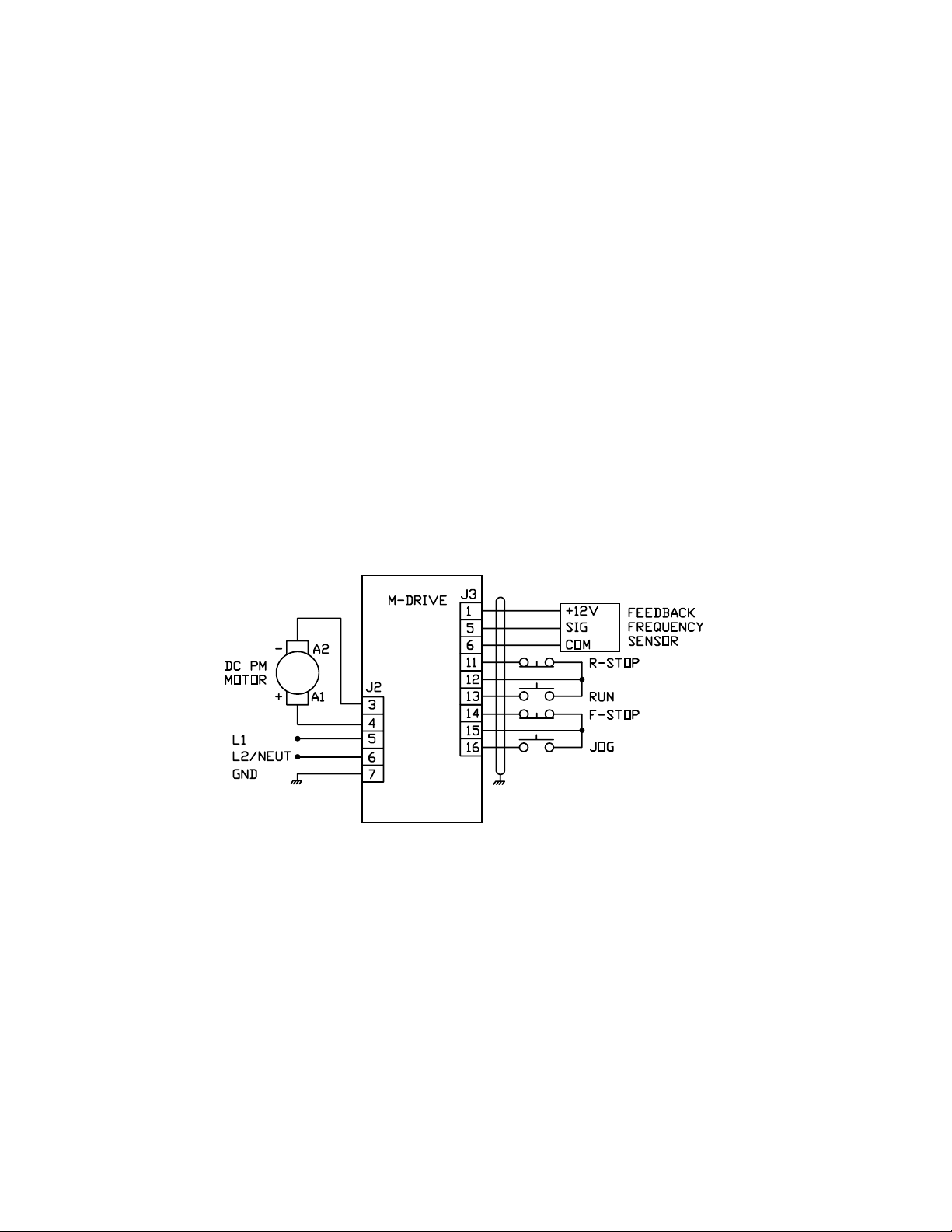
Proper earth grounding of all electronic equipment is required for
successful operation. Connect a low impedance earth ground to
terminal 7 of connector J2.
Separate all logic and signal level wiring (J1, J3 and J4) from all
motor armature and AC power wiring (J2).
Shield all logic and signal wiring (J1, J3 and J4) and terminate to
earth ground at one point only.
REQUIRED WIRING
CC
ONTREX, INC.ONTREX, INC.
C
ONTREX, INC.
ONTREX, INC.ONTREX, INC.
CC
SK1416 Rev 3SK1416 Rev 3
SK1416 Rev 3
SK1416 Rev 3SK1416 Rev 3
Page 1
Page 2

SCALING
After completing the required wiring of the M-Drive, follow the procedure below to scale the M-Drive for Master
format RPM operation. Complete this procedure before scaling the M-Drive for engineering units.
1. While pressing the “CLEAR” and “7” keys on the keypad, apply AC power to the M-Drive
(loads factory default parameters).
2. Enter the pulses-per-revolution of the feedback sensor into CP-31. The keypad sequence for a 60 tooth gear
sensor is “Code Select”, “3”, “1”, “Enter”, “6”, “0”, “Enter”.
3. Enter the maximum system operating RPM into CP-20, CP-22, CP-34 and CP-37. If the feedback sensor is not
directly connected to the motor shaft, enter the maximum feedback sensor shaft RPM.
4. Press the “SETSPEED” key and enter ½ of the RPM entered in Step 3.
5. Press the RUN pushbutton.
6. Verify the motor direction is forward (exchange A1 and A2 if not forward).
7. Press the “TACH” key. Verify an RPM reading appropriate to the motor setpoint speed.
8. Press the R-Stop pushbutton.
The M-Drive is now properly scaled in RPMs. If engineering unit setpoints and/or displays other than RPMs are
desired, refer to Chapter 5 of the “M-Drive User Manual” .
TUNING
If the drive system acts unstable or sluggish in response to setpoint or load changes, it may be necessary to tune the
M-Drive. Follow the procedure below to improve system performance:
1. Set CP-66 (Integral) and CP-67 (Derivative) to zero.
2. Reduce CP-65 (Gain) until the system goes unstable (erratic). Stability can be tested by moving between two
wide spread setpoint values. When instability is reached, increase the CP-65 number slightly until the system
stabilizes (larger values reduce the system gain).
3. Using only Gain, the system setpoint value may never be reached due to system losses. Reduce CP-66 (Integral)
until the system becomes unstable, then increase the Integral number slightly until the system stabilizes and the
desired setpoint value is reached.
4. Derivative (CP-67) is only required if the system is too sluggish after setting the Gain and Integral terms. The
Derivative value, like Gain, should be reduced to the point of instability, then increased slightly until the system
regains stability.
CC
ONTREX, INC.ONTREX, INC.
C
ONTREX, INC.
ONTREX, INC.ONTREX, INC.
CC
SK1416 Rev 3SK1416 Rev 3
SK1416 Rev 3
SK1416 Rev 3SK1416 Rev 3
Page 2
Page 3

FOLLOWER OPERATION
Complete the “Scaling” and “Tuning” procedures for Master mode (Page 2) before proceeding with Follower opera
tion. To enable Follower operation, follow the procedure below:
1. Wiring additions:
2. Enter the pulses-per-revolution of the lead (External Reference) sensor into CP-30 (PPR Ext Ref).
3. Enter the maximum system operating RPM of the lead motor (or sensor shaft if not directly connected to the
motor) into CP-36 (RPM Ref Secondary Max).
4. The M-Drive is now scaled for ratio follower operation. Setpoint and display values are in ratio of follower/lead.
If engineering unit setpoints and/or displays other than ratio are desired, refer to Chapter 5 of the “M-Drive User
Manual”.
5. Enter the desired operating ratio into CP-3 (Follower Setpoint).
TROUBLE-SHOOTING
Master Mode: Motor Will Not Run
Step 1: Check MV-53 (Control State).
a) Should be “32” (Run).
b) If not “32”, check the Run, R-Stop and F-Stop wiring.
Step 2: Check MV-45 (Scaled Reference).
a) Should not be zero.
b) Press “SETSPEED” and enter a midrange value setpoint.
c) Enter a value greater than max motor speed (CP-34) into CP11 (Maximum Limit).
d) Enter a “1” into CP-61 (Scaling Mode Pri) and CP-63 (Display Mode Pri).
Step 3: Check MV-46 (Ramped Reference).
a) Should not be zero.
b) If MV-46 is zero, check MV-54 for a value of 247 or 255.
c) If MV-54 is not 247 or 255, check wiring according to Chapter 3 of the “M-Drive User Manual”.
CC
ONTREX, INC.ONTREX, INC.
C
ONTREX, INC.
ONTREX, INC.ONTREX, INC.
CC
SK1416 Rev 3SK1416 Rev 3
SK1416 Rev 3
SK1416 Rev 3SK1416 Rev 3
Page 3
Page 4

Step 4: Check MV-47 (Output).
a) Should not be “0” or “100”.
b) If “0”, then return to step 1 of “Scaling”.
c) If “100”, check wiring to motor.
Step 5: If armature contactor is used, make sure it is energized.
Master Mode: Motor At Full Speed
Step 1: Press “SETSPEED” and enter midrange setpoint.
Step 2: Check MV-43 (Feedback Frequency).
a) Should not be zero.
b) Check that signal is present at feedback input (J3 Pins 5 and 6).
c) Check the feedback configuration jumpers per Chapter 2 of the “M-Drive User Manual”.
Step 3: Stop the M-Drive.
Step 4: If motor does not stop, check MV-47 (Output).
a) Should be zero.
b) Check MV-53: Should be “64” or “128”.
c) If not, check R-Stop and F-Stop wiring.
Step 5: If motor is still running, suspect false-fired or bad SCR’s.
Follower Mode: Motor Will Not Run
Step 1: Check unit out in Master Mode first.
Step 2: Check MV-54 (Control Mode)
a) Should be less than 128.
b) If not, check wiring to verify that Follower mode has been selected.
Step 3: Check MV-53 (Control State)
a) Should be “32” (Run).
b) If not, check Run, R-Stop and F-Stop wiring.
Step 4: Check MV-41 (External Reference Frequency).
a) Should display the lead sensor frequency.
b) If not, check signal at External Reference Frequency input, and the configuration jumpers per Chapter 2
of the “M-Drive User Manual”.
Step 5: Check MV-45 (Scaled Reference).
a) Should not be zero.
b) If zero, press “SETSPEED” and enter a non-zero ratio setpoint.
c) Check CP-11 (Maximum Limit) and enter a value greater than CP-37 (RPM Fdbk Secondary Max).
CC
ONTREX, INC.ONTREX, INC.
C
ONTREX, INC.
ONTREX, INC.ONTREX, INC.
CC
SK1416 Rev 3SK1416 Rev 3
SK1416 Rev 3
SK1416 Rev 3SK1416 Rev 3
Page 4
 Loading...