

Page 1

CX-1102
STARTUP GUIDE
SK1676 Rev A
Page 2

Page 3

INTRODUCTION
The CX-1102 motion controller is used with various types of motor drives for precision control of unwind/
wind applications. The typical application consists of a web or line coming off of a powered unwind roll,
passing through a dancer loop and being taken up on a powered rewind roll. Both axis must have quadrature
(bidirectional) encoders either on the motor shaft or on the roll shaft. Generally both of the axis will be under
control of the CX-1102. It is possible, however , that one of these rolls will be under external control.
This guide is intended to assist with the start up of elementary unwind/wind systems. More involved
applications should be implemented only after the system is working as herein described. Refer to the CX-
1 102 Technical Reference Manual for a comprehensive and detailed explanation of the CX-1102’s features
and operations.
The CX-1102 start-up procedure consists of:
• Basic Wiring
• Operator Interface Primer
• System Setup Procedure
The following assumptions are made:
• Except for the changes required here, the CX-1102, including its PLC, will be programmed as factory
default.
• The default tuning for the CX-1102 should be stable for most applications and will not be discussed
here.
• Quadrature sensors are required for all applications.
This information is useful (but not essential) to complete setup.
• Dancer Mechanical Design: The Dancer content is the length of web material stored in the dancer
between its empty and full positions. This storage must be at least equal to 0.5 seconds of web travel at
maximum Line Speed. The nominal operating point, or Dancer Setpoint, should position the dancer at
approximately mid-range between empty and full.
The length and angle of the dancer arm should result in a near linear relationship of dancer position vs
dancer content. Avoid high angles of dancer rotation, or severe angles of web entry or web exit paths.
The web tension is determined by the loading on the dancer arm, either by deadweight, or by
pneumatic cylinder. The CX-1102 attempts to maintain dancer position, and does not directly control
web tension.
Page 1
Page 4

• Dancer Electrical Design: The analog electrical signal from the dancer should be stable, repeatable,
noise-free, and linear with respect to dancer movement. It can be a potentiometer, or some non-contact
analog sensor. Sonar or ultrasound detectors on a free loop web may not be acceptable due to
instability or low resolution.
The electrical signal does not necessarily have to traverse the entire 0 to 5 vdc range over the dancer
range of physical motion. It must traverse at least a 1 volt minimum electrical range, and more voltage
swing would improve resolution and accuracy of calculations.
• Axle vs Surface encoders: Axle encoders are simpler to install, and usually have a more rugged
mounting location.
Surface traction-wheel or idler- roll mounted encoders may yield more accurate surface speeds, but are
more cumbersome to mount. Web-breaks, or web slippage can cause undesirable results.
• Use of Traction-Wheel or Idler-Roll encoders: Choose “Fixed Diameter” configuration option, just
as though that axis is a fixed nip-roll design. A Traction-Wheel with a 1-foot circumference is entered
as a 3.82 inch diameter roll. (12 inch/π)
• Roll RPM vs Motor RPM: The CX-1102 never asks how fast the motor can go. RPM always refers
to the speed of the roll axle. Please study the mechanical design of the machine to understand the gear
reduction between motor, encoder and roll axle. Only the top axle RPM, and the Gear Reduction from
encoder to axle are parameter entries in the CX-1102.
• Accel/Decel Rates: Adjust the Accel/Decel rates in the motor drive (amplifier), on each axis, to their
fastest rates (shortest time), to allow the CX-1102 command signals to promptly generate a correct
response from the motor. However, adjust the Accel/Decel rates in the CX-1102 to more gentle ramps
to allow the dancer trim to work smoothly and effectively at startup.
• Safety Stops/Inhibits/Enables: The CX-1102 has Drive Enable open collector outputs, to be used (via
pilot relays if needed) to enable/disable the motor drive. This is important since there are situations
where the CX-1102 is trying to hold an axle in a “live zero”, or “active stopped”, H-Stop state. At
other times the axis is turned off (disabled). While the drive enable function could be part of some
external process control scheme, it is best to let the CX-1102 control the drives as required by the
internal control algorithms. Having said this, also consider SAFETY. The CX-1102 stop commands
are solid state items. Overall system safety would require interlocked, external, pushbuttons, contacts,
etc. to effect a disconnect type of safety stop. CX-1102’s “live zero” may appear to be a stopped
condition, but would NOT be safe to enter the machine for thread-up, jam clearing, etc.
• Web Stretch: Greatest accuracy is obtained with
Non-extensible webs. Some minor (<2%) web
stretch, or shrinkage, is usually acceptable but may affect line speed accuracy. If web stretch is
expected, enter the anticipated stretch value into Stretch % (CP-220) to normalize the dancer trim
effect.
• Unipolar (Non-reversible) Drives: The CX-1102 is typically used with bi-directional (reversible)
drives. It can accommodate unipolar drives (or brake in limited cases), only with appropriate design
considerations. The unipolar drive axis must have sufficient gearbox friction to prevent back-driving,
or overhauling loads. That is, it must prevent being pulled backwards, or pulled forwards faster than it
intended to go, due to web tension. Otherwise, the dancer position cannot be maintained properly.
Page 2
Page 5

—NOTES—
Page 3
Page 6

BASIC WIRING
WARNING
The CX-1102 should only be installed by a qualified electrician.
Hazardous voltages may cause severe injury, death or equipment
damage.
The CX-1102 General Wiring Diagram illustrates the complete power and signal wiring for the CX-1102 control. Not
all of the connections will be required for your application. Refer to the CX-1102 Technical Reference Manual for
complete installation and wiring instructions.
The following instructions describe the basic wiring required for the unwind and wind modes of operation:
Power (J4 pins 1,2,3)
Position the power selector switch on the back of the CX-1102 to configure the power supply for 115 or 230 VAC. Wire
the power as shown in the diagram for 115 or 230 VAC.
WARNING
Applying 230 VAC power with the power selector switch in the
115 position will result in damage to the CX-1102 controller.
Run/Stop Logic (J6 pins 1,2,3,4,6)
In order to put the CX-1102 into “Run”, the F-Stop, Unload and H-Stop inputs must be shorted to common, usually
through a normally closed pushbutton. Short the Run input to common, usually through a normally open momentary
pushbutton. Thereafter, opening any of the Stop inputs will cause the CX-1102 to stop.
Unwind Jog Fwd/Rvs (J7 pins 1,2,3)
Unwind Jog Fwd/Rvs is a maintained input. When it is closed, it sends a Control Output signal to the drive at the
selected Jog Setpoint. As a maintained input, Unwind Jog Fwd/Rvs is only active when the operator device is closed.
Wind Jog Fwd/Rvs (J7 pins 4,5,3)
Wind Jog Fwd/Rvs is a maintained input. When it is closed, it sends a Control Output signal to the drive at the selected
Jog Setpoint. As a maintained input, Wind Jog Fwd/Rvs is only active when the operator device is closed.
Unwind Control Output (J3 pins 1,2)
The Unwind Control Output is a two wire connection between the CX-1102 and the Unwind motor drive. Insure that the
isolated common (J3 pin 2) is not used elsewhere.
Wind Control Output (J8 pins 1,2)
The Wind Control Output is a two wire connection between the CX-1102 and the Wind motor drive. Insure that the
isolated common (J8 pin 2) is not used elsewhere.
Unwind Enable and Wind Enable (J2 pins 1,2,3,10)
When these digital outputs are wired to the appropriate control input of the subject drive, it allows the CX-1102 to enable
and disable the drive as required. A low voltage pilot relay is usually required.
Frequency Inputs (J5 pins 1 thru 11)
The CX-1102 requires quadrature encoders for the unwind/wind frequency inputs. Refer to the CX-1102 Technical
Reference Manual for detailed diagrams illustrating the connections for the frequency sensors.
Setup (J6 pin 10,8)
The Setup input is a maintained input. It is used only during the system setup procedure to put the CX-1102 into “Setup
State”.
KeyLk (J6 pin 9,8)
The KeyLk input is a momentary input. It is used temporarily during the system setup procedure of the CX-1102.
Page 4
Page 7
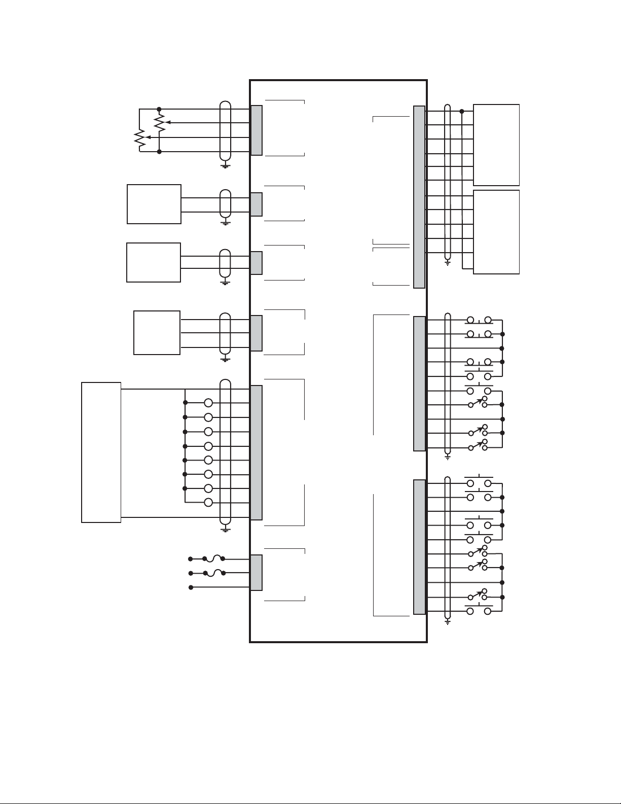
CX-1102 General Wiring Diagram
RS485
Serial
Communications
Interface
+
EXTERNAL
DC
POWER
SUPPLY
(50V MAX)
-
Signal Input
Drive Common
Unwind Motor Drive
Signal Input
Drive Common
Wind Motor Drive
TD/RD +
TD/RD -
Com
Unwind Enable
Wind Enable
Unwind Error
Wind Error
Wind Roll Full
Dancer
Web Break
Spare
FUSES
1 A
250 V
230 VAC
115 VAC
L1
L1
L2
NEUT
GND/PE
GND/PE
Dancer
Line Speed
JA
+5VDC
1
Dncr
2
LnSpd
3
Com
4
Analog Card
J3
SigU
1
ComU
2
Output
Control
To UWnd Drv
J8
SigW
1
ComW
2
Output
Control
To Wnd Drv
J1
TD/RD +
1
TD/RD -
2
Com
3
RS485
Serial Comm
J2
+V_DO
1
R
R
R
R
R
R
R
R
UwdEn
2
WdEn
3
UErr
4
WErr
5
WRlFl
6
Dncr
7
WbBrk
8
Spare
9
Com
10
Digital Outputs
J4
L1
1
L2/NEUT
2
GND/PE
3
INPUT
AC POWER
J5
* +5VDC
UnWind Wind
A
-
A
B
Encode Inputs
-
B
Com
A
-
A
B
-
B
Reserved
Com
RI_1
RI_2
J6
F-Stp
UnLd
Com
H-Stp
Load
Run
Spare
Com
KeyLk
Digital Inputs
Setup
J7
UJogF
UJogR
Com
WJogF
WJogR
UuWrp
WuWrp
Com
LSRvs
WbRst
1
2
3
4
5
6
7
8
9
10
11
NC
12
NC
13
1
2
3
4
5
6
7
8
9
10
1
2
3
4
5
6
7
8
9
10
+5V PWR
A
-
A
B
-
B
Common
A
-
A
B
-
B
Common
+5V PWR
Unwind
Quadrature
Sensor
Wind
Quadrature
Sensor
F-Stop
UnLoad
H-Stop
Load
Run
Spare
Keypad Lockout
Setup
Unwind Jog Forward
Unwind Jog Reverse
Wind Jog Forward
Wind Jog Reverse
Unwind Under Wrap
Wind Under Wrap
Line Speed Reverse
Web Reset
CX-1102
*
Power for frequency input sensors may be supplied by J5, pin 1.
Total current should not exceed 150 mA .
Page 5
Page 8

OPERATOR INTERFACE PRIMER
The remainder of the CX-1102 setup procedure involves setting control parameter values through the operator interface,
and then verifying system behavior using monitor parameters. The basic procedure for changing a control parameter is
first to locate the relevant parameter using the Menu, Page Up/Down and Parameter Up/Down keys, and then to modify
the parameter value using the Numeric or Scroll Up/Down keys.
The sequence for locating a control or monitor parameter using the menu driven interface is:
• Press the Menu key repeatedly until the Main Menu is displayed.
• Press the Parameter Up/Down keys to select the sub menu.
• Press the Enter key.
• Press the Parameter Up/Down keys to select the parameter category.
• Press the Enter key.
• Press the Page Up/Down keys, if necessary, to select the page.
• Press the Parameter Up/Down keys to select the parameter.
An alternative method for locating a parameter is through the code select procedure:
• Press the Code key to activate the code select line.
• Enter the numeric parameter code.
• Press the Enter key.
• The selected parameter is now displayed on the Status screen.
For each control parameter (CP) and monitor parameter (MP) required, the menu path will be shown as:
Go to MAIN MENU\DEVICE SETUP\SYSTEM SETUP\PAGE 1.
Enter App Select {CP-202} = 0 = Direct Mode.
The menu selections are separated by back slashes, “\”. The parameter code is
shown in the brackets,{}.
NOTE: The Help key accesses the Help screen and gives you a brief description of the parameter or subject that is
highlighted (active) on the screen. Press the Help key again to return to the previous screen.
Page 6
Page 9

LCD
r
)
S
S
K
P
U
K
t
s
Screen
Display
Menu
Key
CX-1102 Operator Interface
ONTREX
C
CX - 1102
MAIN MENU
SETUP
SCALING
SETPOINTS & RAMPS
TUNING
ALARMS & LIMITS
BLOCKS
PLC
SYSTEM MONITOR
DEVICE TEST
Alm
MENU
Paramete
Up/Down
Keys
(Par Up)
(Par Dwn
Menu
Code
Key
CODE
tatus
creen
ey
age
p/Down
eys
Numeric
Keys
STATUS
7
4
1
-
89
5
23
0
HELP
Help
Screen
Key
6
CLEAR
.
ENTER
Incremen
Scroll Up/
Down Key
Clear
Key
Enter
Key
Page 7
Page 10

SYSTEM SETUP PROCEDURE
This procedure is a series of steps designed to verify the motor/drive/encoder wiring and polarity, calibrate the dancer
and setup some of the basic parameters necessary for proper operation of the CX-1102.
Before you begin this procedure, the motor and drive must be wired and configured in accordance with the manufacturer’s
instructions. Refer to your drive manual to assist you in making the following drive adjustments:
• Set the acceleration and deceleration times to their fastest settings.
• Set the IR compensation to its minimum setting.
• Set the Integral compensation to its minimum setting.
The CX-1102 must be configured and installed in accordance with the installation procedures indicated in the Installa-
tion section of the CX-1102 Technical Reference Manual and the CX-1102, including its PLC, will be programmed as
factory default.
NOTE: The Wind Under Wrap input MUST be shorted to common if the wind axle will have web material fed onto
the roll from the bottom rather than the top of the roll. The Unwind Under Wrap input MUST be shorted to
common if the unwind axle will have web material fed off of the roll from the bottom rather than the top of
the roll.
NOTE: The Menu and Status keys will be disabled during the setup procedure. This is done in order to simplify the
automatically displayed screen sequence used while performing the setup procedure.
NOTE: Unipolar drives should not be used unless there is a large gear reduction between the motor and the roll,
because the unipolar drive can not provide reverse torque to hold the roll in position.
NOTE: The F-stop, Unload and H-Stop inputs are monitored during "Setup State". If any of these inputs are
opened during a test the CX-1102 will immediately zero the Control Outputs and display "Failure" for the
test in progress.
Setup consists of the following:
• Application Configuration
• Axis Configuration
• Wind Roll Setup
• Unwind Roll Setup
• Signal Polarity Test
• Dancer Calibration
• Wind Direction Test
• Unwind Direction Test
DANGER
Motion will occur in the calibration procedure.
It is possible that sudden/violent motion could
result and cause damage or personal injury.
Make sure that the motor is secured in place.
Take all possible precautions to ensure your
safety.
Page 8
Page 11

DANGER
Hazardous voltages.
Can cause severe
injury, death or
damage
the equipment.
Make adjustments
with caution.
Page 9
Page 12

Step 1 - Application Configuration - Parameter Entry
Close the "Setup" input. The CX-1102 will change to "Setup State" and will automatically display
System Setup Application\Page 1. Setup State {MP-59} will equal 0.
Configure the CP’s on this screen as required.
System State {MP-50}
Setup State {MP-59}
App Select {CP-202}
UnitPrs Sel {CP-208}
Time Base {CP-209}
FixedDiaSel {CP-207}
UwndDiaPrst {CP-364}
WindDiaPrst {CP-365}
NOTE: The Help key accesses the Help screen and gives you a brief description of the parameter or
subject that is highlighted (active) on the screen. Press the Help key again to return to the previous screen.
Press the "Page Down" key to proceed to the next step.
Step 2 - Axis Configuration - Parameter Entry
The CX-1102 will display System Setup Axis Configuration\Page 2.
Setup State {MP-59} will equal 1 (not displayed on this screen).
Configure the CP’s on this screen as required.
WindCO Mode {CP-285}
WindCO MaxVolts {CP-286}
Wind PPR {CP-266}
WindGearRdcn {CP-265}
Wind MaxRPM {CP-329}
UwndCO Mode {CP-280}
UwndCO MaxVolts {CP-281}
Unwind PPR {CP-261}
UwndGearRdcn {CP-260}
Uwnd MaxRPM {CP-329}
NOTE: The Help key accesses the Help screen and gives you a brief description of the parameter or
subject that is highlighted (active) on the screen. Press the Help key again to return to the previous screen.
Press the "Page Down" key to proceed to the next step.
Page 10
Page 13

Step 3 - Wind Roll Setup - Parameter Entry
The CX-1102 will display System Setup Wind Roll\Page 3.
Setup State {MP-59} will equal 2.
Configure the CP’s on this screen as required.
Setup State {MP-59}
FixedDiaSel {CP-207}
LoadDiaCalEn {CP-361}
WindMinDia {CP-352}
WindMaxDia {CP-353}
WindDiaPrst {CP-365}
WindCtntPrst {CP-367}
WindCtntRO {CP-369}
WindEstDia {MP-17}
WindEstCtnt {MP-16}
NOTE: The Help key accesses the Help screen and gives you a brief description of the parameter or
subject that is highlighted (active) on the screen. Press the Help key again to return to the previous screen.
Press the "Page Down" key to proceed to the next step.
Step 4 - Unwind Roll Setup - Parameter Entry
The CX-1102 will display System Setup Unwind Roll\Page 4.
Setup State {MP-59} will equal 3.
Configure the CP’s on this screen as required.
Setup State {MP-59}
FixedDiaSel {CP-207}
LoadDiaCalEn {CP-361}
UwndMinDia {CP-350}
UwndMaxDia {CP-351}
UwndDiaPrst {CP-364}
UwndCtntPrst {CP-366}
UwndCtntRO {CP-368}
UwndEstDia {MP-07}
UwndEstCtnt {MP-06}
NOTE: The Help key accesses the Help screen and gives you a brief description of the parameter or
subject that is highlighted (active) on the screen. Press the Help key again to return to the previous screen.
Press the "Page Down" key to proceed to the next step.
Page 11
Page 14

Step 5 - Signal Polarity Test
The CX-1102 will display System Setup Signal Polarity\Page 5. Setup State {MP-59} will equal 4.
Setup State {MP-59}
WindCO Volts {MP-37}
WindCOPolarity {CP-287}
WindEncRPM {MP-12}
WindEncPty {CP-269}
UwndCO Volts {MP-27}
UwndCOPolarity {CP-282}
UwndEncRPM {MP-02}
UwndEncPty {CP-264}
SigPolarity {MP-71}
NOTE: The Help key accesses the Help screen and gives you a brief description of the parameter or
subject that is highlighted (active) on the screen. Press the Help key again to return to the previous screen.
This test aligns the Control Output polarity and the Encoder polarity, so a positive Control Output command causes
positive Encoder feedback.
If the wind and/or unwind axis is under CX-1102 control:
NOTE: This step will make use of "Direct" mode and ramps.
NOTE: The Keypad will be disabled while this test is moving the wind/unwind axis.
WARNING
Prepare the machine for motion.
Alert everyone present.
The CX-1102 will flash "KeyLk" in the bottom center of the display.
Wind Polarity Test:
1) Momentarily close the KeyLk input to initiate the test.
2) The CX-1102 will test the wind axis.
For Bipolar and Unipolar Reversing Drives: The CX-1102 will ramp the Control Output command
positive, and back to zero, then negative, and back to zero.
For Unipolar Drives: The CX-1102 will ramp the Control Output command positive, and back to
zero. If no feedback occurs, it will negate WindCOPolarity {CP-287}, then ramp the Control Output
command positive, and back to zero.
Page 12
Page 15

Fail test:
The CX-1102 will flash "Wind Failure" then "Pg Up" in the bottom center of the display.
Check the following:
a. Control Output Unwind/Wind wiring to the drive
b. encoder input wiring
c. drive armature and power wiring
d. is the drive enabled
e. is this a Unipolar Reverse setup - check the PLC program and verify the correct
connection to the drives reversing input.
Press the "Page Up" key to restart this step (Wind Polarity Test).
Pass test:
The CX-1102 will flash "Wind PASS" then "KeyLk" in the bottom center of the display.
Setup State {MP-59} will equal 5.
The CX-1102 will change the WindEncPty {CP-269} to match the control output signal based on the
recorded information. For unipolar drives, WindCOPolarity {CP-287} may also have been changed
based on the recorded information.
If the wind axis is NOT under CX-1102 control:
1) Rotate the wind roll in the forward direction, then in the reverse direction.
2) Observe the value in WindEncRPM {MP-12} for a sign change. If the sign does not change then check the
encoder input wiring.
Pass test:
The CX-1102 will flash "Wind PASS" then "KeyLk" in the bottom center of the display.
Setup State {MP-59} will equal 5.
Unwind Polarity Test:
1) Momentarily close the KeyLk input to initiate the test.
2) The CX-1102 will test the unwind axis.
For Bipolar and Unipolar Reversing Drives: The CX-1102 will ramp the Control Output command
positive, and back to zero, then negative, and back to zero.
For Unipolar Drives: The CX-1102 will ramp the Control Output command positive, and back to
zero. If no feedback occurs, it will negate UwndCOPolarity {CP-282}, then ramp the Control Output
command positive, and back to zero.
Fail test:
The CX-1102 will flash "Uwnd Failure" then "Pg Up" in the bottom center of the display.
Check the following:
a. Control Output Unwind wiring to the drive
b. encoder input wiring
c. drive armature and power wiring
d. is the drive enabled
e. is this a Unipolar Reverse setup - check the PLC program and verify the correct
connection to the drives reversing input.
Press the "Page Up" key to restart this step (Wind Polarity Test).
Pass test:
The CX-1102 will flash "Unwind PASS" then "Pg Down" in the bottom center of the display.
Setup State {MP-59} will equal 6.
Page 13
Page 16

The CX-1102 will change the UwndEncPty {CP-264} to match the control output signal based on
the recorded information. For unipolar drives, UwndCOPolarity {CP-282} may also have been
changed based on the recorded information.
If the unwind axis is NOT under CX-1102 control or is Unipolar Brake:
1) Rotate the unwind roll in the forward direction, then in the reverse direction.
2) Observe the value in UwndEncRPM {MP-02} for a sign change. If the sign does not change then check the
encoder input wiring.
Pass test:
The CX-1102 will flash "Uwnd PASS" then "Pg Down" in the bottom center of the display.
Setup State {MP-59} will equal 6.
Press the “Page Down” key to proceed to the next step.
Page 14
Page 17

Step 6 - Dancer Calibration
The CX-1102 will display automatically System Setup Dancer\Page 6. Setup State {MP-59} will equal 6.
Setup State {MP-59}
DncrFullVolts {CP-271}
DncrEmptyVlts {CP-273}
DncrCtntFull {CP-272}
Dancer SP {CP-250}
DancerCtnt {MP-82}
Dancer State {MP-58}
Dancer Volts {MP-81}
NOTE: The Help key accesses the Help screen and gives you a brief description of the parameter or
subject that is highlighted (active) on the screen. Press the Help key again to return to the previous screen.
WARNING
For safety, place the CX-1102 into F-Stop
during the dancer calibration.
The CX-1102 will flash "Dncr to Full" then "KeyLk" in the bottom center of the display.
Move the dancer to the "FULL" position, hold it there. Momentarily close the KeyLk input, the CX-1102 will
store the value from Dancer Volts {MP-81} into DncrFullVolts {CP-271}. Setup State {MP-59} will incre
ment to 7.
The CX-1102 will flash "Dncr toEmpty" then "KeyLk" in the bottom center of the display.
Move the dancer to the "EMPTY" position, hold it there. Momentarily close the KeyLk input, the CX-1102 will
store the value from Dancer Volts {MP-81} into DncrEmptyVlts {CP-273}.
Fail test:
If the voltage-swing DOES NOT exceed the required 1 volt difference, the CX-1102 will flash
"Error <1v". The CX-1102 will NOT proceed to the next step until this has been corrected.
Press the "Page Up" key to restart this step (Dancer Calibration).
Pass test:
The CX-1102 will flash "Dancer PASS" then "Pg Down" in the bottom center of the display.
Setup State {MP-59} will increment to 8.
NOTE: At this time thread up the machine, measure the web material that is stored in the dancer between
its full and empty positions and enter it into DncrCtntFull {CP-272}. Also enter your Dancer SP {CP250}. The Jog inputs (jog is open loop at this time) are available to assist in threading the machine prior to
running the Direction tests. Since the direction tests have not been performed yet, the Jog movment may
not match the Jog input labels.
Press the "Page Down" key to proceed to the next step.
Page 15
Page 18

Step 7 - Wind Direction Test
The CX-1102 will display automatically System Setup Wind Direction\Page 7.
Setup State {MP-59} will equal 8.
Setup State {MP-59}
Wind State {MP-48}
WindCO Volts {MP-37}
WindRollRPM {MP-13}
DancerCtnt {MP-82}
WindCOPolarity {CP-282}
WindEncPlrty {CP-264}
Wrap Polarity {MP-70}
Sig Polarity {MP-71}
Wind Dirn {MP-61}
NOTE: The Help key accesses the Help screen and gives you a brief description of the parameter or
subject that is highlighted (active) on the screen. Press the Help key again to return to the previous screen.
REMINDER: The Wind Under Wrap input MUST be shorted to common if the wind axle will have web
material fed onto the roll from the bottom rather than the top of the roll. This needs to be done so the
proper polarity can be determined in the following step.
If the wind axis is under CX-1102 control:
This test sets the Control Output and Encoder polarities so a positive command equals forward direction.
NOTE: The Keypad will be disabled while this test is moving the wind axis.
The CX-1102 will now display “KeyLk” (flashing) in the lower center of the display.
NOTE: The web must be threaded into the machine (and dancer), and the dancer in the (relaxed) full
position with the web material tight against the dancer.
WARNING
Prepare the machine for motion.
Alert everyone present.
1) Momentarily close the KeyLk input. The CX-1102 will send a positive command to the Wind axis, for
forward direction. The CX-1102 will montior the Dancer content for movement away from the Full position.
If the Dancer does not move after X number of rotations of the Wind roll, the Wind axis is stopped.
If WindCO Mode {CP-285} is set to Unipolar, this test Fails.
If WindCO Mode {CP-285} is set to Bipolar or Unipolar Reversing, WindCOPolarity {CP-287} and
WindEncPlrty {CP-269} are changed, and a positive command is issued to the Wind axis again
for forward rotation (maximum of 2X number of rotations). The CX-1102 will montior the Dancer
content for movement away from the Full position.
Page 16
Page 19

If the dancer moves from Full to approximately 3/4 of Full, the Wind roll is stopped, the Dancer will
be held in position, and the test Passes.
Fail test:
Check the following:
a. is web threaded into machine
b. drive armature and power wiring
c. is the drive enabled
d. gear reduction is correct
Press the "Page Up" key to restart this step (Wind Direction Test).
Pass test:
The CX-1102 will flash "Wind PASS" then "Pg Down" in the bottom center of the display.
Setup State {MP-59} will equal 9.
Proceed to End of Wind Direction Test.
If the wind axis is NOT under CX-1102 control, if App Select {CP-202} is a 3 (DT Unwind only):
1) Momentarily close the KeyLk input. The CX-1102 will montior the Wind feedback and the Dancer content
for movement away from the Full position to approximately 3/4 of Full.
2) Rotate the Wind roll in the forward direction.
3) When the dancer moves, the CX-1102 will change the WindEncPlrty {CP-269} value so WindRollRPM
{MP-13} is a positive (no ‘-‘ sign) signal for forward rotation of the Wind roll, the dancer should be held in
position, and the test Passes.
Fail test:
Check the following:
a. is web threaded into machine
b. drive armature and power wiring
c. is the drive enabled
Press the "Page Up" key to restart this step (Wind Direction Test).
Pass test:
The CX-1102 will flash "Wind PASS" then "Pg Down" in the bottom center of the display.
Setup State {MP-59} will equal 9.
End of Wind Direction Test
Press the "Page Down" key to proceed to the next step.
Page 17
Page 20

Step 8 - Unwind Direction Test
The CX-1102 will display automatically System Setup Unwind Direction\Page 8.
Setup State {MP-59} will equal 9.
Setup State {MP-59}
Uwnd State {MP-48}
UwndCO Volts {MP-27}
UwndRollRPM {MP-03}
DancerCtnt {MP-82}
UwndCOPolarity {CP-282}
UwndEncPlrty {CP-264}
Wrap Polarity {MP-70}
Sig Polarity {MP-71}
Uwnd Dirn {MP-60}
NOTE: The Help key accesses the Help screen and gives you a brief description of the parameter or
subject that is highlighted (active) on the screen. Press the Help key again to return to the previous screen.
REMINDER: The Unwind Under Wrap input MUST be shorted to common if the unwind axle will have
web material fed off of the roll from the bottom rather than the top of the roll. This needs to be done so the
proper polarity can be determined in the following step.
If the unwind axis is under CX-1102 control:
This test sets the Control Output and Encoder polarities so a positive command equals forward direction.
NOTE: The Keypad will be disabled while this test is moving the unwind axis.
The CX-1102 will now display "KeyLk" (flashing) in the lower center of the display.
WARNING
Prepare the machine for motion.
Alert everyone present.
1) Momentarily close the KeyLk input.
If UwndCO Mode {CP-280} is set to Unipolar Brake, the Unwind roll will be put into F-Stop with a zero volts
command. The CX-1102 will wait for the Dancer content to reach the Full position while monitoring the
Unwind feedback signal.
If UwndCO Mode {CP-280} is set to Unipolar, Bipolar or Unipolar Reversing, the CX-1102 will send a
positive command to the Unwind axis, for forward direction. The CX-1102 will montior the Dancer content for
movement toward the Full position.
If the Dancer moves the wrong direction or does not move after X number of rotations of the Unwind roll, the
Unwind axis is stopped.
Page 18
Page 21

If UwndCO Mode {CP-280} is set to Unipolar, this test Fails.
If UwndCO Mode {CP-280} is set to Bipolar or Unipolar Reversing, UwndCOPolarity {CP-282}
and UwndEncPlrty {CP-264} are changed, and a positive command is issued to the Unwind axis
again for forward rotation (maximum of 2X number of rotations). The CX-1102 will montior the
Dancer content for movement toward the Full position.
If the Dancer moves to its Full position, both rolls are stopped, and the test Passes.
Fail test:
Check the following:
a. is web threaded into machine
b. drive armature and power wiring
c. is the drive enabled
d. gear reduction is correct
Press the "Page Up" key to restart this step (Unwind Direction Test).
Pass test:
The CX-1102 will flash "Uwnd PASS" then "Setup Done" in the bottom center of the display.
Setup State {MP-59} will equal 10.
Proceed to End of Unwind Direction Test.
If the unwind axis is NOT under CX-1102 control, if App Select {CP-202} is a 4 (DT Wind only):
1) Momentarily close the KeyLk input. The CX-1102 will montior the Unwind feedback and the Dancer
content for movement from approximately 3/4 of Full to Full.
2) Rotate the Unwind roll in the forward direction.
3) When the dancer moves, the CX-1102 will change the UwndEncPlrty {CP-264} value so UwndRollRPM
{MP-03} is a positive (no ‘-‘ sign) signal for forward rotation of the Unwind roll and the test Passes.
Fail test:
Check the following:
a. is web threaded into machine
b. drive armature and power wiring
c. is the drive enabled
Press the "Page Up" key to restart this step (Unwind Direction Test).
Pass test:
The CX-1102 will flash "Uwnd PASS" then "Setup Done" in the bottom center of the display.
Setup State {MP-59} will equal 10.
End of Unwind Direction Test
Open the "Setup" input, the CX-1102 control is in F-Stop and will automatically display the "Main Menu" screen.
Remove any temporary terminal wiring.
After completing Setup proceed to the CX-1102 Technical Reference Manual: System Setup/Control Parameters, Scal-
ing.
Page 19
Page 22

—NOTES—
Page 20
Page 23

—NOTES—
Page 21
Page 24

Page 22
CONTREX, INC.
8900 Zachary Lane North
Maple Grove, MN 55369 USA
Phone:763.424.7800
Fax: 763.424.8734
www.contrexinc.com
info@contrexinc.com
 Loading...