

Page 1

424-M-V1.5
BATCH CONTROLLER
MODEL 424
22 Jun 2018
Page 2

424-M-V1.5
Page 3

424-M-V1.5
Contents
1. INTRODUCTION 1
1.1 MODEL NUMBER DESIGNATION 3
2. SPECIFICATION 4
3. OPERATION 6
3.1 FRONT PANEL OPERATION 7
3.2 BATCH OPERATIONS 10
3.2.1 Control Relay Outputs 12
3.2.2 Signal Timeout 13
3.2.3 End of Batch 14
3.2.4 Auto Restart 15
3.2.5 Automatic Overrun Compensation 16
3.3 CALCULATION OF RATE AND TOTAL 17
3.3.1 Frequency Input 17
3.3.2 Filtering 18
3.4 TOTAL CONVERSION 20
3.5 THE OUTPUT PULSE AND FLOW ALARM 21
4. COMMS & OPTIONS 23
4.1 THE RS232/485 INTERFACE 23
4.1.1 Hardware 23
4.1.2 RS232 24
4.1.3 Multipoint Communication 25
4.1.4 Real Time Clock 26
Page 4

424-M-V1.5
4.2 SOFTWARE PROTOCOL 27
4.2.1 Echoing Commands 27
4.2.2 Response Times 27
4.3 COMMANDS AND RESPONSES 28
4.4 PRINTER COMMUNICATIONS 31
4.4.1 Hardware Interconnection 31
4.4.2 Operation 33
4.4.3 Information Printed 33
4.5 THE 4-20mA OUTPUT OPTION 36
4.5.1 Load Specification 37
4.5.2 Calculation 37
5. CALIBRATION 39
5.1 PROGRAMMING THE SETUP PARAMETERS 41
5.2 ENTERING THE BATCH PARAMETERS 43
5.3 PROGRAMMING OPTIONS 45
5.4 TEST MENU 48
6. INPUT CIRCUITS 49
6.1 INPUT CIRCUIT FOR THE MODEL 424 49
6.2 FREQUENCY INPUT CONNECTION 50
6.3 REMOTE SWITCHES 52
7. INSTALLATION & MAINTENANCE 53
7.1 GENERAL 53
7.2 WIRING DESIGNATIONS FOR THE 424 55
Page 5

424-M-V1.5
7.3 MAINTENANCE 56
8. TROUBLE SHOOTING 57
8.1 ERROR CODES 59
Index 60
Page 6

424-M-V1.5
Page 7

424-M-V1.5
Safety Notice
The information in this safety notice is for the prevention of injury to personnel
and damage to the instrument.
Use only in accordance with the instructions provided within this manual.
The manufacturer assumes no liability for injury or damage caused by misuse of
the instrument or modifications made to the instrument.
Qualified Personnel & Maintenance
The instrument must be installed, operated and serviced by persons who have
been properly trained and authorised. Personnel must read and understand this
manual prior to installation and operation of the instrument. Refer to section 7
for further information regarding permitted maintenance operations.
Static Hazard
The user should observe accepted safety practices for handling electronic
devices, especially during servicing.
Voltage Hazard
Before connecting power to the instrument, ensure that the supply voltage for
the AC or DC input is suitable. The AC voltage rating is as stated on the
instrument rating plate. Personnel should take all due care to avoid electric
shock. For safe operation it is essential to connect a mains safety earth to the
A.C. Power inlet. Do not operate at altitudes above 2000m.
Welding Hazard
Do not perform electric welding in close proximity to the instrument or its
interconnecting cables. If welding in these areas must be performed, disconnect
all cables from the instrument. Failure to do so may result in damage to the unit.
Moisture Hazard
To avoid electrical faults and corrosion of the instrument, do not allow moisture
to remain in contact with the instrument. Operate only in a clean, dry and
pollutant-free environment.
Disconnection Device
When powered from a mains supply this unit requires the provision of a suitable
mains isolation device, capable of interrupting both poles of the supply and
meeting your local wiring regulations, to be accessible near to the installed
instrument.
Page 8

424-M-V1.5
FCC Notice
This equipment has been tested and found to comply with the limits for a
Class A digital device, pursuant to Part 15 of the FCC Rules. These limits are
designed to provide reasonable protection against harmful interference
when the equipment is operated in a commercial environment. This
equipment generates, uses, and can radiate radio frequency energy and, if
not installed and used in accordance with the instruction manual, might
cause harmful interference to radio communications. Operation of this
equipment in a residential area is likely to cause harmful interference, in
which case the user will be required to correct the interference at his own
expense.
Properly shielded and grounded cables and connectors must be used in order
to meet FCC emission limits. Contrec Ltd. is not responsible for any radio or
television interference caused by using other than recommended cables and
connectors or by unauthorized changes or modifications to this equipment.
Unauthorized changes or modifications could void the user's authority to
operate the equipment.
This device complies with Part 15 of the FCC Rules. Operation is subject to the
following two conditions: (1) this device might not cause harmful
interference, and (2) this device must accept any interference received,
including interference that might cause undesired operation.
Page 9

424-M-V1.5
Introduction 1
1. INTRODUCTION
The model 424 Batch Controller accepts pulse or frequency flow signals
and automatically controls the batching of fluids via a one or two stage
control valve.
The instruments are extremely flexible and easy to operate, with a four key
front panel operation that enables the batch quantity to be set, and batches
to be started or stopped.
This manual covers both the Model 424.0 and 424.1. While both versions
have identical software and outputs, the Model 424.1 includes a 4-20mA
output circuit.
Model 424 Accepts most frequency and pulse signals,
including mV outputs from turbine flowmeters,
and 2 wire proximity switch outputs. It also
enables all four front panel switches to be
remotely connected via the rear terminal strip.
The Model 424 has a scaled pulse output for driving
remote counters, together with a flow alarm output.
The instrument is fully programmable, with all calculation constants set via the
front panel switches and stored permanently in non-volatile memory.
This instrument is intended for fixed installation only, e.g. within a panel or
cabinet, and is not intended for desktop use.
Page 10

424-M-V1.5
2 Introduction
This instrument conforms to the EMC-Directive of the Council of
European Communities 2014/30/EU, the LVD directive 2014/35/EU and
the following standards:
• EN61326:2013 Electrical equipment for measurement, control and
laboratory use – EMC requirements:
Residential, Commercial & Light Industry Environment & Industrial
Environment.
• EN61010:2010 Safety requirements for electrical equipment for
measurement, control, and laboratory use.
In order to comply with these standards, the wiring instructions in Section 7.1
must be followed.
Page 11

424-M-V1.5
Introduction 3
1.1 MODEL NUMBER DESIGNATION
The model number of an instrument describes which input and output options
are installed.
Model 424 . 1 0 U C
C for Conformal Coating
The model and option of the instrument can be displayed in the Test Menu
(sec 5.4).
Options
0 for no option
1 for 4-20mA Output
Power
U for universal mains supply
D for DC power only
Mounting
1 for Panel Mounting
2 for Field Mounting (contact factory)
3 for Explosion proof
Page 12

424-M-V1.5
4 Specification
2. SPECIFICATION
General
Display: 6 digit LCD. 0.7" (17.8mm) high digits.
Display Update Rate: 0.25 seconds.
Transducer Supply: 8-24VDC software adjustable, 0.2, 0.5, 1V
increments.
70mA max @ 24V, 120mA max @ 12V.
Power Requirements: 13.5 to 28.5 volts DC, 10W.
AC Mains: 100-240 V AC (+/-10%) 50-60 Hz (+/-10%), 10W
Operating Temperature: 0 to 55°C standard.
-20°C to 60°C with conformal coating option.
Dimensions: 5.7" (144mm) wide x 2.8" (72mm) high x
7.0" (178mm) deep.
Cutout: 5.5" (139mm) wide x 2.6" (67mm) high.
Installation: This instruments is intended for fixed
installation only, e.g. within a panel or
cabinet, and is not intended for desktop
use.
Frequency Input
Frequency Range: Minimum: 0.25Hz on Rate.
0Hz on Total.
Maximum: 10KHz - Pulse, 2.5KHz Coil and
NPS
Input Circuits: Will accept most sine logic and proximity
switch inputs (see section 6.1).
Scaling Range: 0.1000 to 50,000.
Relay Outputs
Maximum Switching Power: 1250VA.
Maximum Switching Voltage: 250VAC, 30VDC.
Maximum Switching Current: 5 Amps.
Page 13

424-M-V1.5
Specification 5
4-20mA Output
Resolution: 12 bits.
Accuracy: Better than 0.1%.
Maximum Load: 390 ohms internally powered from +15V
(Terminal 3, +15V and 6, 0V )
950 ohms from 24Vdc or if internal I (-) = -15V
(Terminal 3, +15V and 7, -15V )
See page 38.
Isolation: Output is isolated.
Pulse Output
Pulse Width: 1,10,100mSec (negative going pulse).
Maximum Duty Cycle: 499,49,4.9 pulses per second - according to
pulse width setting.
Output: An open collector transistor will sink
100mA.
Scaling: The pulse output is scaled and outputs one
pulse each time the accumulated total
increments to its maximum limit.
E.g. With a pulse width setting of 10mSec the unit can output a maximum of 50
pulses per second. The scaling of t.dpt must be set so that the least significant
digit of the accumulated total does not exceed 50 increments per second (Hz).
Page 14
424-M-V1.5
6 Operation
3. OPERATION
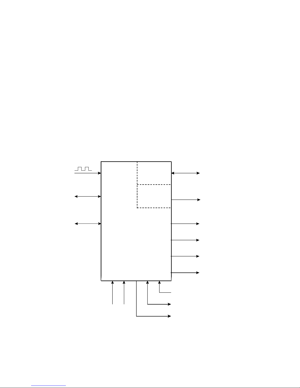
The model 424 Batch Controllers use a low power CMOS microprocessor
to perform all control functions and calculations.
The instruments are fully programmable with all operating parameters and
calculation constants user programmable. (See Section 5 entitled
'Calibration' for information on programming). All parameters and constants
are stored in a non-volatile memory which retains data without battery
backup for a minimum of 10 years.
A block diagram of the instrument is shown below.
Pulse Input
Signal
Common
RS232/485
Comms
DC Input Power
DC Power Ground
DC Power Output to Sensors
Model 424
RS232/485
Relays
End Of Batch (EOB) /
Pump Control (PC)
110-220V
AC Mains
Control
Relay Outputs (2)
Pulse
Output
Flow Alarm
4-20mA
Output
4-20mA
Output
Remote
Switches
Page 15

424-M-V1.5
Operation 7
3.1 FRONT PANEL OPERATION
The four key operation of the Batch Controller is straightforward.
SETTING THE BATCH QUANTITY
The Batch quantity is programmed as follows:
Switch Action Display Comments
Press BATCH SET Batch 'Batch' is displayed for one second
followed by the batch quantity last
entered. The Batch Set LED lights.
'1' 2345 The most significant digit flashes
indicating that it can be changed.
Press '2' 2345 Pressing the DISPLAY key will
increment the digit. (The up arrow on the
Display key indicates to increment digit).
Press
2 '2' 345 Pressing the RUN key will change digit
and enable the next digit to be
incremented. (The right arrow on
the RUN key indicates to change
digit).
Press BATCH SET Set Once the desired number is entered,
press the BATCH SET key to return to the
Run mode. The Batch Set LED will
extinguish.
Once programmed, the Batch quantity will be retained in the non-volatile
memory and will not alter until changed by the user.
Page 16

424-M-V1.5
8 Operation
The Batch quantity can only be set while the instrument is in a non-operational
state such as when the batch is complete, or if the batch process has been
interrupted.
However, the BATCH SET key can be pressed and held while in the run
state to check the current Batch quantity. All digits will flash to signal the
quantity cannot be changed.
STARTING A BATCH
To start the process the RUN key is pressed. The Run LED will light green
and the instrument will begin to totalise from zero or, if programmed for
the count down mode, the display will decrement from the batch quantity.
The Batch Controller has two output relays and these are energised and deenergised as described in Section 3.2.
STOPPING
The process can be stopped at any time by pressing the STOP key. Once the
process has been interrupted in this way it can be continued by pressing the
RUN switch, or the process can be aborted and the instrument reset by
pressing the STOP switch a second time.
When the process is interrupted, the STOP LED will flash to prompt the
operator to either restart or abort the batch.
RESETTING
The instrument can be programmed to reset in one of two ways :-
� At the end of a batch, the STOP key must be pressed to reset
the Batch Total. If the instrument is programmed to count down,
the Batch Total will then revert to the preset quantity. If it is
programmed to count up, the Batch Total will clear to zero.
� If Auto Reset is programmed, the Batch Total will automatically
reset when the RUN key is pressed and then commence the
next batch.
Page 17

424-M-V1.5
Operation 9
DISPLAYED INFORMATION
The display will normally show the Batch Total, which is the total count for
the current batch and is reset on each new batch.
The DISPLAY key can be used to display the following additional information:
Rate
On the first press of the DISPLAY key, the display shows RATE for one
second followed by the flowrate.
Accumulated Total
On the next press of the DISPLAY key, the display shows ACCtot for
one second followed by the actual total. The Accumulated Total
cannot be reset during normal operation.
Changes to the delivery status, e.g. Starting or reaching the end of a batch,
take priority and the display will be restored to showing the batch values.
LIMIT ON BATCH SIZE
To prevent accidental entry of large batch quantities, a maximum batch limit
can be programmed during calibration. The operator is then prevented from
entering a batch quantity which exceeds this value.
Page 18
424-M-V1.5
10 Operation
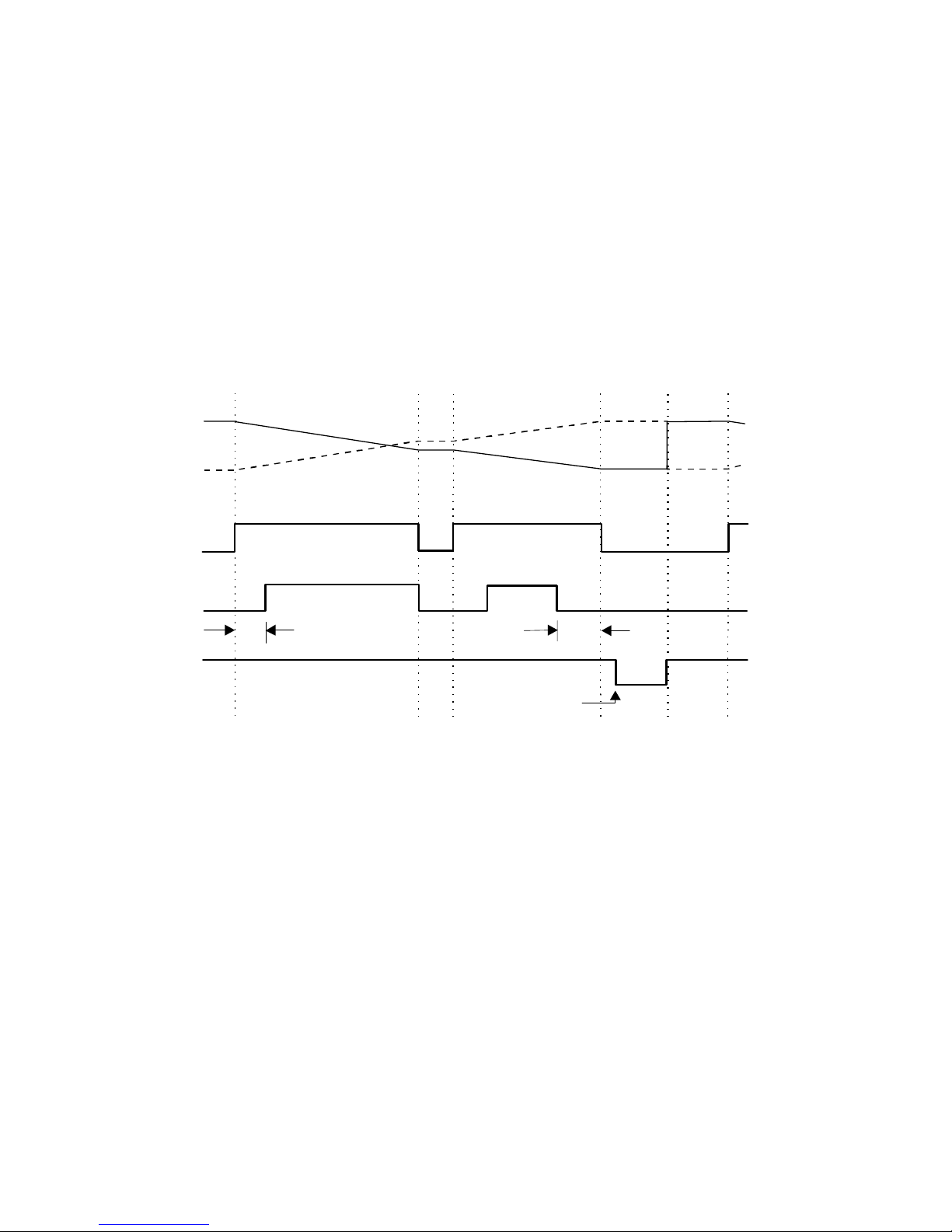
3.2 BATCH OPERATIONS
The Batch Control functions can be programmed during Calibration to operate
in one of two ways :-
1. At the end of the batch, the STOP key must be pressed to reset the Batch
Total. (This must be done before another batch can be started).
Run
PAUSE
Stop Run
Stop
Run
Relay 1
Relay 2
Start Time
Prestop
Quantity
End of
Batch
End of
Batch
Count Down
Count Up
Batch
Quantity
Reached
Page 19
424-M-V1.5
Operation 11
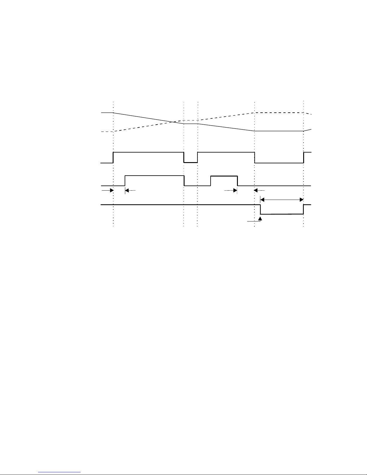
2. If Automatic Reset is programmed, a new batch is commenced each time
the RUN key is pressed.
The Batch Controller can also be programmed, during Calibration, to either
count up from zero on each batch, or to count down from the preset batch
quantity.
Batch
Quantity
Reached
Run
PAUSE
Stop Run Run
Relay 1
Relay 2
Start Time
Prestop
Quantity
End of
Batch
Count Down
Count Up
End of
Batch
Auto Restart
Time
Page 20

424-M-V1.5
12 Operation
3.2.1 Control Relay Outputs
The two output relays can be set up to control either a single valve or a dual
valve with slow stop and/or slow start. Alternatively, the second relay can be
used to control a pump.
The relay operation is shown on the previous two pages.
A time delay between the Start and the time when relay 2 energises can
be programmed to provide a soft startup. The delay can range from 0
(no delay) to 79 minutes and 59 seconds.
A Prestop quantity (i.e. the quantity to the end of the batch) can also
be programmed to provide a slowdown of flow at the end of the
batch, thereby enabling precise quantities to be batched. The Prestop
value is limited by the number of decimal points used for the total
(t.dpt, Cal Menu).
The process can be stopped at any time by pressing the STOP key, whereby
both relays will immediately de-energise. The process can then be aborted
and the Batch Controller reset by pressing the STOP key again, or the process
continued by pressing the RUN key.
If the process is continued and the instrument was previously in the slow
start or main control phases (i.e. not the prestop phase), the timer will be
reset and a slow start will occur with a full time delay to ensure a correct
start up. The totals will not be reset and the batch quantity will remain
unchanged.
t.dpt Max Prestop
0 10,000
1 1,000
2 100
3 10
Page 21

424-M-V1.5
Operation 13
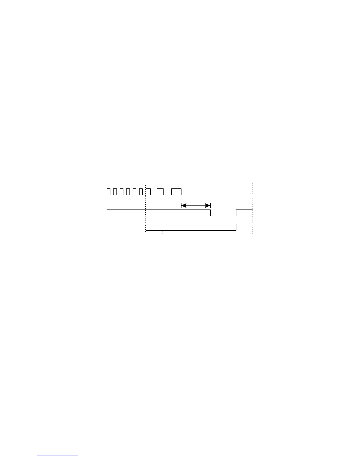
3.2.2 Signal Timeout
The Signal Timeout period defines a time interval which is used to detect if
the flow has stopped. If there is no signal input for a time greater than the
Signal Timeout period, the flow is deemed to have stopped. A Signal Timeout
period has two functions:
� To detect the loss of signal midway through a batch when the
relays are energised. In this case, the Batch Controller will enter a
Flow Alarm condition and de-energise the relays.
� After the preset batch quantity has been reached and the
relays de-energised, some overrun of flow may occur due to
slow valve closure, etc.
In this case the Signal Timeout is used to determine when the flow has
ceased and thereby accurately determine the amount of overrun.
It is recommended that Signal Timeout periods are kept fairly short, but
long enough such that the period is significantly longer than the time
period between successive input pulses from the flowmeter at the minimum
flowrate.
The instrument enables the user to program a time interval of up to 99 seconds
to detect an absence of signal input. If the Signal Timeout is set to 0, this
function is disabled.
Flow Alarm
If the Signal Timeout is set at greater than 0, and loss of signal is detected
midway through a batch, a Flow Alarm condition exists, both relays are deenergised and “FloErr” is displayed on the LCD.
The Flow Alarm condition is maintained until acknowledged by pressing the STOP
switch. The alarm condition is also signalled to the operator by the flashing STOP
LED. Once acknowledged the process can then be reset via the STOP switch or
continued by pressing the RUN key.
With the Model 424, an open collector output on terminal 25 will also switch 'On'
whenever the Flow Alarm condition exists (see Section 3.5).
Page 22
424-M-V1.5
14 Operation
3.2.3 End of Batch
An End of Batch is defined as being when the Batch Quantity is reached, the
flow has stopped and the Signal Timeout period has expired.
If the Signal Timeout is set to zero, the End of Batch is defined as being when
the Batch Quantity is reached, regardless of whether the flow has stopped.
The Batch Controller cannot be reset or restarted until the End of Batch
and similarly, for an RS232/485 interface, data will not be output until the
End of Batch has been determined. Consequently, it is strongly
recommended that the Signal Timeout period be kept fairly short.
End of Batch / Pump Control Signal
An End of Batch signal from an open collector transistor is output on terminal
24, if this terminal has been assigned as an 'End of Batch Signal', sec 5.2, and
the output is identical to the Output Pulse circuit as shown in Section 3.5.
When reaching the End of Batch, the output transistor is switched on, and
will remain in the 'on' state until the next batch is started.
If this signal is set to 'Pump Control' within the Batch menu then the behaviour
of terminal 24 will mimic the status of the Run LED, i.e. its output will turn on
at the Start of the batch and remain on either until the end of the batch is
reached, or the batch is paused. If paused the output will turn on again if and
when the current batch is resumed.
Signal
End of
Batch
End of
Batch
(Timeout = 0)
Batch Quantity
Reached
Reset
Signal Timeout
Page 23

424-M-V1.5
Operation 15
3.2.4 Auto Restart
The Batch Controller can be programmed to continually repeat the batch
process.
This mode of operation is selected during the programming procedure.
The process is started by pressing the RUN key whereby the normal batch
operation is commenced. After reaching the End of Batch (see Section 3.2.3),
the Batch Controller will then wait for a pre-programmed period before
automatically resetting and starting the batch process once again. At the end
of the batch the Run LED will flash amber during the Timeout phase and then
flash green during the Auto Start delay period.
The STOP button can be pressed at any time to interrupt the batching process
and continued using the RUN key. If, however, the process is to be aborted,
the STOP key is again pressed. The Batch Controller is reset and to restart
the auto batching process the RUN key is pressed.
Page 24

424-M-V1.5
16 Operation
3.2.5 Automatic Overrun Compensation
The Batch Controller can be programmed to automatically compensate for
any overrun at the end of a batch.
Typically, this could be due to the slowness of a valve to close or a pump to
stop pumping on receiving a signal from the Batch Controller. The result is
that the batch quantity will always read higher than the batch quantity set.
The Automatic Overrun Compensation can be enabled or disabled during
the Calibration routine. This feature should only be used if the overrun is
repeatable and the meter produces regular pulses for a given flow-rate,
such as with good quality turbine meters and valves.
The user is cautioned against using Automatic Overrun Compensation if
the overrun is erratic, such as may occur with changing back pressures
or sticking valves.
In calculating the amount of overrun to be compensated for, the Batch
Controller uses the overrun of the initial batch. Deliveries are monitored and
AOC is recalculated if the overun was greater than 0.5% of the Set amount
OR if any underrun occured.
The overrun is defined as the difference between the batch quantity set by the
user and the batch total once the flow has stopped.
With Automatic Overrun Compensation, the Signal Timeout must be set to
a value greater than zero.
Once the Batch Controller de-energises both relays, the instrument looks
for a Signal Timeout, indicating that the maximum interval between pulses
has occurred and that the flow must, therefore, have stopped.
AOC is recalibated at every power up. i.e. The first run of any session
from power up will recalculate the amount of overun and then use
this figure until conditions change.
Page 25

424-M-V1.5
Operation 17
3.3 CALCULATION OF RATE AND TOTAL
3.3.1 Frequency Input
The flowrate, R, is calculated as follows:
R = f x H
S
where f is the input frequency in Hz.
H is the timebase of rate and is 1 for seconds, 60 for
minutes, 3600 for hours and 86,400 for days.
S is the Scaling Factor.
The Scaling Factor, S, is equal to the K-factor of the flowmeter expressed in
pulses per unit volume.
The user programs the Scaling Factor and selects the timebase during
the Calibration procedure as detailed in Section 5 of this manual.
Page 26
424-M-V1.5
18 Operation
3.3.2 Filtering
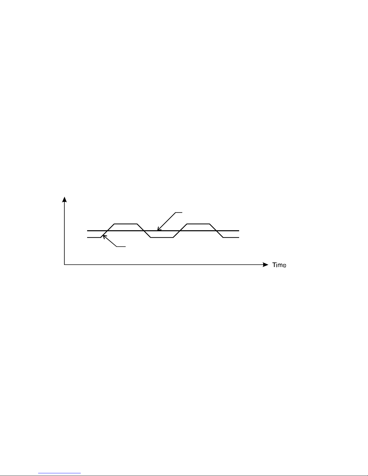
Frequency fluctuations caused by pulsating flow through a flowmeter, often
makes the Rate difficult to read with any precision.
The Batch Controller has a digital filter which will average out these
fluctuations and enable the Rate to be read to four digit accuracy. The ability
to select a suitable filtering level means that highly accurate and stable
readings can be obtained without excessive lag.
When the Rate is retransmitted via the 4-20mA output, the filtering will
also average out any fluctuations on the output.
The diagram below shows a pulsating signal input together with the effect
of filtering.
As a guideline to the degree of filtering to be used, the following table shows
the response to a step change in input. The value, A, is the filter constant
which is programmed during the Calibration routine. The times for the
display value to reach 90% and 99% of full swing are given in seconds, for
different values of A.
Filtered Response
Unfiltered Response
Rate
Page 27

424-M-V1.5
Operation 19
A 90% 99%
1 0 0
2 1 2
4 2 4
6 3 6
10 5 11
15 8 17
20 11 22
Table 1 - Response to a step Input (in
seconds).
Note that if A is set to 1 there is no filtering of the input signal.
Page 28

424-M-V1.5
20 Operation
3.4 TOTAL CONVERSION
The Total Conversion feature enables the rate to be displayed in one
engineering unit (eg. gallons/minute) and the totals to be displayed in
another engineering unit (eg. barrels).
The Scaling Factor is always programmed in the unit relating to Rate, and the
Total Conversion constant is a division factor which can be used to convert the
totals to the different unit. The Total Conversion factor affects the net,
accumulated and gross totals and is limited between 0.01 and 2000.
For Example:
If the Rate is required in gallons per minute:
1. Scaling Factor would be programmed as pulses per gallon.
2. The timebase would be programmed as minutes.
If the Totals are required in barrels:
3. The Total Conversion factor is programmed as 42 (there are 42 U.S.
gallons in a barrel). All totals, including the Batch Quantity and Batch
Total, will now be in barrels.
Some common units are given below together with the Total Conversion
constant (TOTCON) which should be programmed.
Rate* Totals
TOTCON
Gallons (US)/ Barrels (oil) 42.000
Litres/ m³ 1000
ml/ Litres 1000
Mgallons/ Acre-feet 0.32587
* Units per second, minute, hour or day. The timebase is programmed
separately during Calibration.
Page 29

424-M-V1.5
Operation 21
3.5 THE OUTPUT PULSE AND FLOW ALARM
An OUTPUT PULSE is available on terminal 11 for driving remote counters and
produces a pulse each time the Accumulated Total increments by one digit.
For example, if the Accumulated Total has a resolution of 0.01 gallons, a pulse
is produced each 0.01 gallons.
The pulse is a current sinking pulse of approximately 1, 10 or 100mSec
(programmable) produced by an open collector transistor and can sink up to
100mA. The maximum pulse rate is limited to 499 (1mSec), 49 (10mSec) or 4.9
(100mSec) pulses per second and the resolution on the accumulated total must
be set so that the accumulated total increments at less than the available
counts per second.
Note that due to the uneven pulse output spacing on this output, the pulse
output cannot be used to drive rate indicators.
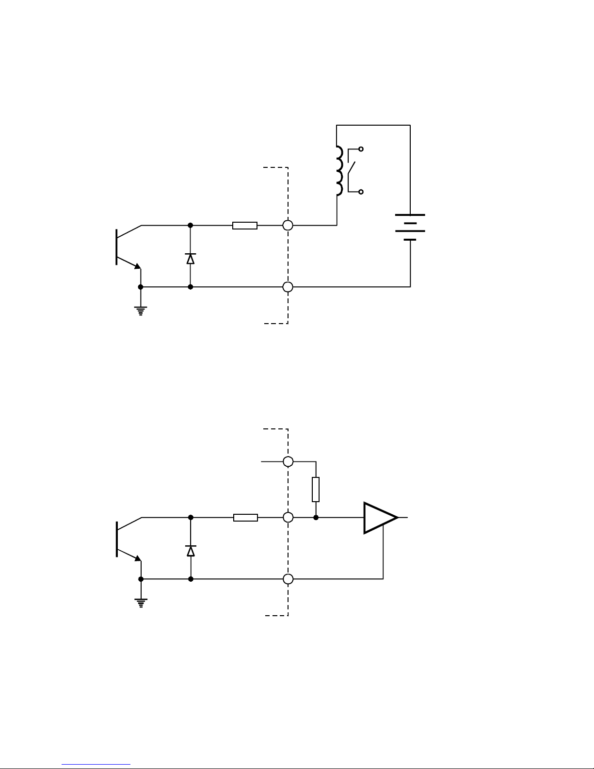
The FLOW ALARM uses an identical circuit to the Output Pulse, and is on
terminal 25.
The Flow Alarm will output an alarm condition if the flow times out during a
batch (i.e. there is no flow registered for a time greater than the Signal Timeout
period, providing the Signal Timeout is greater than 0).
The Flow Alarm output will switch 'on' (i.e. the signal goes low) whenever
an alarm condition exists. The Alarm will switch 'off' (i.e. the signal goes
high) when the alarm is reset by pressing the STOP key.
Page 30
424-M-V1.5
22 Operation
Connection of Output Pulse and Flow Alarm are as follows:
Driving an External Relay or Impulse Counter
Driving a Logic Input such as a PLC or Electronic Counter
Relay or
Impulse Counter
5.6 ohms
33V
Zener
DC Supply
23
DC Supply
Out (8-24V)
5.6 ohms
33V
Zener
External Load
Resistor 10K
Logic Input
26
23
11/25
11/25
25 = Flow Alarm
11 = Output Pulse
Page 31
424-M-V1.5
Comms & Options 23
4. COMMS & OPTIONS
4.1 THE RS232/485 INTERFACE
Circuits for both RS232 and RS485 are provided as standard. They can be
used to interface to both printers and computers.
4.1.1 Hardware
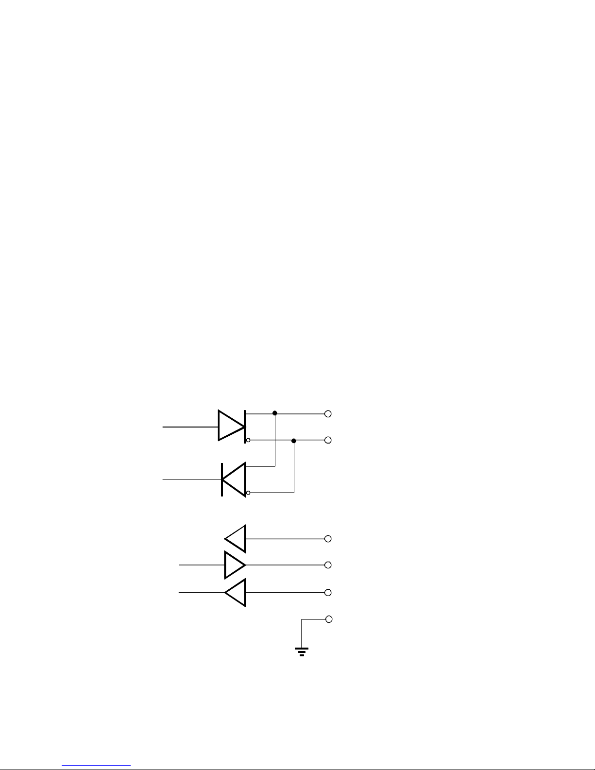
The following diagram provides an overview of the RS232/RS485
communications hardware. Both interfaces are available on the rear
terminal strips and the user can select either one by making the
appropriate connections.
The RS232 interface is primarily used with printers or for simple
communication with a computer over a short distance which ought to be less
than 3m. The RS485 interface is used for communication over a long
distance or in applications requiring multipoint communication. Screened
twisted pair cable should be used for RS485 comms.
10
9
21
22
8
(+)
(-)
RS485 Rx/Tx
Data In
Data Out
Comms Ground
RS232
20 CTS
Page 32
424-M-V1.5
4.1.2 RS232
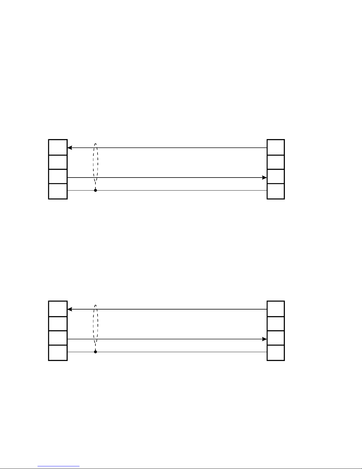
Computers use either 9 pin or 25 pin D type connectors and connections to
each type are shown below. Within the computer serial ports are generally
termed COMx ( where x is the designated port number ).
Connection to Computers with 25 Pin Connectors
Connection to Computers with 9 Pin Connectors
21
20
22
8
2
3
7
424 Series
Instruments
25 Pin
Connector
Computer
Common
Rx
Tx
3
2
5
424 Series
Instruments
9 Pin
Connector
Computer
Common
Rx
Tx
CTS
21
20
22
8
CTS
24 Comms & Options
Page 33
424-M-V1.5
Comms & Options 25
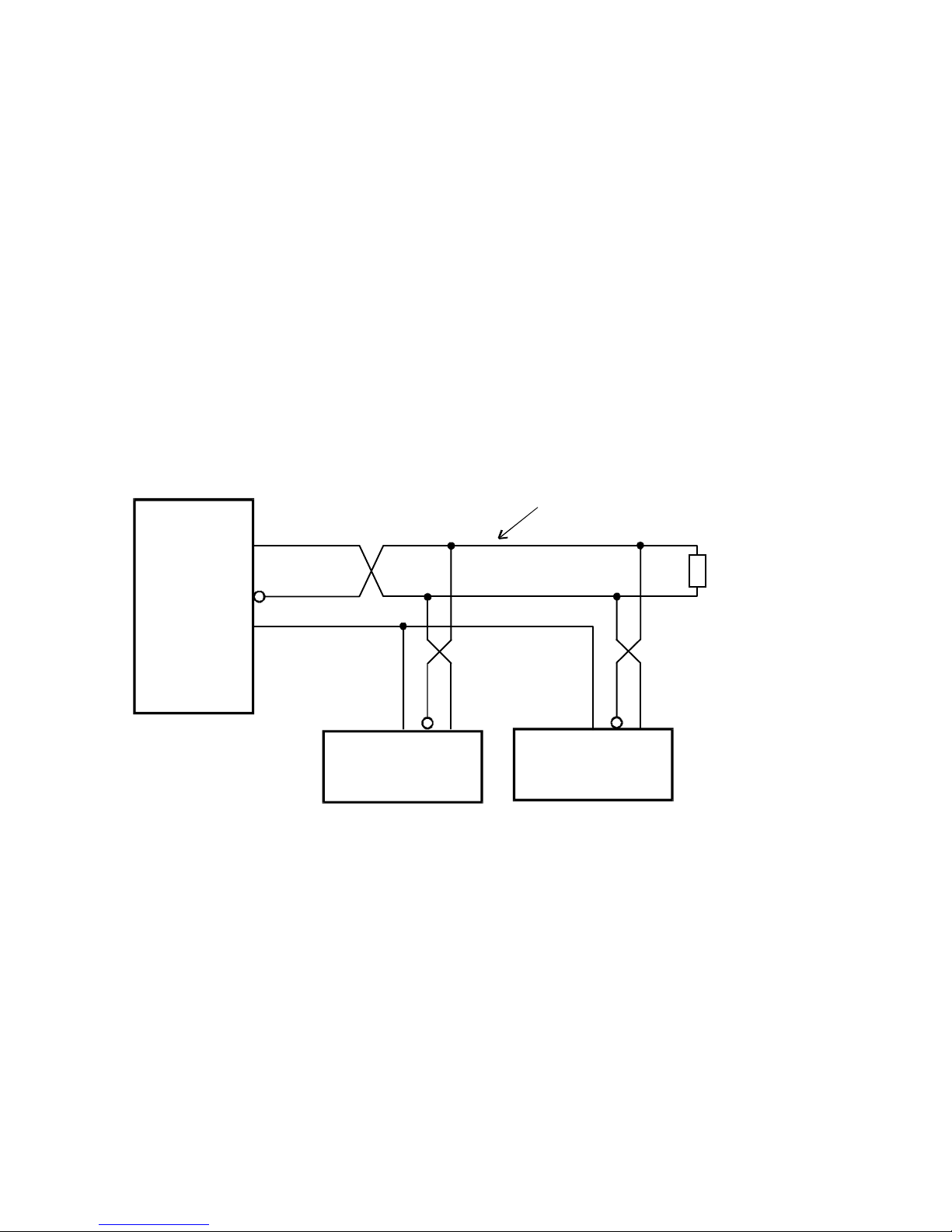
Figure 2 RS485 Interface
Gnd
-
+
424 Series
Instrument
Load
120 ohms
Twisted Pair
Gnd
-
+
424Series
Instrument
4.1.3 Multipoint Communication
Multipoint Communication is a system whereby a number of instruments can
be addressed over a dual twisted pair interface. Note that an external
terminating resistor must be used and should only be connected at the
furthest end of the cable. Up to 32 instruments can be connected to a common
bus using the RS485 interface. When multiple instruments are connected, they
should be 'daisy chained' in a multidrop configuration as shown in figure 2.
Each instrument can be programmed with a unique address which is used by
the Master Controller (e.g. IBM/PC) to identify each instrument. The Controller
will send the address down the line and will alert the relevant instrument.
Subsequent software protocol will control the flow of data between the
Controller and the Instrument.
Host
Computer
Gnd
-
+
Page 34

424-M-V1.5
26 Comms & Options
4.1.4 Real Time Clock
The 424 has a real time clock and enables the time and date to be set and
printed on tickets. The date format can be European (days/months/years) or
USA (months/days/years) while the time is on a 24 hour clock.
Battery backup is provided. If you use the clock function then the
battery will typically need replacing every few years, or more
frequently if extended power downs are a feature of the installation.
The battery is a type CR2032 or BR2032 coin cell. Only type BR2032
should be used in the confrmally coated versions. Refer to Section 7.3
for details of how to change the battery.
4.1.5 Communication Protocol
The baudrate and parity can be programmed during calibration and the user
must ensure that these correspond to the settings on the printer or
computer with which the 424 is communicating.
The software protocols can be selected during Calibration to provide
standard interfaces to a number of printers and computers.
Printers
A ticket is printed each time a batch is complete. Protocols are provided to
drive the following printers:
00. Standard Computer Printer - 80 Col.
(Note that the printer must have an RS232 Serial Interface)
03. EPSON TM290-2 or TM295 Slip Printer - 42 Col.
04. M-Tech roll printer - 32 Col. E.g. MLX-2260, Epson TM-T88V.
05. Porti roll printer - 32 Col.
The tickets can also be printed with a number of different units, including litres
and gallons. The units are selectable from a pre-programmed list. See
Calibration (communication options) for more information.
If an RS232 printer is not used then printer type 00 should be selected on the
Co Opt menu. Do not select Printer type 03 if not connecting a printer.
Page 35

424-M-V1.5
Comms & Options 27
4.2 SOFTWARE PROTOCOL
Standard ASCII Protocol is used within the instrument.
This protocol requires that all command strings be terminated with a
carriage return and the command will only be executed on receipt of the
carriage return.
All messages received from the instrument will be terminated with a
carriage return and a line feed.
Maximum Delay Time
There must be no more than a 2 second delay between successive characters
transmitted from a host computer or terminal. If there is more than a 2 second
delay, the first character after the delay will be accepted as the first character
of a new command, i.e. the buffer receiving the input characters are cleared
after a character timeout has elapsed.
Important Note
Commands sent to the instruments cannot, and should not, be concatenated
together.
4.2.1 Echoing Commands
The instruments can be programmed to Echo all commands it receives back to
the host computer. This is termed Full Duplex and is most often used with a
terminal which is also working in Full Duplex mode.
Alternatively, on these instruments the Echo can be programmed to off and
command strings are not echoed back to the host computer. This is called Half
Duplex and is commonly used in communicating with computers.
Except for test purposes, RS485 communications should only operate in half
duplex mode where the command strings are not echoed back to the host
computer. Full duplex is not suited for automated PC communications when
using RS485, as data contention and corruption would be expected and
therefore should be disabled when using automated 485 communications.
4.2.2 Response Times
The whole string or command is processed at one time after having received a
carriage return. Regardless of the command, the time from the receipt of the
carriage return terminating the command to the first character of the response
is nominally less than 25ms.
Page 36

424-M-V1.5
28 Comms & Options
4.3 COMMANDS AND RESPONSES
Commands sent to the instruments consist of two ASCII characters. If the
command includes a value (such as a batch quantity), the value follows
immediately after the two characters. Commands can be sent in upper or lower
case. Unrecognised commands are answered with an 'Invalid Command'
message from the instrument.
Single Instrument Communications
If a single instrument is connected to a computer, the ID number for that
instrument should be programmed during the instrument Calibration procedure
to:ID = 0
All commands issued by the computer will always be accepted by the
instrument and there is no need for the computer to address the instrument with
an ID number.
Multipoint Communication
Where a number of instruments are connected over a common RS485 bus,
each instrument must have its own unique ID number which can be programmed
during Calibration.
An instrument is selected by the computer sending the command:
IDx
where x is the ID number
Once selected, any of the commands relevant to that instrument can be sent by
the computer, without having to again select the instrument.
It is also possible to determine which instrument is currently selected by
sending the command:
ID
without the value x. On receiving this command the selected instrument will
reply with its ID number.
Page 37

424-M-V1.5
Comms & Options 29
The following commands are recognised by the 424 Batch Controller:
Commands
Idx Select an instrument, where x is the ID number (x will be
accepted with leading zeros). No serial response is returned.
BVxx.x New batch value to be entered. The value xx.x is a variable
length field. All values including the decimal are sent as ASCII
characters. The value is tested against the limits entered
under BATCH in calibration. The Batch Controller must be in
the Delivery Complete status to use this command.
BS Request Status of the Batch Controller. The Batch Controller
will return an ASCII value to indicate the status of the
instrument as follows:
xx xx
ID Status
Status
1 Batch Delivery is complete.
2 Batch is Paused.
3 Batch is in Slow Start cycle.
4 Batch is in Prestop cycle.
5 Batch is in Full Flow cycle (i.e. both relays
energised).
6 Batch Delivery complete but 'End of Batch' has
not yet been reached.
7 Flow alarm detected due to signal timeout midway
through a batch.
8 Batch aborted (Stop pressed twice).
Page 38

424-M-V1.5
30 Comms & Options
BH Stops or Pauses a Batch Delivery. This is the same as pressing
the STOP key on the front fascia. A Batch Status message is
returned on receipt of this command. The BH command can also
be used to acknowledge a flow alarm in the same way as the
STOP key is used.
BR Reset Batch total. The batch total is cleared to zero (if in
count up mode) or to the batch preset quantity (if in count
down mode). A Batch Status message is returned on receipt of
this command. The Batch Controller must be in the Delivery
Complete status to reset the batch total.
BC Start or Resume Batch Delivery. This is the same as pressing
the RUN key on the front fascia. A Batch Status message is
returned on receipt of this command.
T? Request batch totals.
R? Request flowrate.
B? Request batch preset.
On receipt of a 'T?' request, the instrument sends the following:
xx.x
CRLF
Batch Total
Accumulated
Total
Carriage Return
Line Feed
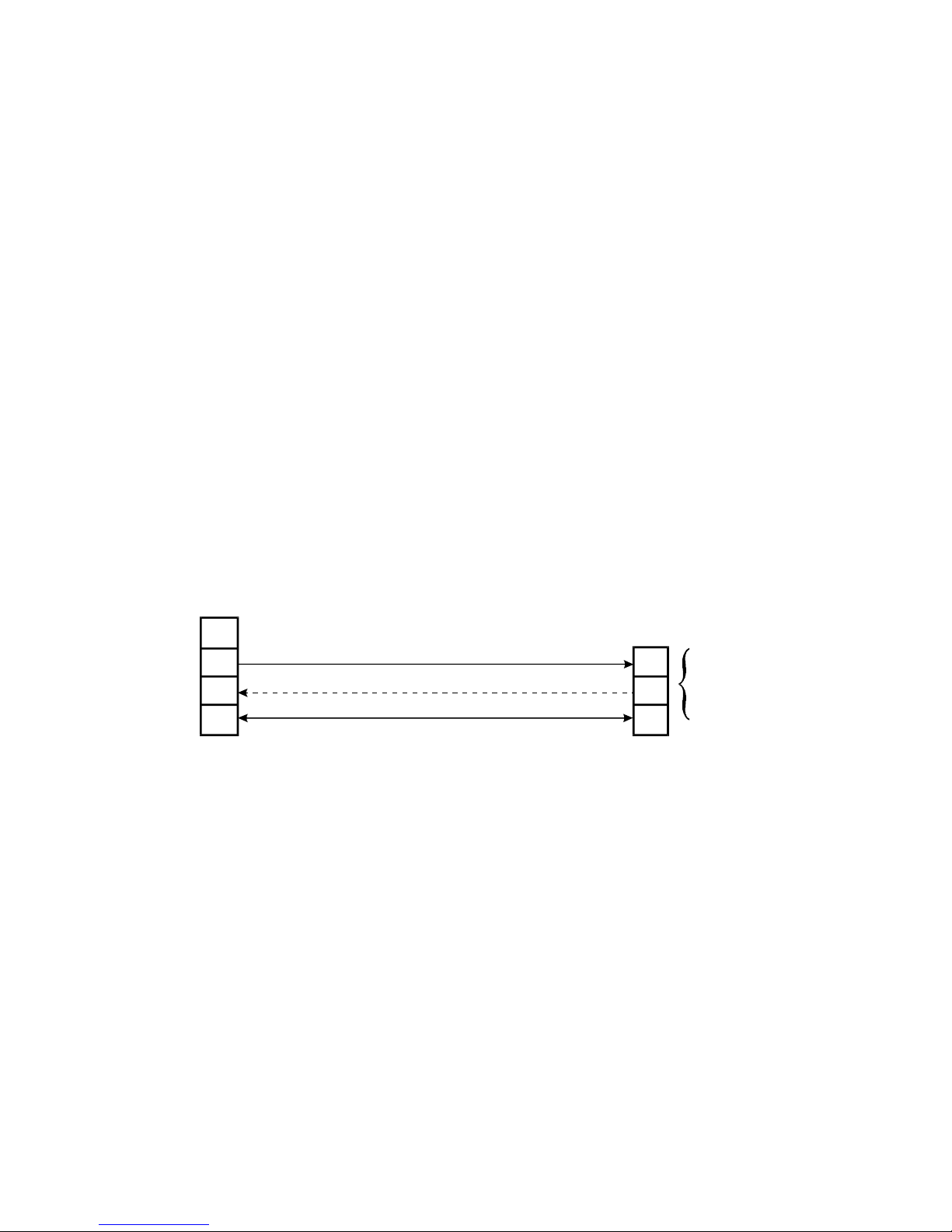
On receipt of a 'R?' request, the instrument sends the following:
Carriage Return
Line Feed
All values are variable length and as displayed on the instrument itself. The
values are transmitted in ASCII with one or more spaces (ASCII Code 32)
between each field.
Commands
xx
xxxx
xx.x
ID No
Ticket no.
xx
xx.x
CRLF
ID
Rate
Page 39
424-M-V1.5
Comms & Options 31
4.4 PRINTER COMMUNICATIONS
The following printers are supported by the Model 424:
PTYPE
00. Standard Computer Printer - 80 Col.
(Note that the printer must have an RS232 Serial Interface)
03. EPSON TM290-2 or TM295 Slip Printer - 42 Col.
04. M-Tech roll printer - 32 Col. E.g. MLX-2260, Epson TM-T88V.
05. Porti roll printer - 32 Col.
PTYPE refers to the menu displayed during the instrument Calibration when the
appropriate printer must be selected. If not connecting a printer then leave
Ptype set to 00.
4.4.1 Hardware Interconnection
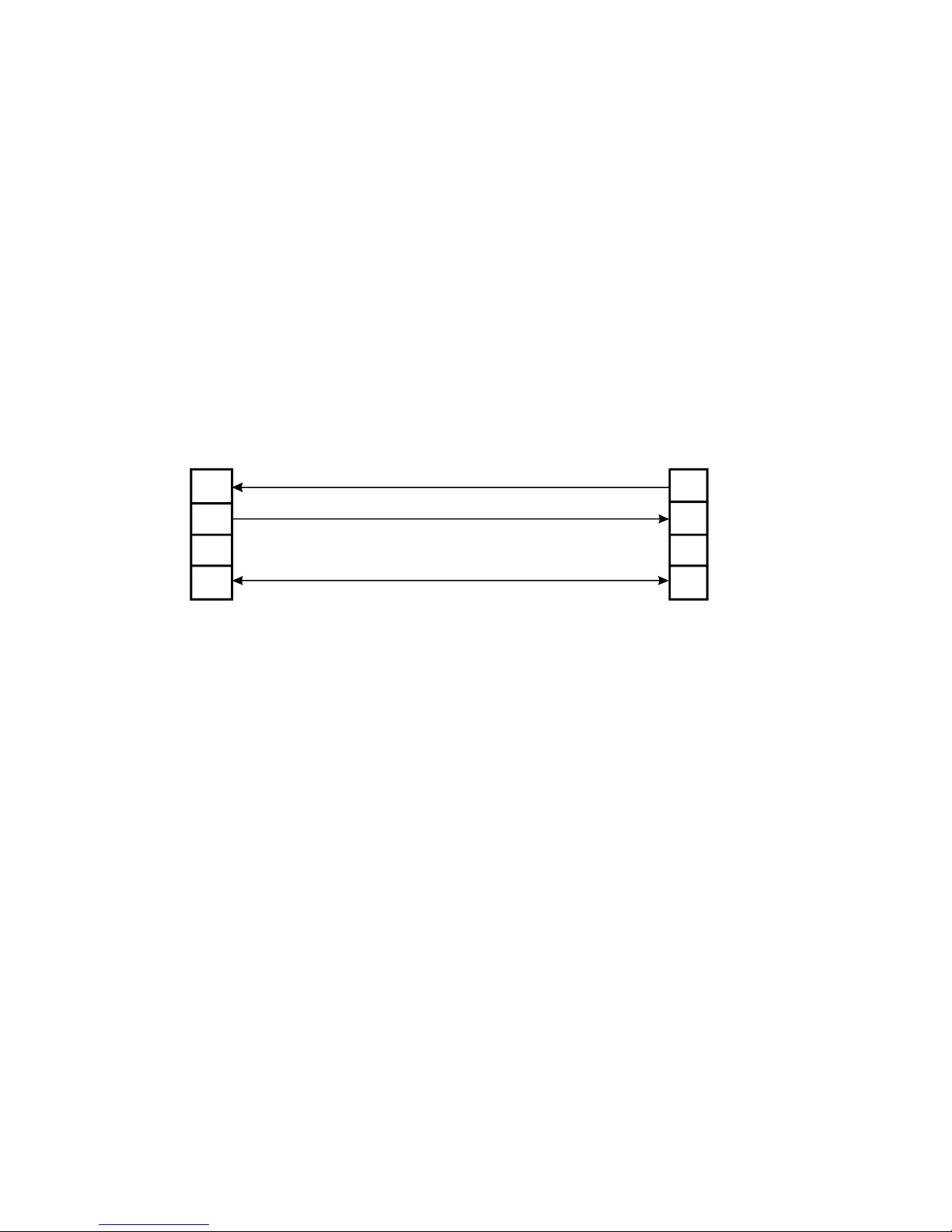
1. Standard Computer Printer
The printer must have a serial interface installed to be able to communicate
with the instrument. Communication via a parallel port on the printer is not
possible.
21
22
20
8
3
4
7
400 Series
Instruments
Printer with
25 Pin Connector
Pin
Signal Ground
Terminal
Data In
Data Out
CTS
Ground
Print Buffer
Full or Request
to Send
Page 40
424-M-V1.5
32 Comms & Options
Normally, it is only necessary to connect the Data Out signal and the
Signal Ground. However, the CTS input on the instrument also allows a
'Print Buffer Full' or 'Request to Send' output from the printer to be
connected to the instrument. This line is used only when the printer
has a very small buffer and there is danger of overwriting the contents
of the printer's buffer (see operating manual for the printer).
In most cases the printer will have an adequate buffer and this line can
be left unconnected.
Epson TM295 and CTM290-2 Slip Printer
The Data In line from the printer must be connected for the interface to
work properly. The instrument interrogates the Epson to ensure that
there is paper in the printer before printing a ticket.
For the Epson CTM290-2 and TM-295, interconnect pins 6, 8 and 20 on
the printer's 25 way connector and when CTS is not used, interconnect
pins 4 and 5.
When the 424 programmed for:
9600 baud
8 bits
and no parity (none)
set all DIP switches OFF on the slip printer.
DIP switches on the printer should only be changed while the printer
power is OFF.
3
4
7
424 Series
Instrument
Epson
CTM290-2
TM-295
Pin
Signal
Terminal
Data In
Data Out
CTS
Ground
2
21
22
20
8
Page 41

424-M-V1.5
Comms & Options 33
4.4.2 Operation
The 424 Batch Controllers will print a ticket on reaching the 'End of Batch' (see
instrument operating manual for a description of End of Batch).
4.4.3 Information Printed
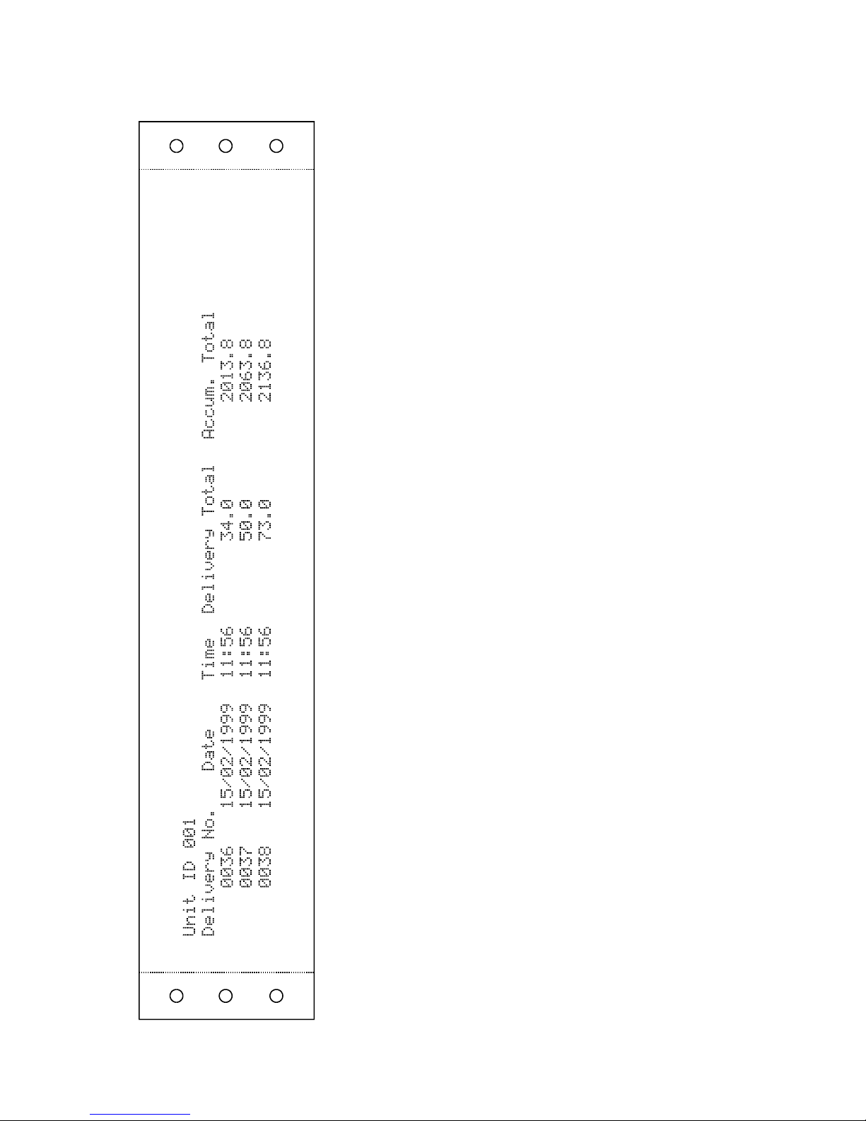
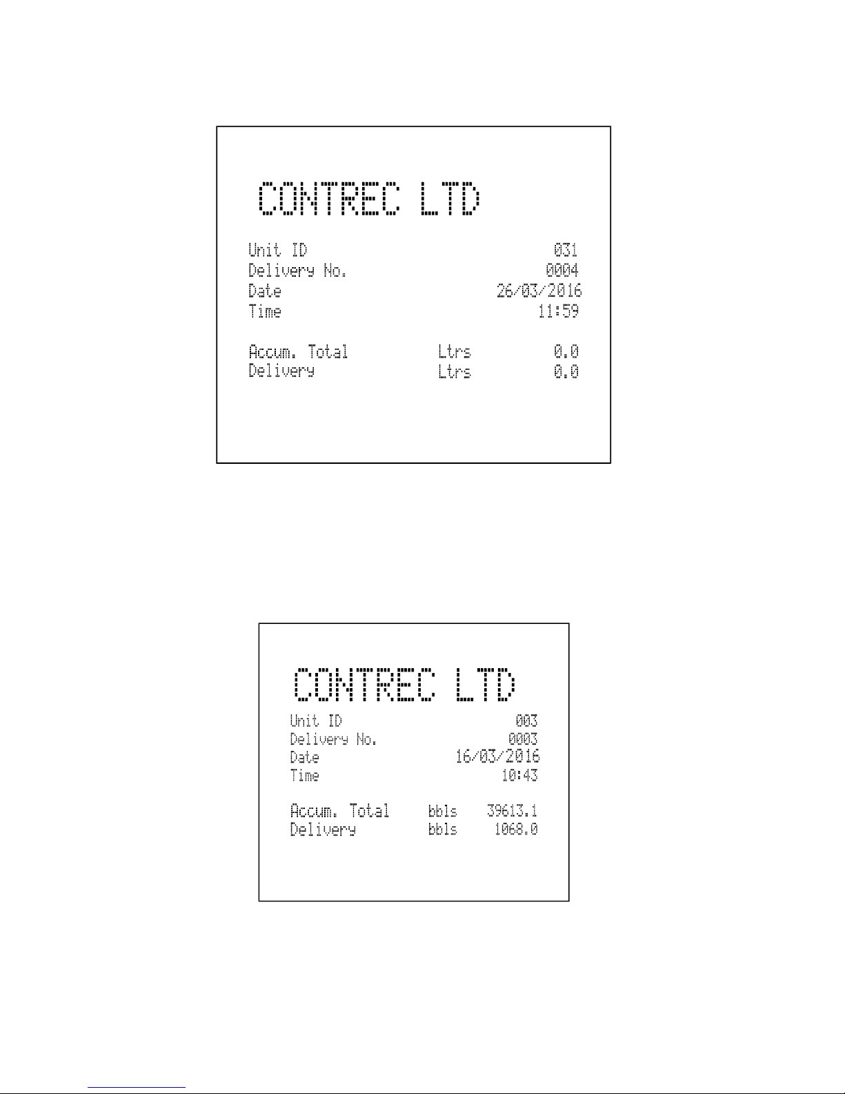
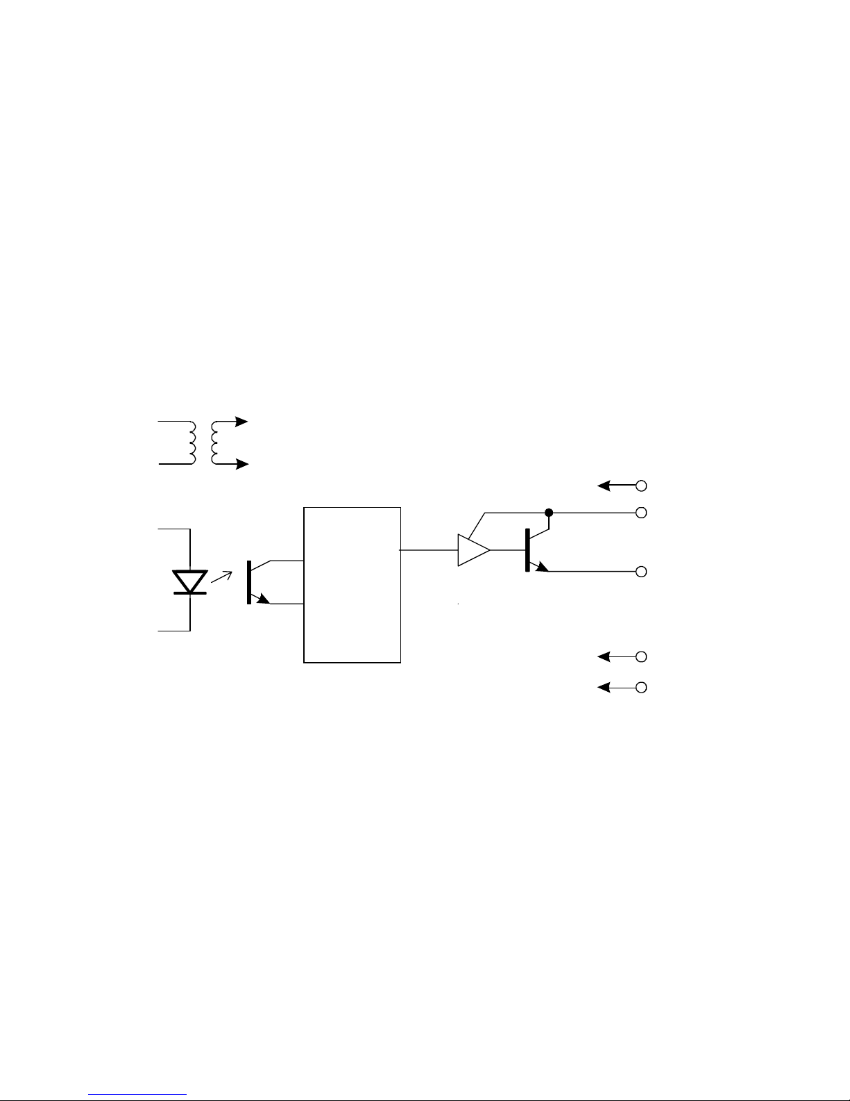
The format with which the data is printed depends on the type of printer
selected. Samples of different printouts are included at the end of this
section.
Each printout includes the following:
1. Header This is a factory programmed header on the ticket
which can show the company or product name.
(Maximum 5 lines, up to 32 characters, dependant on
the printer)
The required header must be specified on ordering
the instrument.
2. Unit ID This is the ID number programmed during
Calibration.
3. Ticket Number The ticket number is a sequential number which
increments and is printed with every ticket. It
enables each ticket to be uniquely identified.
4. Time/Date An internal clock enables the ticket to be printed
with the time & date. The date can be programmed
to print in European (dd/mm/yy) or US (mm/dd/yy)
format.
The remainder of the ticket comprises of the totals as displayed on the front
LCD display. Custom units ( up to 4 characters ) can be specified when a
custom header is requested.
Page 42
424-M-V1.5
34 Comms & Options
Example of a printout for a standard 80 Column
computer printer (not to scale).
No header is shown with this printout.
Page 43
424-M-V1.5
Comms & Options 35
Example of a ticket printed on an Epson CTM290-2 printer (not to scale).
Example of a ticket printed on a Porti Roll Printer (not to scale).
Page 44
424-M-V1.5
36 Comms & Options
Digital to
Analog
Convertor
Opto-Isolation
0V
-15V
6
7
Terminal
3
4
+15V
5
4.5 THE 4-20mA OUTPUT OPTION
The 4-20mA output option provides an analog output of rate as a 4-20mA
current. All output signals are electrically isolated from the instrument power
supply and signal inputs to ensure minimum interference. The 4-20mA is
directly proportional to the displayed rate.
Either 2 wire current transmission is available with the loop powered internally,
or 3 wire transmission from an external loop supply.
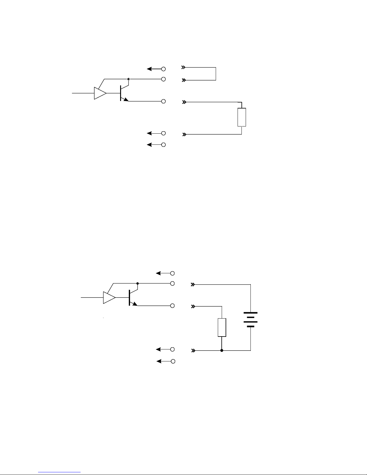
A block diagram of the output is shown below and various methods of
interconnection are outlined on the following pages.
DC to DC
Convertor
Page 45

424-M-V1.5
Comms & Options 37
4.5.1 Load Specification
Maximum load which the output can drive:
Internally powered loop :- +15, 0V 390 ohms
Internally powered loop :- +15, -15V 950 ohms
Externally powered: R = (V-5)/.02
where V is the external loop voltage
R is the maximum load in ohms.
4.5.2 Calculation
Parameters relating to this option are programmed when calibrating the
instrument (see section 5) and provide for:
� Defining the rate which is equivalent to 4mA.
� Defining the rate which is equivalent to 20mA.
By being independently able to set the output range, the instrument can
effectively be programmed to amplify the input signal. In driving chart
recorders, for example, this enables the output to zoom in on a particular
operating area, instead of having to display the full operating range of the
transducer.
For example, 4mA may be set as 0 litres/min and 20mA as 100 litres/min.
However, the user could set 4mA as representing e.g. 10 litres/min and
20mA as representing 120 litres/min.
For rates or displayed values above and below the maximum and minimum
values the output will remain at its 20mA or 4mA level respectively.
It should be noted that the output will be updated every 0.25 seconds in unison
with the display and, between updates, the output value is constant.
Page 46
424-M-V1.5
38 Comms & Options
Two Wire Transmission (Internal Supply)
Link
Load
Terminal
+15V 3
4
5
6
7
390 ohm
maximum
* For driving high impedance
loads (over 390 ohms), terminate
to teminal 7
*
-15V
0V
I (+)
I (-)
Terminal
+15V 3
4
5
6
7
Three Wire Transmission (External Supply)
Load
-15V
0V
I (+)
External Supply
of 15 to 30 Vdc
950 ohm
maximum
I (-)
Page 47

424-M-V1.5
Calibration 39
5. CALIBRATION
The Calibration routine enables the Setup Parameters to be programmed, as
well as enabling the input signals to be checked.
The calibration routine can be entered in two ways:
1. By connecting a wire link (or switch) to the rear terminal strip
across terminals 14 and 19.
Or:
2. By pressing the STOP key and while still holding, press the
DISPLAY key. Both keys must then be held for approximately 6
seconds. This second method of access can be disabled during
the calibration so that it is only possible to enter the calibration
routine via the link across terminals 14 and 19.
The key switch actions during Calibration are as follows:
RUN will change a flashing digit, to the next digit.
DISPLAY will increment a flashing digit or change a
parameter selection.
BATCH SET will reset a flashing digit to zero.
STOP will step through the program sequences.
Note that the arrows in the RUN and DISPLAY key switches indicate that
these switches can be used to change and increment digits respectively.
In stepping through the program sequence, the Parameter Description is
always displayed first, followed by actual value or parameter. When a
value or parameter can be changed, it is always shown as flashing, and the
LED's in the switch panels are lit if that key switch can be used to change a
value.
Page 48

424-M-V1.5
On first entering the Calibration routine, the display will show:
CAL Setup Program parameters (see Section 5.1)
Batch Enter Batch parameters (see Section 5.2)
Co Opt Comms & Option - if installed (see Section 5.3)
Test Check Input Signals (see Section 5.4)
End Exit to Normal Operation
The user can toggle between these modes using the DISPLAY switch and by
using the STOP switch, select the appropriate mode.
To exit Calibration, step through the Setup program, Batch program or
Test program until the end, and press the STOP switch when End is
displayed, (ensure the calibration link is not removed if this method
was used to enter calibration mode).
If power is lost during Cal then any changes made will not be
stored.
40 Calibration
Page 49

424-M-V1.5
Calibration 41
5.1 PROGRAMMING THE SETUP PARAMETERS
Step Display Description Text
Ref
1
CAL
Batch
Co Opt
TEST
END
Select the Calibrate mode to setup
program parameters.
Select Batch to enter Batch Setup
parameters.
Comms and Options (if installed).
Select the test mode to check input signals.
Exit to normal operation.
(5.2)
(5.3)
(5.4)
The following steps are displayed if CAL is selected.
2
REStot
Reset all totals to zero.
xxxxxx
To clear all totals (resettable total
and accumulated) press the reset key.
3
FL INp
Select input signal type: Pulse, Coil or NPS.
(3.2)
6
F dPt
Number of decimal points with which the
Rate is to be displayed between 0 to
0.00000.
7 t.bASE
The Timebase with which the Rate is
calculated must be entered as:
(3.2.1)
SECS
60SECS
HOUR
dAYS
units/second
units/min
units/hour
units/day
5
SCALE
Scaling Factor.
Fact
Enter the scaling factor (K-factor) of the
flowmeter.
4
dbNCE
Debounce, Cut-off <1KHz.
ON/OFF
Select between debounce on or off.
Page 50

424-M-V1.5
42 Calibration
(3.2.2)
Step Display Description Text
Ref
9 TOTCON
A division factor to convert the totals to ( 3.3)
different units from those used for rate (i.e.
gallons/min and barrels).
1
Rate and totals have the same engineering
units.
x.xxxx
Other factors can be programmed between 0.01
and 2000.
10 t.dPt
Number of decimal points with which the
resettable total is displayed between 0 to 0.000.
11
A.dPt
Number of decimal points with which the
Accumulated (non resettable) total is displayed
between 0 to 0.000.
12
PULSE Select the width of the Pulse Output;
1, 10 or 100mSec.
13 dc Out Sets the dc output from 8-24V in 0.2, 0.5
or 1V steps.
14
ACCESS Enable access to calibration routine via the front
keyboard only.
Front Enable access via front keyboard.
No Acc Disable access via front keyboard.
8
FILtER
The filter constant for filtering the rate
display and the 4-20mA output.
1 to 1=
No filtering.
20 20 = H
eavy filtering.
Page 51

424-M-V1.5
Calibration 43
5.2 ENTERING THE BATCH PARAMETERS
Step Display Description Text
Ref
1 BATCH
Co Opt
TEST
END
CAL
Enter Batch Parameters.
Comms & Option (if installed)
Check Input Signals.
Exit to normal operation.
Program Setup Parameters.
(5.3)
(5.4)
(5.1)
The following steps are displayed if BATCH is selected.
2 bAtCH L
xxxxxx
Maximum Batch Size which can be
entered.
Set to 0 if no limit on batch size.
(3.2)
3 AUTO S
OFF
ON
xx:xx
Automatic restart feature.
Disable.
Enable.
If enabled, automatically restarts the
batch xx:xx (minutes:seconds) after the
end of the last batch.
(3.2.4)
4 STARt. t
xx:xx
Slow start time.
Time, in (minutes:seconds), when Relay 2
will energise once the batch has started.
(3.2)
5 PRESt
xxxx
Prestop Quantity.
Quantity at which Relay 2 will deenergise before the end of the batch.
(E.g. If the batch quantity is 100 litres
and Prest is 2 litres, relay 2 will deenergise after 98 litres).
(3.2)
(3.2.1)
Page 52

424-M-V1.5
44 Calibration
Step Display Description Text
Ref
6 COUNt
dn
up
The Batch Total counts Up or Down.
Count down from the batch quantity.
Count up from zero.
(3.2)
7 t OUt The Signal Timeout in seconds.
(Setting to 00 disables this feature). (3.2.2)
8 AOC
En
dIS
Automatic Overrun Compensation.
Note that the Signal Timeout must be
greater than 0 (i.e. enabled) for this
feature to work.
Enable.
Disable.
(3.2.5)
9 AUTO R
OFF
ON
Auto Reset (not displayed if Auto Restart
is programmed - Step 3 above).
Batch Total must be manually reset
before starting the next batch.
The Batch can be automatically reset
and started by pressing only the RUN key.
(3.2)
10 EOb PC
End of Batch Terminal behaviour.
Signal energises at the End of Batch.
Pump Control :- Signal energises when Run
is pressed and de-energises at the end of
batch or when the delivery is paused.
EOb
PC
(3.2)
Page 53

424-M-V1.5
Calibration 45
5.3 PROGRAMMING OPTIONS
Step Display Description Text
Ref
1 Co Opt
Test
End
CAL
Batch
Comms & Options (if installed).
Check the Input Signals.
Exit to normal operation.
Program Setup Parameters.
Set Batch Parameters.
(5.4)
(5.1)
(5.2)
If the RS232/422/485 option is installed, the following will be
displayed:
2 dF
EUR
USA
Date Format.
European (i.e. days/months/years).
USA (i.e. months/days/years).
(4.1)
3 dAtE
xx:xx:xx
Enter date in the format selected.
European or USA.
4
HOUR
xx:xx:xx
Enter time as a 24 hour clock.
Hours:Minutes:Seconds
RS232
Baudrate.
300, 600, 1200, 2400, 4800, 9600, 19200,
57600,115200.
(4)
7
PARITY
NP
OP
EP
Parity.
No Parity.
Odd Parity.
Even Parity.
6 bAUd
xxxx
5
tic no.
xxxxxx
Edits the current ticket number
to be printed.
(4.1)
8 PtYPE xx
00
03
04
05
20
Printer Type or Computer .
None or Standard 80 col Computer Printer.
EPSON TM290-2 or TM295 Slip Printer.
M-Tech 32 column roll printer.
Porti Roll 24 column roll printer.
Computer.
(4.1.5)
Page 54

424-M-V1.5
46 Calibration
Step Display Description Text
Ref
10A
ID NO
00
01-99
Unit Identification Number.
None.
Id Number.
9A
ECHO
ON
OFF
ECHO Commands.
Echo (Full Duplex).
No Echo (Half Duplex).
If RS232 = COMPUTER then RS485 will be un-available.
If RS232 = PRINTER then RS485 will be available for Computer.
Units of measurement printed via 232 Printer.
None.
Litres (Ltrs).
Gallons (Gals).
Barrels (bbls).
Pounds (lbs).
Grams (gms).
Kilograms (kgs).
Tons (tons).
Custom units - factory programmed on request.
9A
UNIT xx
00
01
02
03
04
05
06
07
08
Baudrate for 485.
300, 600, 1200, 2400, 4800, 9600, 19200,
57600,115200.
(4.2)
10A bAUd
xxxx
11A
PARITY
NP
OP
EP
Parity.
No Parity.
Odd Parity.
Even Parity.
RS485 - Only Available for computer when RS232 = Printer.
13A
ID NO
00
01-99
Unit Identification Number.
None.
Id Number.
12A
ECHO
ON
OFF
ECHO Commands.
Echo (Full Duplex).
No Echo (Half Duplex).
Page 55

424-M-V1.5
(4.1)
14
OP 4
xxxx
Flowrate at 4mA.
Enter flowrate.
15
OP20
xxxx
Flowrate at 20mA.
Enter flowrate.
If the 4-20mA output option is installed, the following will be displayed:
16
bLIght
xx
Select the desired Back Light level
00 = off, 05 = Full Brightness.
N.B. - the number of decimal points selected in F dPt - sec 5.1, step 6, interracts
with the OP 4 & OP20 settings. If the number of decimal points selected by F dPt
results in an integer that is too small to display the Alarm or 4-20mA settings
then these values will be restricted to the maximum value which the display can
accomodate within its 6 digits - e.g. 99.9999, 999.999 etc.
Calibration 47
Page 56

424-M-V1.5
48 Calibration
5.4 TEST MENU
Step Display Description Text
Ref
1
TEST
END
CAL
Batch
Co Opt
Check the Input Signals.
Exit to normal operation.
Program Setup Parameters.
Enter Batch Parameters.
Comms and Options (if installed).
(5.1)
(5.2)
(5.3)
The following steps are displayed if TEST is selected.
2
SR x.xx
Software revision number. Displayed for one second.
4
CLOC
xx:xx:xx
Clock.
Time in Hours:Mins:Sec.
3 FREq
xxx.xxx
Input Frequency.
The actual input frequency in Hz.
5 dAtE
xx:xx:xx
Date
Date in the selected format.
6
5u:x.x
Measured 5V system voltage.
7 Ui
:x.x
Measured system supply voltage.
15V on mains supply or 12-28.5V if dc input.
8 Uo
:x.x
Measured dc output voltage.
8-24V as specified in Cal setup.
9 PrnHdr
Print header update from PC. Can only be
performed at the factory.
Page 57

424-M-V1.5
6. INPUT CIRCUITS
This section covers the connection of flowmeter signals.
The Model 424 has a regulated output which can be used to power sensors.
The voltage can be adjusted in the range of 8-24 Volts within the Cal menu
and the output can supply a maximum of 80mA@24V or 1.9W.
6.1 INPUT CIRCUIT FOR THE MODEL 424
The model 424 has an electronically settable input conditioning circuit which
will accept signals from most pulse or frequency producing flowmeters. To set
the signal type enter the Cal menu.
The input will interface directly to:
- Turbine Flowmeters
- Open Collector Outputs
- Reed Switches
- Logic Signals
- Two Wire Proximity Switches.
For open collector outputs, an internal resistor will act as a load. However, the
user must still ensure that the resulting signal will switch at the specified levels.
General Specification
Signal Types: Squarewave, Pulse or Open Collector, <10KHz.
Coil (min 15mV pk-pk) or NPS, <2.5KHz.
Selectable Debounce, cut off <1KHz.
Signal Level: The 'high' signal level must be > 2.0 Volts and must not
exceed 30 Volts.
Installation examples are shown on the following page.
Input Circuits 49
Page 58
424-M-V1.5
50 Input Circuits
Open Collector
Reed Relay Switch
Shield
Signal Ground (-)
1
Frequency
Input (+)
2
Signal Ground (-)
1
2
Signal Ground (-)
Shield
1
2
NPN
PNP
+V
Signal Ground (-)
Shield
1
2
Squarewave, CMOS or TTL
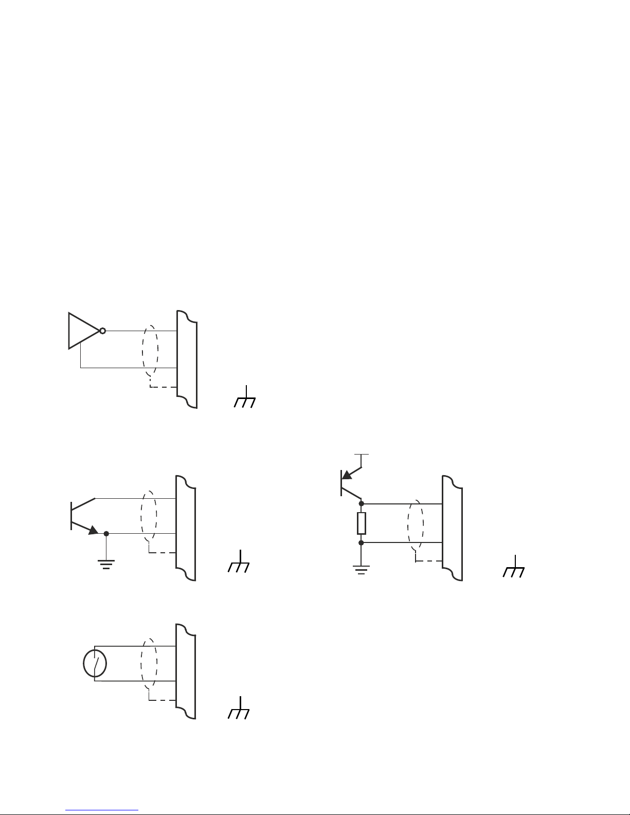
6.2 FREQUENCY INPUT CONNECTION
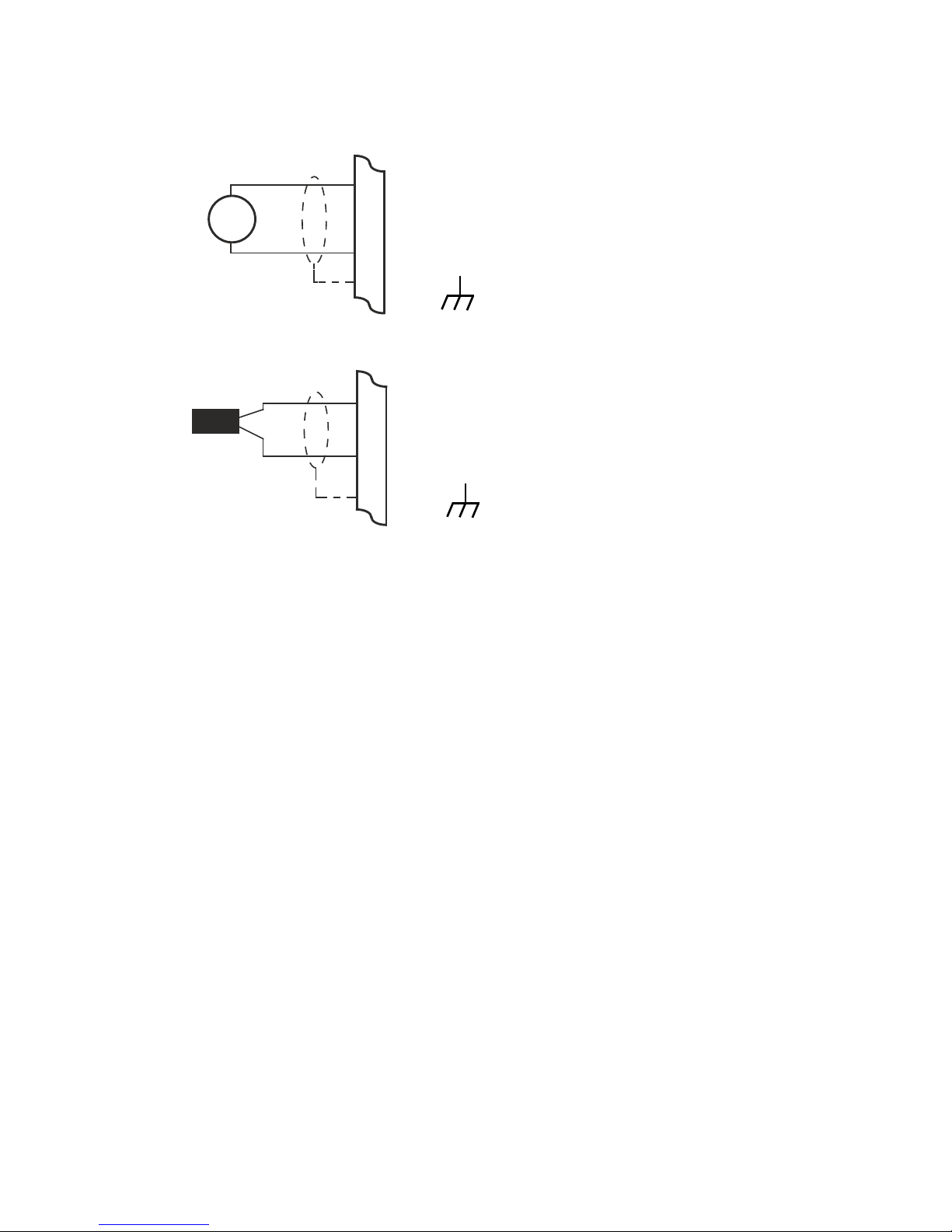
Connect pulse or frequency input signals from devices such as: TTL, CMOS,
open collector, reed relay switch, coil and Namur proximity switch, as shown
below. For better signal integrity, it is recommended to use shielded cable.
For coil inputs twisted pair screened cable is recommended. Coil pickups are
not recommended for long or electrically noisy installations.
Cable screens should be terminated to the case bolt provided on the side of
the instrument. They should never be terminated to DC gnd.
Shield
Frequency
Input (+)
Frequency
Input (+)
Frequency
Input (+)
Page 59
424-M-V1.5
Coils - with 15 millivolts peak to peak AC minimum
Namur Proximity Switch
~
Signal Ground (-)
Shield
1
2
Vo = 8V DC
Shield
NPS
2
TTL - Switching point = 2V. AC input impedance 2.7k.
NPS - Load = 680r.
Coil - 15mV pk-pk min.
Debounce On - Cut off <1KHz.
26
Frequency
Input (+)
Frequency
Input (+)
Input Circuits 51
Page 60
424-M-V1.5
52 Input Circuits
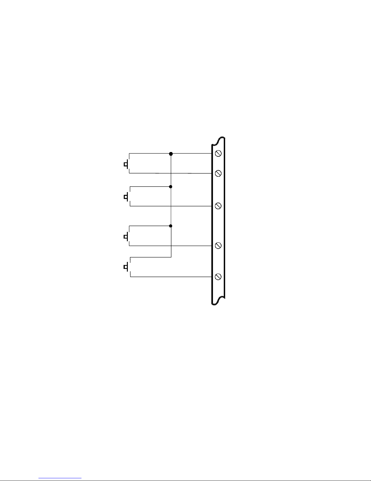
6.3 REMOTE SWITCHES
Remote push-buttons can be connected to the Model 424 to duplicate the
switches on the front panel and to provide remote Start and Stop capability.
On the Model 424, all four switches are taken to the rear terminals.
The switches are wired as follows:
19-Gnd
16
17
15
18
RUN
DISPLAY
BATCH
SET
STOP
Page 61

424-M-V1.5
7. INSTALLATION & MAINTENANCE
7.1 GENERAL
Terminal designations for the Model 424 Batch Controller are given on the
following pages. The cutout hole in the panel should be 5.5" (139mm) wide x
2.6" (67mm) high. Two side clips are supplied to secure the instruments into
panel.
A case earthing point is provided via the mains inlet. Note that this earthing
point is for the case only and there is electrical isolation between this point and
all electronic circuits. For EMC purposes, or when the instrument is connected
to mains, this point must be connected to a good earth.
Disconnection Device :- When powered from a mains supply this unit requires
the provision of a suitable mains isolation device, capable of interrupting both
poles of the supply and meeting your local wiring regulations, to be accessible
near to the installed instrument.
The two output relays are changeover relays and both the 'normally open' and
the 'normally closed' terminals are available on the rear terminal strips.
All relay outputs are totally isolated from the case and from the internal
circuitry.
A Supply Output voltage is provided to power sensors. This output will provide
a regulated voltage of 8 to 24 volts and the voltage is adjustable by means of
the Cal menu. Maximum current is 80mA and the instrument comes with the
voltage factory set to 8 Volts.
The instrument will operate from either 12-28.5 volts DC via terminals 12 and
13, or from a mains supply via the mains inlet. The instrument uses a universal
input switch mode PSU which will accept a mains input of 100-240V, 50-60Hz.
The DC Ground terminal 13 provides a common ground for the 13.5-28.5 Volt
power input. When DC powered terminal 12 provides the positive power input, .
Ground terminal 23 provides a ground return for the 8-24 Volt output and the
pulse output.
It is good practice to use shielded cables for all signal connections to the
Model 424. Cable screens should be terminated to the case bolt provided
on the side of the case. Care must be taken to separate signal cables from
power and relay cables in order to minimise interference.
Installation & Maintenance 53
Page 62

424-M-V1.5
54 Installation & Maintenance
Overall shields should be connected to the case earth at the instrument end
only.
This connection should be as short as possible and connected to the shielding
point provided on the side of the case.
In order to comply with the requirements for Electromagnetic Compatibility as
per EMC-Directive 2014/30/EU of the Council of European Community, this
wiring practice is mandatory.
RC Networks for Interference Suppression
When driving highly inductive loads with the relay outputs, it is recommended
that RC suppression networks (often called 'Snubbers') are used for two
reasons:
� To limit the amount of electrical noise caused by arcing across
the contacts which may, in extreme cases, cause the
microprocessor to act erratically.
� To protect the relay contacts against premature wear through pitting.
RC suppression networks consist of a capacitor and series resistor and
are commonly available in the electrical industry. The values of R and
C are dependant entirely on the load. However, if the user is unsure of
the type of snubber to use, values of 0.25uF and 100 ohms will usually
suffice. Note that only mains rated, UL approved RC suppression
networks should be used.
The basic principle of operation is that the capacitor prevent a series of
sparks arcing across the contact as the contact breaks. The series resistor
limits the current through the contact when the contact first makes.
Page 63

424-M-V1.5
7.2 WIRING DESIGNATIONS FOR THE 424
Terminal Model 424
1 Flow Common (-)
2 Flow Signal Input (+)
3 +15V (option)
4 4-20mA Power in - link to 3 or ext PSU (option)
5 I (+) (option)
6 Either I (-) 0V return - loads up to 390ohm (option)
7 Or I (-) -15V return - loads up to 950ohm (option)
8 RS232 Signal Ground
9 RS485 (-)
10 RS485 (+)
11 Pulse Out
12 DC Power Input (12-28.5 Volts dc)
13 DC Ground
14 Calibration Link
15 Run Switch
16 Display Switch
17 Batch Set Switch
18 Stop Switch
19 Switch ground
20 CTS in
21 Rx (424 Data in)
22 Tx (424 Data out)
23 Pulse & Power Out Ground
24 End of Batch / Pump Control
25 Flow Alarm
26 DC Power Out (8-24 VDC)
1-13, Lower Deck - GREEN. 14-26 Upper Deck - ORANGE,
numbered left to right.
Terminal Relays
27 Relay 1 - Common
28 Relay 1 - Normally Closed
29 Relay 1 - Normally Open
30 Relay 2 - Common
31 Relay 2 - Normally Closed
32 Relay 2 - Normally Open
Installation & Maintenance 55
Page 64

424-M-V1.5
7.3 MAINTENANCE
Occasionally it may be necessary to open the unit in order to change the Real
Time Clock battery or change the fuse. No other service operations are
permitted.
In order to perform these operations and maintain safety it is essential to follow
the instructions below.
Disassembly.
1. Power down. Remove all wiring plugs from the unit.
2. Remove the four securing nuts, located in each corner on the rear of the
unit.
3. Remove the front and back panels. You will now have access to both the
fuse and battery holder.
Fuse Replacement.
Fuse type - UL approved, 1AT, 5x20mm, ceramic.
The fuse is located in the rear left corner of the PCB. Remove the fuse in its
carrier and replace with a new one to the above specification.
Battery Replacement.
RTC Battery type - Conformal coat “C” version Panasonic BR2032 coin cell only.
Non Conformally coated versions :- BR2032, CR2032, Sony or Panasonic.
The battery is located at the front of the PCB. Release the battery by gently
pressing on the tab at the left hand side of its holder. Click the fresh battery in
place.
Re-assembly.
1. Replace the front and back panels.
2. Insert the four securing nuts and tighten them.
3. Re-connect all wiring plugs in their original postions. Power up.
56 Installation & Maintenance
Page 65

424-M-V1.5
Trouble Shooting 57
8. TROUBLE SHOOTING
Batch Controller does not reset.
The Signal Timeout has been set to an excessively long period and has
not timed out at the end of the last batch.
Batch will not start or relay 1 will not close.
Ensure that the instrument has not timed out as controlled by the
Signal Timeout and that a Flow Alarm condition does not prevail.
Pressing the Stop switch will cancel this condition. Check for a fault
on the flow input before restarting.
Batch Controller stops midway through a batch.
This could be due to the Signal Timeout having timed out. Check for a
fault in the system. Ensure that the Signal Timeout period is significantly
longer than the period between pulses from the flowmeter at the
minimum flowrate.
No display.
Check power to the instrument.
All 888888 displayed.
The Batch Controller will display all eights on power up for 4 seconds as
a display test. If it continues to display all eights after this period, this
is symptomatic of the power supply voltage being low. Check the
power input voltage.
Not counting.
If the Batch Controller does not count with the flowmeter
connected and flow passing through it, first check the connections
and then ensure that the input type (TTL, Coil, NPS & Debounce
setting) of the instrument are set correctly, as per Section 5.
It is possible to manually test the input circuit of the Batch Controller
by setting the input configuration for a TTL input (see Section 5) and
pulsing across the signal (+) and (-) with a wire link. When doing this,
the scaling factor should be set to 1 and the resolution to whole
numbers.
Page 66

424-M-V1.5
58 Trouble Shooting
Counting erratically.
This can be caused by two factors:
- setting the input circuit incorrectly,
- lack of shielding on the input.
Shield the input signal with the shield earthed at the Batch Controller
only.
Instrument acting erratically.
Erratic operation can be the result of severe electrical
interference.
Considerable attention has been given to designing the Batch
Controller to withstand electrical interference.
However, in extreme cases, loads may be encountered which
are exceptionally inductive and may require additional
protection. One measure is to use an RC Suppression Network
as described in Section 7.
Another remedy for this problem is to use an isolating relay to switch
the load, and use the Batch Controller to drive the isolating relay. The
isolating relay should be mounted away from the Batch Controller and
from signal wiring.
No end of batch, pulse output or flow alarm.
This fault is usually caused by lack of a pullup resistor or load on the
output. The outputs themselves have no internal pullups and rely on
an external load.
Page 67

424-M-V1.5
8.1 ERROR CODES
The instrument has extensive self test facilities and will display an error
message if it detects an invalid condition.
Error Codes
Input Errors
FloErr Signal Timeout (see Section 3.2.2).
Output Errors
PrnErr Communications error - Printer fault, Epson TN290-2, 295, P tYPE 03
only. Check that the printer is connected, switched on and not out of
paper. To cancel press and hold Stop. This will cancel the error until
the unit is powered off and on again.
Trouble Shooting 59
Page 68

60 Index
Index
4
4-20mA output 36
A
Access 39, 42
Accumulated Total 9, 21
Auto Reset 8, 44
Auto Restart 15, 44
Automatic Overrun
Compensation 16, 44
B
Batch Limit 9
Batch Set 7
BATCH SET 39
Battery 26
Battery Backup 6
Baudrate 45, 46
C
Calibration 39
Clock 26
Communication Protocol 26
Computer 23, 45
Control Functions 10
Control Relay 12
Count Down 10, 44
Count Up 11, 44
D
Date 45
DC Input Voltage 6, 48
Decimal Points 41, 42
Dimensions 4
Display Key 7, 9
Displayed Information 9
E
Earthing Point 53
Electrical Noise 54
End of Batch 10, 14, 44
Error Codes 59
F
Filtering 18, 42
Flow Alarm 13, 21
Frequency Input 17, 50
Frequency Range 4
Front Panel Operation 7
G
Ground 53
I
Inductive Loads 54
Input Circuits 48
Input Impedance 51
Interference 53, 54
Introduction 1
Isolation 53
K
Key Operation 7
K-factor 17, 20, 41
L
Limit on Batch 9, 43
Logic Signals 49
Page 69

Loss of Signal 13
M
Mains 4, 53
Model Number 3
Multipoint Communication 25
N
Namur Sensors 50, 51
Non Volatile Memory 6
NPS 41, 49, 51
O
Open Collector Outputs 49
Operating Temperature 4
Operation 6
Options 36
Output Pulse 21
Output Relays 12, 53
Overrun 13, 16, 44
P
Parity 26, 45
Power Requirements 4
Prestop 10, 12, 43
Printer 26, 45, 46
Pulse Output 21, 42
Pump Control 14, 44
R
Rate 9, 17
Reed Switches 49
Regulated Voltage 53
Remote Counters 21
Remote Push-buttons 52
Resetting 8
Response 18
RS232/485 Interface 23
Run Key 7, 8
S
Scaling Factor 41
Scaling Range 4
Setting the Batch 7
Setup Parameters 39, 41
Signal Timeout 13, 21, 44
Slow Start 12, 43
Slow Stop 12
Snubbers 54
Specification 4
Starting 8
Stop Key 8, 12
Stopping 8
Supply Voltage 48
Switching Current 4
Switching Power 4
T
Tickets 26
Time 26, 45
Time Delay 12
Timebase 17, 41
Total Conversion 20
Trouble Shooting 57
Turbine Flowmeters 49
W
Wiring 55
Index 61
Page 70

424-M-V1.5
This page has been left intentionally blank.
 Loading...