

Page 1

212-M-V2.1
HEAT CALCULATOR
MODEL 212
June 2017
Page 2

212-M-V2.1
Page 3

212-M-V2.1
CONTENTS
1. Overview 3
1.1 Model Number Designation 5
1.2 Conversion Factors 6
2. Specification 7
3. Operation 11
3.1 Display Operation 13
3.1.1 Normal Operation 13
3.1.2 Charge/Discharge Operation 17
3.1.3 Peak and Off-Peak Operation 18
3.2 Checking Set-up Parameters 19
3.3 Units of Measurement 24
3.4 Frequency Cut-off 25
3.5 Offset Functions 26
3.6 Operating Modes 27
3.6.1 Heating 27
3.6.2 Cooling 27
3.6.3 Heating/Cooling 27
3.6.4 Charge/Discharge 27
3.7 Peak and Off-Peak 28
3.8 Logging 29
4. Communications 30
4.1 Meter-bus 31
4.2 Infra-red Communications Link 33
4.3 RS485 with Modbus RTU Protocol 34
4.3.1 Hardware 34
4.3.2 Protocol 34
4.3.3 Bus Address 35
4.3.4 Function Codes 36
4.3.5 Exception Response 36
4.3.6 List of Data Registers 37
Page 4

212-M-V2.1
5. Set-up Mode 42
6. Input & Output Connections 48
6.1 Flowmeter Input 48
6.2 RTD Input 52
6.3 Power Supply 53
6.4 Pulse Output 54
6.5 Alarm Relay Outputs 56
6.6 4-20mA Output Option 58
7. Installation 60
7.1 Wall Mounting 60
7.2 Panel Mount Version 62
7.3 Removing the Front Panel 63
7.4 Verification Seal 65
7.5 Wiring Practices 66
7.6 Terminal Designations 68
Index 69
Page 5

212-M-V2.1
Overview 3
1. OVERVIEW
The Model 212 Heat Calculator is designed to measure the energy consumed
in both heating and cooling (air conditioning) systems. The instrument is
normally supplied complete with temperature probes and power supply, and
will interface to a wide variety of flowmeters, including positive
displacement and inferential water meters, magnetic flowmeters with pulse
outputs, turbine flowmeters & paddlewheel flowmeters.
The Model 212 measures the temperature in the feed and return flow lines and
uses this information to calculate the density and enthalpy of water. By also
measuring the volume of water flowing in the system, the Model 212 will then
determine the energy used. Power is calculated as:
P = V x ᵨ x (h
TV
- hTR)
where P = Power (W)
V = Volumetric Flow rate (m3/sec)
ᵨ = Density (kg/m
3
)
hTV= Specific Enthalpy (J/kg) at Feed Temperature
hTR= Specific Enthalpy (J/kg) at Return Temperature
The Model 212 is designed to be used in typical water heating or cooling
systems where pressures do not exceed 16 bars.
The temperature in both the feed and return lines is measured via two
PT100 resistance temperature devices (RTDs). For maximum accuracy, four
wire RTDs should be a matched pair, Class A to IEC 751 standard.
The Model 212 complies with OIML R75 and EN1434 standards and
includes Meter-bus and RS485 (Modbus RTU) communication links.
The Model 212 includes separate peak and off-peak registers as well as the
ability to compute charge and discharge energy in systems where heat may be
stored in underground tanks.
The Model 212 provides pulse output with programmable pulse width from 10
to 500ms.
Page 6

212-M-V2.1
4 Overview
The Model 212 has a highly accurate built-in real time clock (2ppm typ) to
keep track of logging, peak-on/peak-off points, etc. In case of a power
failure, the real-time clock is able to keep running for two days with a ±1
minute accuracy, typically.
RoHS Directive: 2011/65/EU
EN 50581:2012 :- Technical documentation for the assessment of electrical and electronic
products with respect to the restriction of hazardous substances
EMC Directive: 2014/30/EU
EN61326:2013 :- Electrical equipment for measurement, control and laboratory use – EMC
requirements : Residential, Commercial & Light Industry Environment & Industrial
Environment.
Low Voltage Directive: 2014/35/EU
EN61010:2010 :- Safety requirements for electrical equipment for measurement, control and
laboratory use.
In order to comply with these standards, the wiring instructions in Section 7.5
must be followed.
Page 7

212-M-V2.1
Overview 5
1.1 MODEL NUMBER DESIGNATION
Model 212 . 2 0 E 8 S
Mounting
Panel Mount 1
Wall Mount 2
Options
No Options 0
4-20mA Output 1
Power
12VDC Power N
European Adaptor
(220 VAC) E
UK Adaptor
(220 VAC) U
USA Adaptor
(110 VAC) A
Australian Adaptor
(240 VAC) H
Temperature Sensor
None 0
85mm pipe 8
120mm pipe 1
210mm pipe 2
Compliance
EN1434 S
Page 8

212-M-V2.1
6 Overview
1.2 CONVERSION FACTORS
1 kWh = 3.600 MJ
1 MJ = 0.27778 kWh
1 m3 = 1000 litres
1 US gal = 3.785 litres
1 ft3 = 7.4805 US gal
1 kBTU = 1.0551 MJ
1 Ton x Hour (Refrigeration) = 12,000 BTU
1 therm = 100,000 BTU
1 Calorie = 4.1868 Joule
Note: kBTU are used on the Model 212 display and mean BTU x
1000.
Page 9

212-M-V2.1
Specification 7
2. SPECIFICATION
General
Energy Display units: kWh, MWh, MJ, GJ, therm, BTU x 1000, tons x
hours or days (refrigeration), Cal, KCal, MCal.
Maximum Thermal Power: 3000 MW.
Accuracy Class: OIML R75 Class 4, EN1434.
Measurement Time: 0.5 sec time interval.
Environmental Class: EN1434 Classes A & C.
Ambient Temp Range: 0°C to 60°C.
Storage Temp Range: -20°C to 70°C.
Temperature Measurement
Type of Sensor: Pt100 to IEC 751, matched pair, Class A.
Temperature Range: -10°C to 220°C.
Temperature Difference: 1K to 200K.
Approved Temp Range: 1°C to 200°C.
Approved Temp Difference: 3K to 199K.
Measurement Time: 3 sec time interval.
Display
Type: LCD with 7 digit numeric display and 11
character
display.
Digits: 15.5mm (0.6") high.
Characters: 6mm (0.24") high.
Page 10

212-M-V2.1
8 Specification
Flowmeter Input
Type: Frequency or Pulse between 0.01Hz to 20kHz.
Default low frequency cut-off is 0.25Hz.
Signal Type: Pulse, open collector, reed switch,
proximity switch or coil.
K-factor range: Programmable between 0.001 to 999,999.9
pulse
per litre, m
3
, US gallon or ft3.
Location: In either the feed or return lines.
Temperature Sensor (RTD) Input
Sensor Type: Pt100 to IEC 751, matched pair, Class A.
Connection Type: Four wire.
Location: Two RTD inputs, one for the feed and a second
for the return lines.
Linearisation: Built in RTD linearisation.
Temperature Range: -10°C to 220°C.
RTD Cable Length: < 50m.
Pulse Out
Pulse Width: Programmable: 10, 20, 50, 100, 200 or 500ms.
Type: Open collector will sink up to 100mA.
30Vdc Maximum.
Function: Volume or Energy (scaled).
Frequency: 1 pulse every preset number of units of energy
or volume total.
Power Requirements
dc Power: 12 to 24V dc @ 100mA maximum.
ac Power: Supplied via a power adapter.
Page 11

212-M-V2.1
Specification 9
Construction
Enclosure Material: ABS/Polycarbonate.
Colour: Light beige.
Protection: Sealed to IP67 (Nema 4X).
Mounting: Wall mounting or panel mounting.
Dimensions: 152mm (6.0") wide x 98mm (3.9") high x
43mm (1.7") deep.
Alarm Output (not available if 4-20mA Output Option is installed)
Type: Two solid state opto-isolated relays which
will sink up to 250mA. 30V dc maximum.
Function: High and low alarms
individually programmable as unsigned
values, for volumetric flow rate, energy
flow rate, feed temperature, return
temperature or temperature difference.
4-20mA Output Option
Function: Volumetric flowrate, energy flowrate,
feed temperature, return temperature
or temperature difference.
Output Range: 2.0mA to 22.0mA.
Linearity: 0.02% of span.
Accuracy: 0.1% of span.
Response Time: 0.5 seconds to 99%.
Maximum Output: Vdc -6V.
Page 12

212-M-V2.1
10 Specification
RS485 Option
Data Transmitted: Volume and energy totals, peak power,
temperatures.
Baud rate: 300 - 9600 baud.
Parity: Odd, even or none.
Stop bits: One or two stop bits.
Bus Address: Programmable for multiple instruments on
the same bus.
Protocol: Modbus RTU.
Meter-Bus
Type: Conforms to CEN/TC176 Meter-bus standard.
Protocol: IEC 870-5.
Page 13

212-M-V2.1
Operation 11
3. OPERATION
The Model 212 has three display modes:
1. Display of normal energy and flow information
This information is available by pressing the DISPLAY key.
Where appropriate Accumulated Totals can be displayed by
pressing the ACCUM TOTAL key.
2. Checking Set-up Parameters
By pressing and holding the DISPLAY key for about 5 seconds,
the instrument will enter the parameter set-up routine and
allow all set-up parameters to be checked but not changed.
The DISPLAY key is used to step through the parameter list.
3. Set-up Parameters
By removing the bottom cover strip of the instrument (see Section 7),
the set-up switch becomes visible. Pressing this switch will put the
instrument into the set-up mode, whereby all parameters can be
programmed using the DISPLAY, < and û switches.
The LCD display has 7 numeric digits with 11 alphanumeric characters along
the bottom. The alphanumeric characters are used to display the parameter
and units.
Page 14
212-M-V2.1
12 Operation
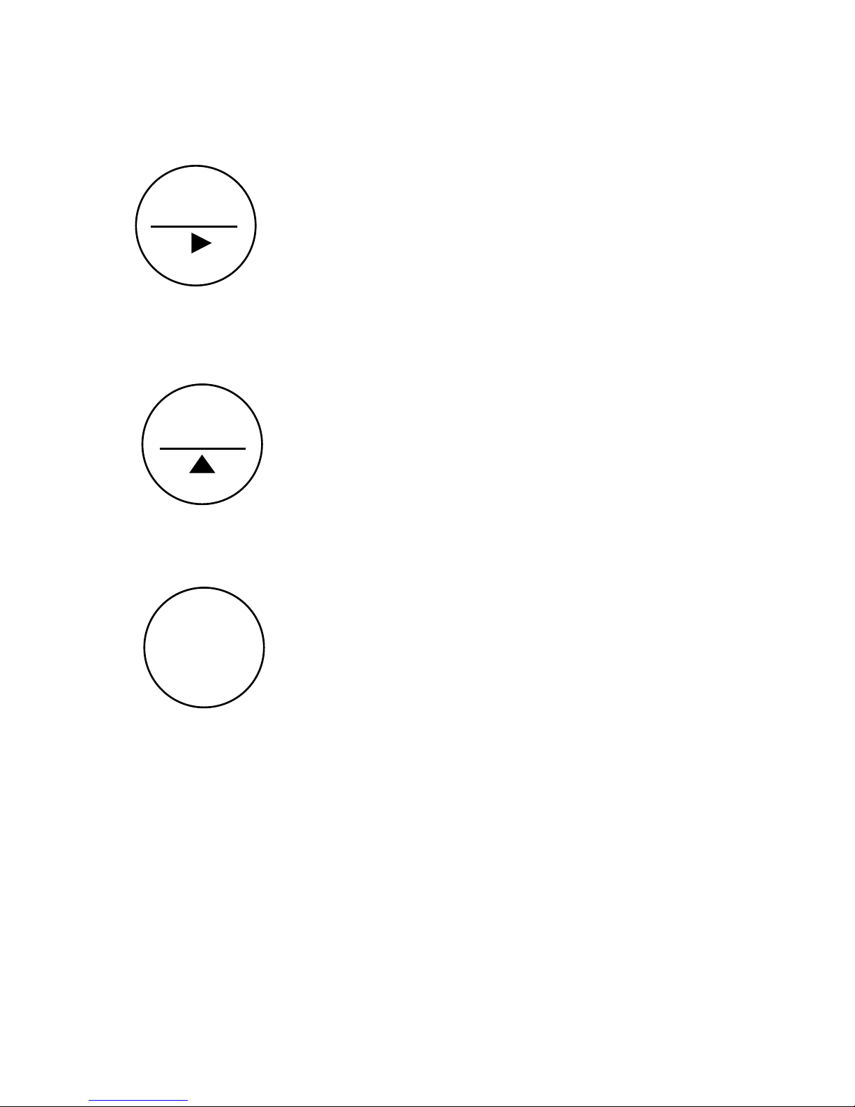
Three key switches provide the following functions:
Displays the accumulated (non-resettable) totals
for Energy, V olume, operating time (elapsed
time) and Energy total for log entries.
Also changes digits, decimal point or units
when entering the set-up parameters. A
flashing digit, decimal point or unit will
indicate that the parameter can be changed.
If the Reset function is enabled during set-up,
the RESET key, when held for 5 seconds, will
reset all totals and the operating time.
Also increments the digit, changes decimal
point position, steps through units when
entering set-up parameters and steps through
individual log entries.
Used to change the display to the next parameter.
Also steps through display modes when held for
5 seconds.
RESET
DISPLAY
ACCUM
TOTAL
Page 15
212-M-V2.1
Operation 13
3.1 DISPLAY OPERATION
3.1.1 Normal Operation
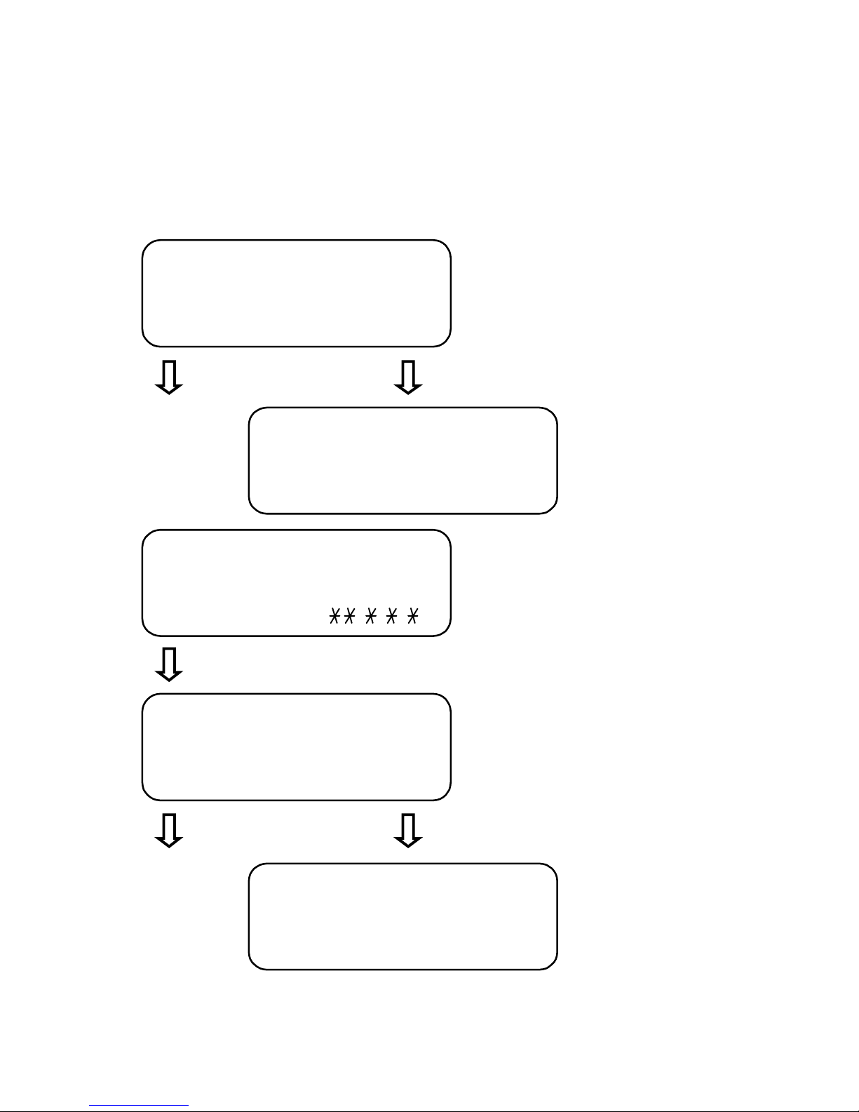
Data which can be displayed by pressing the DISPLAY key is as follows:
Default display - Energy
measured since the last reset.
Press DISPLAY Press ACCUM TOTAL
Accumulated Energy
Total (non-resettable).
Display segments test. Segments
are flashing.
Press DISPLAY
Volume of water measured through
the system since the last reset.
Press DISPLAY Press ACCUM TOTAL
Accumulated Volume
Total (non-resettable).
1 2 3 4 5 6 . 7
ENERGY KWH
7 8 9 1 0 1 . 8
ACCUM KWH
8 8 8 8.8.8.8
TEST 00.0.0.0.
1 4 3 4 . 6
VOLUME M3
6 4 3 2 6 . 5
ACCUM M3
Page 16
212-M-V2.1
14 Operation
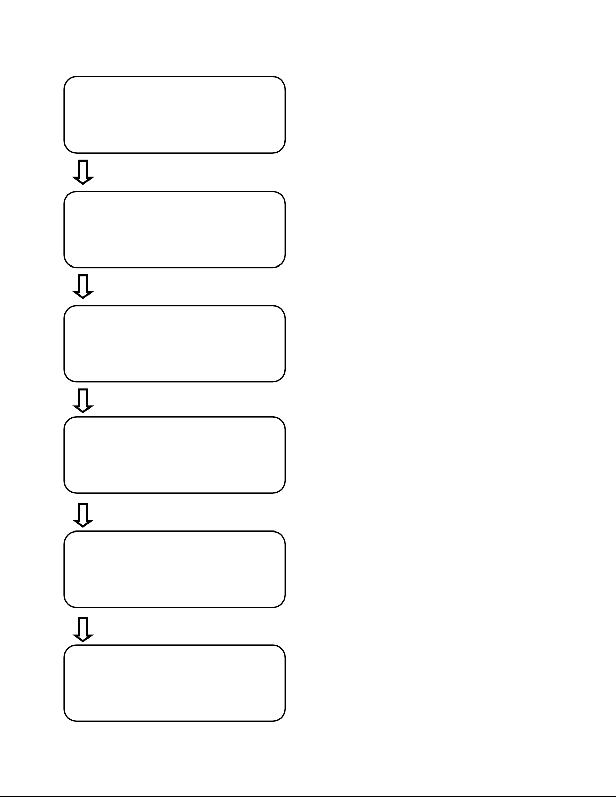
Energy flow rate.
Press DISPLAY
Volume flow rate.
Press DISPLAY
Temperature in the feed line.
Press DISPLAY
Temperature in the return line.
Press DISPLAY
Difference in temperature between the
feed and return lines.
Press DISPLAY
Peak power averaged over a 15 minute
period.
1 1 . 2
POWER KW
1 . 1 9 3
FLOW M3/H
8 0 . 6
FEED °c
7 2 . 3
RETURN °c
8 . 3
<
T K
1 1 . 6
PEAK P KW
Page 17
212-M-V2.1
Operation 15
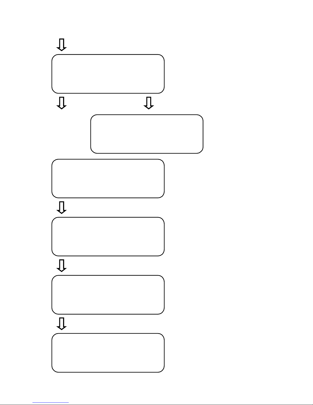
Press DISPLAY
Operating time elapsed since
the last reset.
Press DISPLAY Press ACCUM TOTAL
Accumulated operating
time (non-resettable).
Number of times the power has failed
or has been switched off to the unit
since the last reset.
Press DISPLAY
Time of day (24 hour clock).
Press DISPLAY
Date - Day - Month (SI Units)
Month - Day (US Units)
Press DISPLAY*
Time and date of the last logged
entry. Pressing the RESET key will
display the previous logged entries.
1 2 6 . 3 2
OP TM HR.MIN
1 2 6 4 3 . 3 2
ACCUM hr.min
6
supply fail
1 8-2 2
clock h-min
1 5 - 0 7
date 1998
1 4 2 3 . 0 7
tm log 1998
Page 18
212-M-V2.1
16 Operation
Press ACCUM TOTAL
Energy Total of selected
log entry.
* If logging is not used, pressing the DISPLAY key will return to the
Energy display.
1 2 6 4 3 . 3 2
en log kwh
Page 19
212-M-V2.1
Operation 17
3.1.2 Charge/Discharge Operation
If Charge/Discharge operation is programmed, the following display formats
will be apparent in place of the normal ENERGY display:
1 2 3 4 5 . 7
Charge Energy default display -
Charge Energy measured since
the last reset.
Press DISPLAY
Press ACCUM TOTAL
Accumulated Charge
Energy Total
(non-resettable).
Discharge Energy measured since
the last reset.
Press DISPLAY Press ACCUM TOTAL
Accumulated Discharge
Energy (non-resettable).
Press DISPLAY Press ACCUM TOTAL
Display segments test. Segments
are flashing.
Press DISPLAY
For continuation of displays refer to Section 3.1.1 Normal Operation.
EN chr KWH
7 8 9 1 0 1 . 8
ACCUM KWH
8 8 8 8.8.8.8
TEST 00.0.0.0.
1 4 3 4 . 6
en dis kwh
6 4 3 2 6 . 5
ACCUM kwh
Page 20
212-M-V2.1
18 Operation
3.1.3 Peak and Off-Peak Operation
If Peak and Off-Peak operation is programmed, the following display formats
will be apparent in place of the normal ENERGY display:
Peak Energy default display - Peak
Energy measured since the last reset.
Press DISPLAY Press ACCUM TOTAL
Accumulated Peak
Energy Total
(non-resettable).
Off-Peak Energy measured since the
last reset.
Press DISPLAY Press ACCUM TOTAL
Accumulated Off-Peak
Energy (non-resettable).
Display segments test. Segments are
flashing.
Press DISPLAY
For continuation of displays refer to Section 3.1.1 Normal Operation.
1 2 3 4 5 . 7
EN pk KWH
7 8 9 1 0 1 . 8
ACCUM KWH
8 8 8 8.8.8.8
TEST 00.0.0.0.
1 4 3 4 . 6
en opk kwh
6 4 3 2 6 . 5
ACCUM kwh
Page 21

212-M-V2.1
Operation 19
3.2 CHECKING SET-UP PARAMETERS
By pressing the DISPLAY key for 5 seconds, the program will enter the Check Setup Parameters mode. Various set-up parameters can be checked, but not
changed, by using the DISPLAY key.
Set-up Mode may be exited by either moving to the last set-up item, QUIT,
and selecting YES, or the DISPLAY key may be pressed and held for 5 seconds.
After this time, the Model 212 will return to normal operation.
The readout will display the following:
Parameter Value Description
1. LANG ENGL
GERM
Current language.
2. MODE HEAT
COOL
HT/CL
CHAR
Current mode of operation.
3. UNITS SI
US
Metric units.
US units.
4. FACTOR xxx.x p/ltr The K-factor of the flowmeter which
has been programmed.
5. CUTOFF x.xx Hz Low frequency cut-off of the
flowmeter expressed in Hz. The
Model 212 will not register flow if
the input frequency is below this
value. (Default is 0.25Hz).
See Section 3.4.
Page 22

212-M-V2.1
20 Operation
Parameter Value Description
6. OFFSET x.x
YES
0.0
NO
The offset between temperature sensors
(see Section 3.5).
The offset function is disabled.
7. FM LOC Feed
Ret
Location of the flowmeter in
either the feed or return line.
If High and Low alarms are installed:
8. REL0 Flw H
Flw L
Pwr H
Pwr L
∆t°H
∆t°L
Ft° H
Ft° L
Rt° H
Rt° L
Defines the parameter for Relay 0 output
as being high or low alarm for flow,
power, temperature difference, feed or
return temperatures.
9. REL0 xxxx.xxx Set point for parameters set in step
8 above. For low alarms the relay
will close
if the parameter is below the set point.
For high alarms it will close if the
parameter is above the set point.
10 REL1 ... Defines the parameter for Relay 1 as
in step 8 above.
11. REL1 xxxx.xxx Set point for parameter for Relay 1 as
in step 9 above.
Page 23

212-M-V2.1
Operation 21
Parameter Value Description
If 4-20mA Output is installed:
8. 4-20mA Flow
Pwr
∆t°
Ft°
Rt°
Defines the parameter to be output
as a 4-20mA signal.
9. 4mA xxxx.xxx Flowrate or temperature which
corresponds to 4mA.
10. 20mA xxxx.xxx Flowrate or temperature which
corresponds to 20mA.
12. PULSE Ener
Volu
Defines whether the pulse output is for
the energy or volume total.
13. PULSE xxx.x kWh Defines how often a pulse is
output.
14. PULSE 10 ms
20 ms
50 ms
100 ms
200 ms
500 ms
Defines the pulse width.
15. COMMS NONE
M-BUS
RS485
No Communications.
Meter-bus (see Section 4).
Modbus RTU.
16. BAUD xxxx
Communications baud rate between
300 and 9600.
Page 24

212-M-V2.1
22 Operation
Parameter Value Description
17. PARITY Even/Odd/None Communications parity.
18. BUS xx ADDR Bus address for the communications
link.
19. Df DIS YES
NO
Display will revert to Energy Total if no
key has been pressed for 10 seconds.
Display will stay on the last
displayed parameter.
20. Fr RES YES
NO
Enable RESET key on front panel.
Disable RESET key.
21. PK/OPK OFF
ON
Indicates whether Energy will be
totalised in separate Peak and Off-Peak
registers. (Only displayed if mode is set
to Heat, Cool or Heating/Cooling.)
22. PK ON xx
hour
Sets the hour at which energy
totalisation will commence in the PEAK
register. (Only displayed if mode is set
to Heat, Cool or Heating/Cooling and
PK/OPK is set to ON.)
23. PK OFF xx
hour
Sets the hour at which energy
totalisation will commence in the OFF
PEAK register. (Only displayed if mode
is set to Heat, Cool or Heating/Cooling
and PK/OPK is set to ON.)
24. LOG OFF
MONTH
WEEK
DAY
HOUR
Selects the interval at which Logging
will take place.
Page 25

212-M-V2.1
Operation 23
Parameter Value Description
25. RESOL NORM
HIGH
Display Energy, Volume and Temperatures with normal resolution.
Display Energy, Volume and Temperatures with high resolution for testing
purposes (EN1434-2). Energy and
Volume will be displayed as floating point
values in Joule and m
3
units respectively.
Temperatures will be displayed with two
decimal places.
26. S/WARE x.xx Software revision number.
27. QUIT YES
NO
Return to normal operation upon
pressing the DISPLAY key.
Continue in the Check Set-up mode.
To continue use the <key to select
NO and then press the DISPLAY key.
Page 26

212-M-V2.1
24 Operation
3.3 UNITS OF MEASUREMENT
The Model 212 can be programmed to operate in both metric and US units.
The units which are displayed are fully programmable during the Set-up
routine.
Metric
Energy kWh MWh MJ GJ Cal
KCal MCal
Power kW MW MJ/hour GJ/hour KCal/hour
MCal/hour
Volume litres m
3
Flow l/min m3/min m3/hour
Temperature °C
US Units
Energy kBTU ton x hour ton x day therm Cal
KCal MCal
Power KBTU/min KBTU/hour ton therm/min therm/hour
KCal/hour MCal/hour
Volume gallon ft
3
Flow gal/min ft3/min ft3/hour
Temperature °F
Note: Gallons are US Gallons.
Page 27

212-M-V2.1
Operation 25
3.4 FREQUENCY CUT-OFF
A frequency cut-off can be programmed to prevent registering very low
flow signals which may be the result of spurious pulses or a drift in the
zero point of a flowmeter, such as magnetic flowmeter.
Input frequencies at or below the cut-off are not registered and no flow is
totalised.
The relationship between the flow rate at cut-off and the frequency is:
where time base = 60 if the flow rate is in units/min and 3600
if the flow rate is in units/hour.
flow rate = flow rate at the cut-off.
K-factor = pulses per unit for the flowmeter.
For example, if the required cut-off is 50 l/h and the K-factor for the
flowmeter I 63, then the cut-off frequency:
= 0.88Hz
Generally, at frequencies above 0.25Hz, the cut-off is left at the default value
of 0.25Hz. However, some water meters produce relatively low frequencies
and the cut-off may need to be programmed to a frequency less than 0.25Hz.
Note: Be careful when setting low cut-off values below 0.25Hz, since the
display update time on the flow rate and power will become long. For
example, if the cut-off is set to 0.01Hz, the instrument will continue to display
the flow rate for 100 seconds, if the signal stops. This is because the time
interval between the signal at 0.01Hz is 100 seconds and the Model 212 must
wait this long before it can determine that the flow has actually stopped.
base
time
factor
-Kxrateflow
(Hz)frequency =
3600
63x50
f =
Page 28
212-M-V2.1
26 Operation
3.5 OFFSET FUNCTIONS
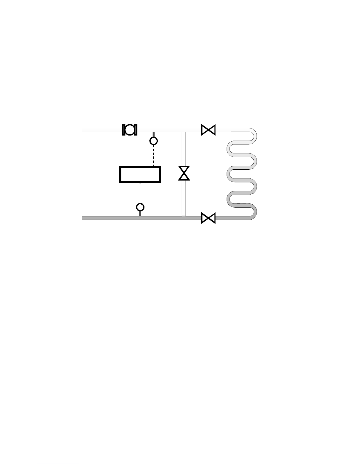
The offset function is designed for air conditioning systems with a very low
∆t.Often, in thesesystems,a bypass valve is installed to enable any
differences in the feed and return temperature to be zeroed out.
To compensate for any offset in the temperature sensors the Model 212 must
be put into the Set-up Program mode. The bypass valve "A" is then opened
and the valves "B" and "C" are closed.
With offset selected, the user then enters YES to zero the offset between the
feed and return lines. The measured offset will then be displayed on the
Model 212, the value of which will be stored when the Set-up Mode is exited.
The system is then returned to normal by closing valve "A" and opening valves
"B" and "C".
T
T
Flowmeter
Temperature
Sensor
Temperature
Sensor
212
LOAD
B
C
Feed Line
Return Line
Page 29

212-M-V2.1
Operation 27
3.6 OPERATING MODES
The Model 212 may be programmed to operate in either of four modes, as
follows:
1. Heating
2. Cooling
3. Heating/Cooling
4. Charge/Discharge
3.6.1 Heating
Heating mode is used when the application is for Heating only and assumes that
the Feed Temperature will always be higher than the Return Temperature
(positive∆t).
If theFeedTemperatureislowerthantheReturnTemperature(negative ∆t),
then no Energy is totalised, but Volumetric Flow is still totalised.
3.6.2 Cooling
Cooling mode is used when the application is for Cooling only and assumes
that the Feed Temperature will always be lower than the Return Temperature
(negative∆t). IftheFeedTemperatureishigherthantheReturnTemperature
(positive∆t),thennoEnergyistotalised,but Volumetric Flowisstilltotalised.
3.6.3 Heating/Cooling
Heating/Cooling mode is used where the flow of Energy may be for Heating
orCooling. In this mode Energyis increased regardless of whether ∆t is
positive or negative.
3.6.4 Charge/Discharge
Charge/Discharge mode is used when it is necessary to maintain two Energy
totals.
Oneforwhen ∆tispositive andoneforwhen∆tisnegative. Onlyonetotal
at a time is used.
Page 30

212-M-V2.1
28 Operation
3.7 PEAK AND OFF-PEAK
When the Model 212 is programmed for either Heating, Cooling or Heating
and Cooling, it is possible to program Peak and Off-Peak times. This enables
the Model 212 to record Energy totals in two separate registers, depending
on the time of day.
A 24 hour period can be programmed as having one peak period and one off-
peak period. For example, if "PEAK ON" is programmed as 09 and "PEAK OFF"
is programmed as 18, then between 9.00am and 6.00pm totalisation would
occur in the Peak register and between 6.00pm and 9.00am, totalisation would
occur in the Off-Peak register.
Page 31

212-M-V2.1
Operation 29
3.8 LOGGING
The Model 212 has the facility to log the current Energy total at fixed
intervals which can be programmed to hour, day, week or month.
HOUR A log entry will occur at 00 minutes each hour.
DAY A log entry will occur at 00 hours 00 minutes each day.
WEEK A log entry will occur at 00 hours 00 minutes each Monday.
MONTH A log entry will occur at 00 hours 00 minutes on the 1st of the
month.
A total of 31 log entries can be stored and viewed by the Model 212.
After 31 entries have been completed, the oldest logged entry is overwritten
by the newest logged entry, therefore only the 31 most current logged entries
are kept.
Logging facilities are only available if the mode of operation is set to
Heating, Cooling or Heating/Cooling without Peak/Off-Peak Energy registers.
Page 32
212-M-V2.1
30 Communications
4. COMMUNICATIONS
Three modes of communications are provided:
1. Meter-bus.
2. Infra-red Communications link using M-Bus protocol.
3. RS485 with Modbus RTU protocol.
Terminals 24 and 25 provide a connection for both the Meter-bus and the
RS485.
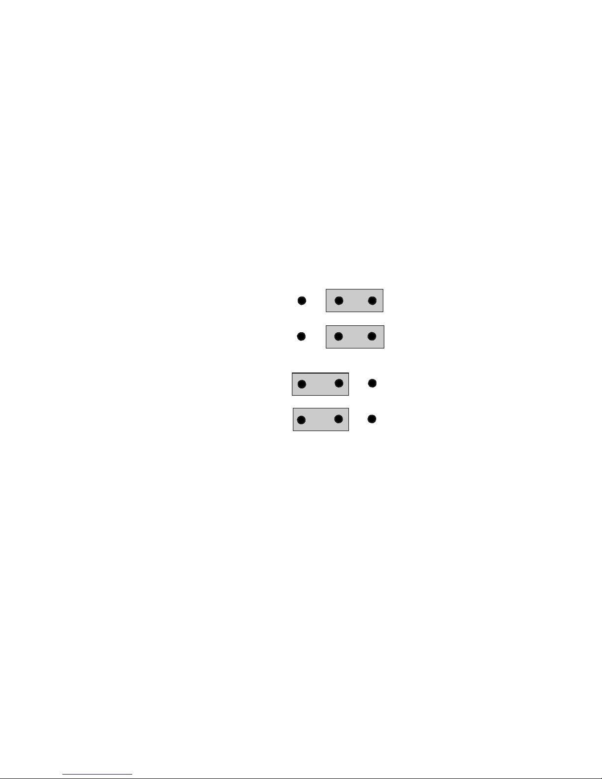
Links on the main board determine which interface is selected as follows:
These links are accessible by removing the front panel as detailed in section 7.2
and the link positions are as shown in the drawing in section 7.3. Links are
made via small black caps which fit over the connecting posts, thereby creating
a link.
B A
Meter-bus
Link 4
Link 5
RS485
Link 4
Link 5
Page 33

212-M-V2.1
Communications 31
4.1 METER-BUS
The Model 212 serves as a secondary station in communications and includes
the Meter-bus hardware and protocol according to IEC 870-5 and as detailed
in EN 1434-3 with variable data format for reading out all parameters.
Hardware
The Meter-bus connection is available through galvanically isolated
terminals 24/25 (irrespective of polarity) or optical interface (optional).
The levels of input voltage/output current are as detailed in EN 1434-3.
Bus Address
The bus address of the Model 212 is programmable in range between 0 to
250.
Some addresses are reserved according to EN 1434-3 and have a special
meaning:
0 default address for unconfigured meter
251...253 reserved
254 answer regardless of own address
255 broadcast, no response
Protocol
The protocol uses asynchronous serial bit transmission in half-duplex mode
with 1 start bit, 8 data bits, 1 even parity bit, 1 stop bit and programmable
baud rate (300 to 9600 baud). Link service classes S2 (SEND/CONFIRM) and S3
(REQUEST/RESPOND) are provided utilising frame format class FT1.2 according
to IEC 870-5.
This protocol incorporates a frame counter bit (FCB) which has to be toggled
by primary station if the last communication was undisturbed. The Model
212 keeps a copy of the last transmitted CONFIRM or RESPOND frame in
order to retransmit it if the next FCB has not been toggled.
Page 34

212-M-V2.1
32 Communications
Reception Frames*
SEND (normalise):
10 40 ADR CS 16
REQUEST (data):
10 5B/7B ADR CS 16
SEND (data):
68 LEN LEN 68 53/73 ADR 51/55 DATA... CS 16
Transmission Frames*
CONFIRM (acknowledgment of NORMALISE):
E5
CONFIRM (acknowledgment):
10 00 ADR CS 16
CONFIRM (no acknowledgment, link busy):
10 01 ADR CS 16
RESPOND (no acknowledgment, data is not available):
10 09 ADR CS 16
RESPOND (data)
68 LEN LEN 68 08 ADR 72 DATA... CS 16
* byte values are represented in the hexadecimal format.
Page 35

212-M-V2.1
Communications 33
4.2 INFRA-RED COMMUNICATIONS LINK
The infra-red communication option uses the Meter-bus protocol as
defined in IEC 870-5 and as detailed in EN 1434-3.
This function is not implemented at this time.
Page 36

212-M-V2.1
34 Communications
4.3 RS485 WITH MODBUS RTU PROTOCOL
Modbus RTU is an industry standard protocol which allows the Model 212 to
be easily interfaced to DCS or PLC, or to computers running supervisor
software systems.
The Model 212 serves as a slave station in communications and includes the
RS485 hardware and implementation of the standard protocol according to
Modicon Modbus Protocol (RTU-mode) and as detailed in PI-MBUS-300 Rev F.
Implementation specific details are as follows.
4.3.1 Hardware
The Modbus connection is available on terminals 24/25 and links 4 and 5 must
be connected as described at the beginning of this chapter.
4.3.2 Protocol
The protocol uses asynchronous serial bit transmission in half duplex mode
with 1 start bit, 8 data bits and (1 parity bit + 1 stop bit) or 2 stop bits
depending on whether the parity check has been programmed to "NONE" or
not. The baud rate is programmable in range from 300 to 9600 Baud. The
parity check can be programmed to Even, Odd or None. Link service classes
SEND/CONFIRM and REQUEST/RESPOND are provided utilising frame formats
according to PI-MBUS-300.
In RTU mode, messages start with a silent interval of at least 3.5 character
time.
Following the last transmitted character, a similar interval of at least 3.5
character times marks the end of the message. A new message can begin
after this interval.
The entire message frame must be transmitted as a continuous stream. A
typical message frame is shown below:
ADDRESS FUNCTION DATA CRC CHECK
1 byte 1 byte N bytes 2 bytes
Page 37

212-M-V2.1
Communications 35
Except for broadcast messages, when a master device sends a query to a
slave device it expects a normal response. One of four possible events can
occur from the master's query:
1. If the slave device receives the query without a communication
error, and can handle the query normally, it returns a normal
response.
2. If the slave does not receive the query due to a communication
error, no response is returned. The master program has to
process a timeout condition for the query.
3. If the slave receives the query, but detects a communications
error (parity or CRC), no response is returned. The master
program has to process a timeout condition for the query.
4. If the slave receives the query without a communication error,
but cannot handle it (for example, if the request is to read a
nonexistent register), the slave will return an exception
response informing the master of the nature of the error.
4.3.3 Bus Address
The bus address of the Model 212 is programmable in range between 1 to
247.
Some addresses are reserved according to PI-MBUS-300 and have a
special meaning:
0 Broadcast, no response
247...255 Reserved
Page 38

212-M-V2.1
36 Communications
4.3.4 Function Codes
The Model 212 accepts the following function codes:
Code Name Description
03 Read data register(s) Obtain the content of one or more 2
byte data registers.
06 Preset data register Preset one 2 byte data register.
07 Read status register Obtain the content of 1 byte status register.
16 Preset data register(s) Preset one or more 2 byte data registers.
4.3.5 Exception Response
The Model 212 forms an exception response by adding 80H to the function
code and using an exception code as the 1 byte data field in the returned
frame.
Implemented exception codes are as follows:
Code Name Description
01 Illegal function The function code is not a legal action for
the slave.
02 Illegal data address The data address is not a legal address
for the slave.
03 Illegal data value The data value is not a legal value for the
slave.
05 Acknowledge The slave has accepted the request and
is
processing it, but a long duration of time
will be required to do so.
06 Slave device busy The slave is engaged in processing a long
duration program command. The
mastershould re-transmit the message
later when the slave is free.
Page 39

212-M-V2.1
Communications 37
4.3.6 List of Data Registers
The following list describes data registers for the Model 212. Engineering
units programmed during setup are used for floating point values.
Conventional numbering of registers start from 1, therefore be aware that
"register 1" in this case has an "address 0" (low level framing) and so on.
Read and Write Registers
Register Name Value Note
01 Heating mode 00 - heat
01 - cool
02 - heat/cool
03 - charge/discharge
02 Total reset 00 - no action
01 - reset totals
03 Flowmeter location 00 - feed line
01 - return line
If High and Low Alarms are installed:
04 Relay 0 mode 00 - flow high
01 - flow low
02 - power high
03 - power low
04‐∆t°high
05‐∆t°low
06 - feed t° high
07 - feed t° low
08 - return t° high
09 - return t° low
Page 40

212-M-V2.1
38 Communications
Register Name Value Note
05 Relay 1 mode 00 - flow high
01 - flow low
02 - power high
03 - power low
04‐∆t°high
05‐∆t°low
06 - feed t° high
07 - feed t° low
08 - return t° high
09 - return t° low
If 4-20mA Output is installed:
04 4-20mA mode 00 - flow
01 - power
02‐∆t°
03 - feed t°
04 - return t°
06 Pulse out mode 00 - volume
01 - energy
07 Year 00...99 (when writing)
08 Month 01...12
09 Day 01...31
10 Hour 00...23
11 Minute 00...59
12 Peak mode 00 - off
01 - on
13 Peak on setpoint 00...23
14 Peak off setpoint 00...23
15 Logging mode 00 - off
01 - month
02 - week
03 - day
04 - hour
Page 41

212-M-V2.1
Communications 39
Register Name Value Note
16 K-factor 0.001...999,999.9 FP
18 Cutoff frequency 0.01...0.99 FP
If High and Low Alarms are installed:
20 Relay 0 setpoint 0.000...999,999.9 FP
22 Relay 1 setpoint 0.000...999,999.9 FP
If 4-20mA Output is installed:
20 4mA setpoint 0.000...999,999.9 FP
22 20mA setpoint 0.000...999,999.9 FP
24 Pulse out setpoint 0.000...999,999.9 FP
Read Only Registers
Register Name Value Note
26 Energy 0 FP
28 Energy 1 FP
30 Accumulated energy 0 FP
32 Accumulated energy 1 FP
34 Volume FP
36 Accumulated volume FP
38 Not Used FP
40 Not Used FP
42 Elapsed time FP
44 Accumulated elapsed time FP
46 Power FP
48 Peak power FP
50 Volume flow FP
52 Not Used FP
54 Flow temperature FP
56 Return temperature FP
58 Temperature difference FP
60 Supply failures
61 Exception register 00 - no failure
01 - RTD failure
Page 42

212-M-V2.1
40 Communications
Register Name Value Note
62 Logging point 1 - energy FP
64 Logging point 1 - time (seconds) since 01.01.1996 LI
...
...
...
182 Logging point 31 - energy FP
184 Logging point 31 - time (seconds) since 01.01.1996 LI
186 K-factor unit SI: 00 - pulse/ltr
01 - pulse/m
3
US: 00 - pulse/gallon
01 - pulse/ft
3
187 Energy unit SI: 00 - MJ
01 - GJ
02 - kWh
03 - MWh
04 - Cal
05 - KCal
06 - MCal
US: 00 - kBTU
01 - ton x hour
02 - ton x day
03 - therm
04 - Cal
05 - KCal
06 - MCal
188 Volume unit SI: 00 - ltr
01 - m
3
US: 00 - gallon
01 - ft
3
189 Power unit SI: 00 - MJ/hour
01 - GJ/hour
02 - kW
03 - MW
04 - KCal/hour
05 - MCal/hour
Page 43

212-M-V2.1
Communications 41
Register Name Value Note
US: 00 - kBTU/min
01 - kBTU/hour
02 - ton
03 - therm/min
04 - therm/hour
05 - KCal/hour
06 - MCal/hour
190 Volume flow unit SI: 00 - ltr/min
01 - m
3
/min
02 - m3/hour
US: 00 - gallon/min
01 - ft3/min
02 - ft3/hour
Notes:
FP This variable is represented in IEEE-754 Floating Point 4 byte
format and requires two 2 byte data registers used as Modicon's
floats:
IEEE-754 Modicon Registers
1st byte low byte (register X)
2nd byte high byte (register X)
3rd byte low byte (register X+1)
4th byte high byte (register X+1)
This means that two data registers must be read/written
to obtain/preset one data value.
LI This variable is represented as a long integer in 4 byte format
and requires two 2 byte data registers:
Long Integer Modicon Registers
1st byte (MSB) high byte (register X)
2nd byte low byte (register X)
3rd byte high byte (register X+1)
4th byte (LSB) low byte (register X+1)
This means that two data registers must be read/written
to obtain/preset one data value.
Page 44

212-M-V2.1
42 Set-up Mode
5. SET-UP MODE
The Set-up Mode can only be entered by removing the lower cover strip
(see Section 7). Usually this will mean breaking a seal which prevents the
strip being removed without tampering.
Once the strip is removed, a small hole provides access to a pushbutton.
By inserting a pen tip or similar item into the hole and pressing the
pushbutton, the
instrument will enter the Set-up mode whereby the parameters can be
entered or changed.
The DISPLAY key is used to step through each parameter and the < and û keys
are used to step through and change items (digits, decimal points or units).
The item which can be changed flashes. Thus the instrument can be fully
programmed on-site without having to purchase a separate programmer.
If the Set-up access pushbutton is pressed while the Model 212 is in Set-up
Mode, the display will return to step 1.
Set-up Mode may be exited by either moving to the last set-up item, QUIT,
and selecting YES, or the DISPLAY key may be pressed and held for 5 seconds.
After this time, the Model 212 will return to normal operation.
Parameter Value Description
1. LANG ENGL
GERM
Select language.
2. MODE HEAT
COOL
HT/CL
CHAR
Selects the mode of operation
between Heating, Cooling, Heating and
Cooling or Charge/Discharge.
3. RESET NO
YES Resets totals upon exiting the Set-up
Mode.
Page 45

212-M-V2.1
Set-up Mode 43
Parameter Value Description
4. UNITS SI
US
Metric units.
US units.
5. ENERGY Set energy units for display.
6. VOLUM Set volume units for display.
7. POWER Set power units for display.
8. FLOW Set flow rate units for display.
9. FACTOR xxx.x p/ltr The K-factor of the flowmeter which
has been programmed.
(See flowmeter manufacturer's data.)
10. CUTOFF x.xx Hz Low frequency cut-off of the flowmeter,
expressed in Hz. The Model 212 will not
register flow if the input frequency is
below this value. Note that the default is
0.25Hz and it is recommended to not
change this value unless the flowmeter
produces very low frequencies.
(See Section 3.4.)
11. OFFSET x.x
YES
0.0
NO
The offset between temperature
sensors.
(See Section 3.5).
The offset function is disabled.
12. FM LOC Feed
Ret
Location of the flowmeter as being
in either the feed or return line.
Page 46

212-M-V2.1
44 Set-up Mode
Parameter Value Description
If High and Low alarms are installed:
13. REL0 Flw H
Flw L
Pwr H
Pwr L
∆t°H
∆t°L
Ft° H
Ft° L
Rt° H
Rt° L
Defines the parameter for Relay 0
output as being high or low alarm for
flow, power, temperature difference,
feed or return temperatures.
14. REL0 xxxx.xxx Set point for parameters set in step
13 above. For low alarms the relay
will close if the parameter is below
the set point.
For high alarms it will close if the
parameter is above the set point.
15. REL1 ... Defines the parameter for Relay 1 as
in step 13 above.
16. REL1 xxxx.xxx Set point for parameter for Relay 1 as
in step 14 above.
If 4-20mA Output is installed:
13. 4-20mA Flow
Pwr
∆t°
Ft°
Rt°
Defines the parameter to be output
as a
4-20mA signal.
14. 4mA xxxx.xxx Flowrate or temperature which
corresponds to 4mA.
Page 47

212-M-V2.1
Set-up Mode 45
Parameter Value Description
15. 20mA xxxx.xxx Flowrate or temperature which
corresponds to 20mA.
17. PULSE Ener
Volu
Defines whether the pulse output is for
the
energy or volume total.
18. PULSE xxx.x kWh Defines how often a pulse is output.
19. PULSE 10 ms
20 ms
50 ms
100 ms
200 ms
500 ms
Defines the pulse width.
20. CLOCK xx
Hour/Min
Set time in hours and minutes.
Real time clock is able to run
without power for two days typically.
21. DATE xxxx
Year/Month/
Day
Set date in year, month and day.
Real time clock is able to run
without power for two days typically.
22. COMMS NONE
M-BUS
RS485
If no communications are to be used,
Set-up Mode continues at step 25.
Meter-bus (see Section 4).
Modbus RTU.
23. BAUD xxxx Communications baud rate between
300 and 9600.
24. PARITY Even/Odd/None Communications parity (with Meter bus the parity is not changeable and is
set to even parity).
Page 48

212-M-V2.1
46 Input & Output Connections
Parameter Value Description
25. BUS xx ADDR Bus address for the communications
link.
NO
Display will revert to Energy Total if no
key has been pressed for 10 seconds.
Display will stay on the last
displayed parameter.
27. Fr RES YES
NO
Enable RESET key on front panel.
Disable RESET key.
28. PK/OPK OFF
ON
Selects whether Energy will be totalised
in separate Peak and Off-Peak registers.
If set to OFF, Set-up continues at step 30.
29. PK ON xx
hour
Sets the hour at which energy
totalisation will commence in the PEAK
register.
(Only available if mode is set to Heat,
Cool or Heating/Cooling.)
30. PK OFF xx
hour
Sets the hour at which energy
totalisation will commence in the OFF
PEAK register.
(Only available if mode is set to Heat,
Cool or Heating/Cooling.)
31. LOG OFF
MONTH
WEEK
DAY
HOUR
Selects the interval at which Logging
will take place.
Logging is only available if the mode
(step 2) is set to Heating, Cooling or
Heating/Cooling and the Peak/OffPeak (step 27) is set to OFF. If
logging is not available, this step
will not be displayed.
Page 49

212-M-V2.1
Set-up Mode 47
Parameter Value Description
32. RESOL NORM
HIGH
Display Energy, Volume and Temperatures with normal resolution.
Display energy, Volume and Temperatures with high resolution for testing
purposes (EN1434-2). Energy and
Volume will be displayed as floating
point values in Joule and m
3
units
respectively.
Temperatures will be displayed with two
decimal places.
33. QUIT YES
NO
Return to normal operation upon
pressing the DISPLAY key.
Continue in the Set-up mode. To
continue use the < key to select NO and
then press the DISPLAY key.
Page 50

212-M-V2.1
48 Input & Output Connections
6. INPUT & OUTPUT
CONNECTIONS
6.1 FLOWMETER INPUT
The instrument will accept frequency or pulse inputs from a wide range
of flowmeters.
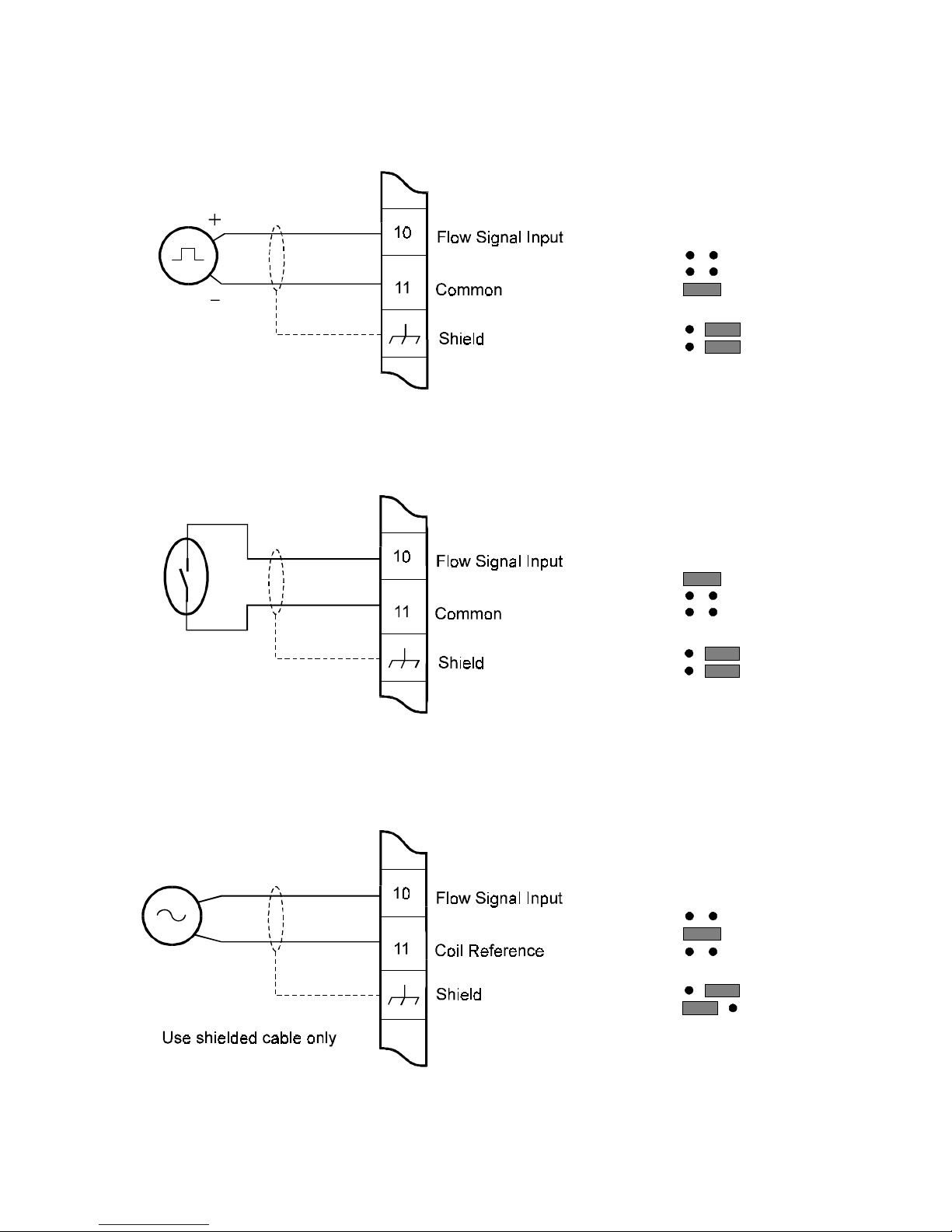
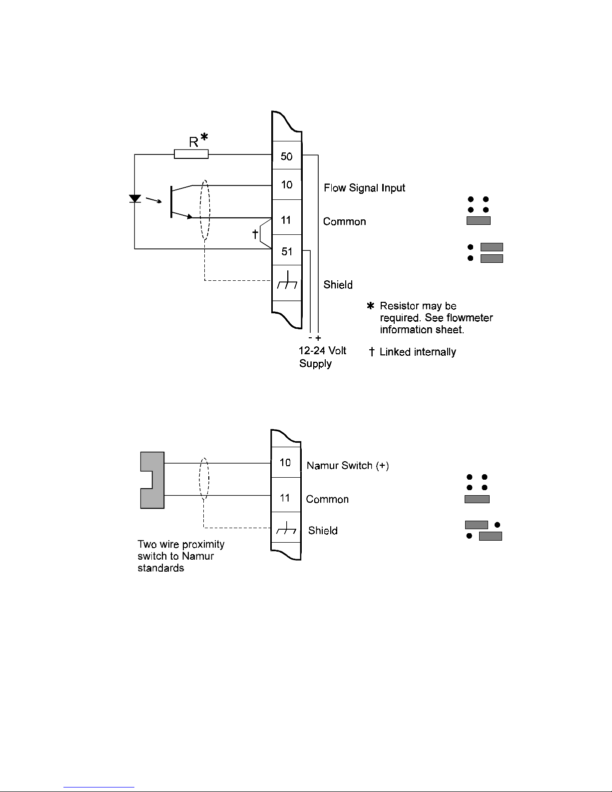
Examples of connection diagrams are shown on the following pages.
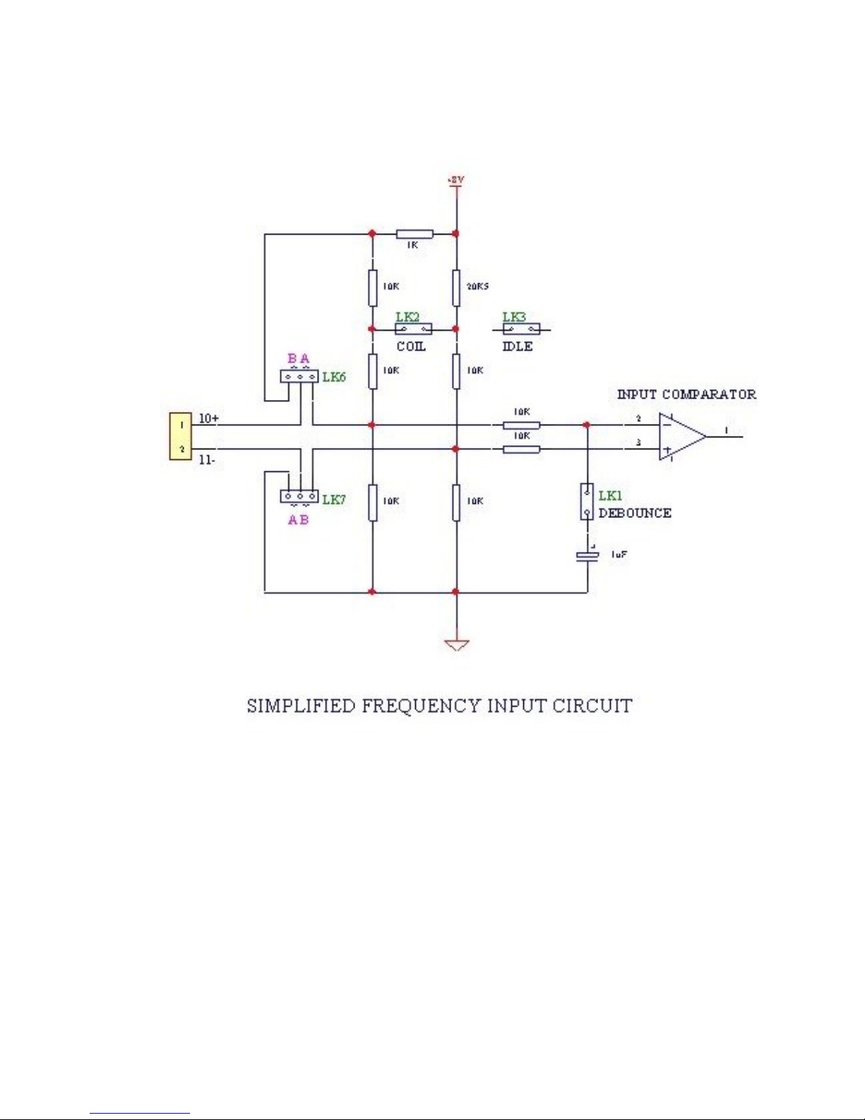
Note that it may be necessary to change the position of the links as shown.
These links are accessible by removing the front panel as detailed in section
7.2 and the link positions are shown in the drawing in section 7.3.
Link 1 Links in an input filter for a reed switch. The
maximum input frequency is approximately 500Hz
with this filter.
Link 2 Link for coils (eg. turbine or paddlewheel flow sensors).
Link 3 Not connected. This position is selected if links 1 or
2 are not required.
Link 6 Selects a two wire proximity switch when in position B.
Link 7 Selects a coil input when in position B.
The links are made via small black caps which fit over the two connecting
posts thereby creating the link.
The input on terminals 10 or 11 is limited to 30 volts maximum.
Note: After connecting the flowmeter, it is also necessary to program
the flowmeter factor. This is supplied by the flowmeter manufacturer
and represents the number of pulses per litre, m3, gallon or ft3 that
the flowmeter outputs for each unit of volume. It is often referred to
as the K-factor.
Page 51
212-M-V2.1
Input & Output Connections 49
Page 52
212-M-V2.1
50 Input & Output Connections
1. Pulse
2. Reed Switch
3. Coils eg. mV signals from turbine flowmeters or
Links
B A
LK1
LK2
LK3
LK6
LK7
LK1
LK2
LK3
LK6
LK7
LK1
LK2
LK3
LK6
LK7
B A
B A
Links
Links
Page 53
212-M-V2.1
Input & Output Connections 51
4. Opto-Sensors
5. Namur Switch
LK1
LK2
LK3
LK6
LK7
B A
Links
Links
B A
LK1
LK2
LK3
LK6
LK7
Page 54
212-M-V2.1
52 Input & Output Connections
6.2 RTD INPUT
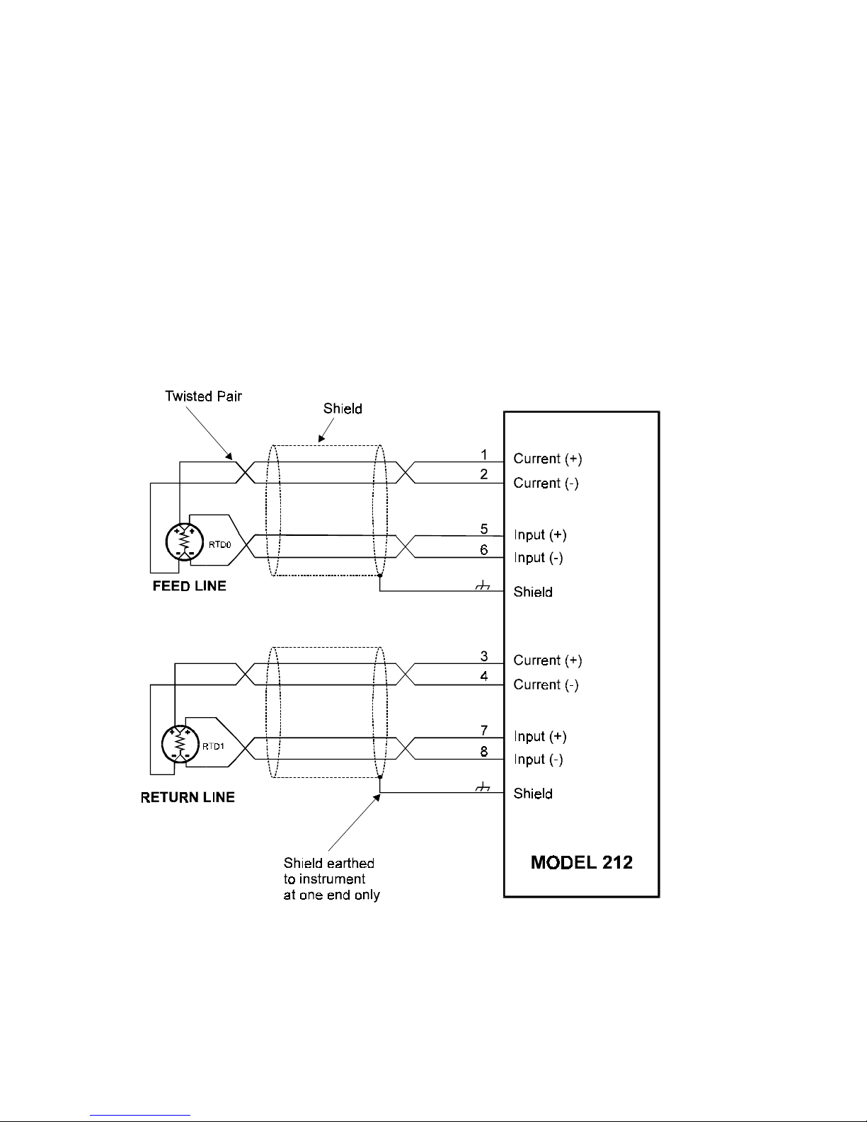
The Model 212 uses four wire RTDs to provide optimum accuracy and stability.
The RTDs are high grade 100 ohm platinum types manufactured to
BS1094 standards. For maximum accuracy, RTDs should be a matched
pair, Class A to IEC 751 standard.
It is not necessary with four wire RTDs to have equal lead lengths, but
cables should not be longer than 50 meters (150 feet). They should be
shielded twisted pairs connected as follows:
Note: Care must be taken to ensure the (+) of the current terminal is
connected to the same side of the RTD as the (+) of the input terminal. The
RTD, itself, has no polarity.
Page 55
212-M-V2.1
Input & Output Connections 53
6.3 POWER SUPPLY
The Model 212 will operate from a central 12-24 Volts dc source and
typically draws around 60mA.
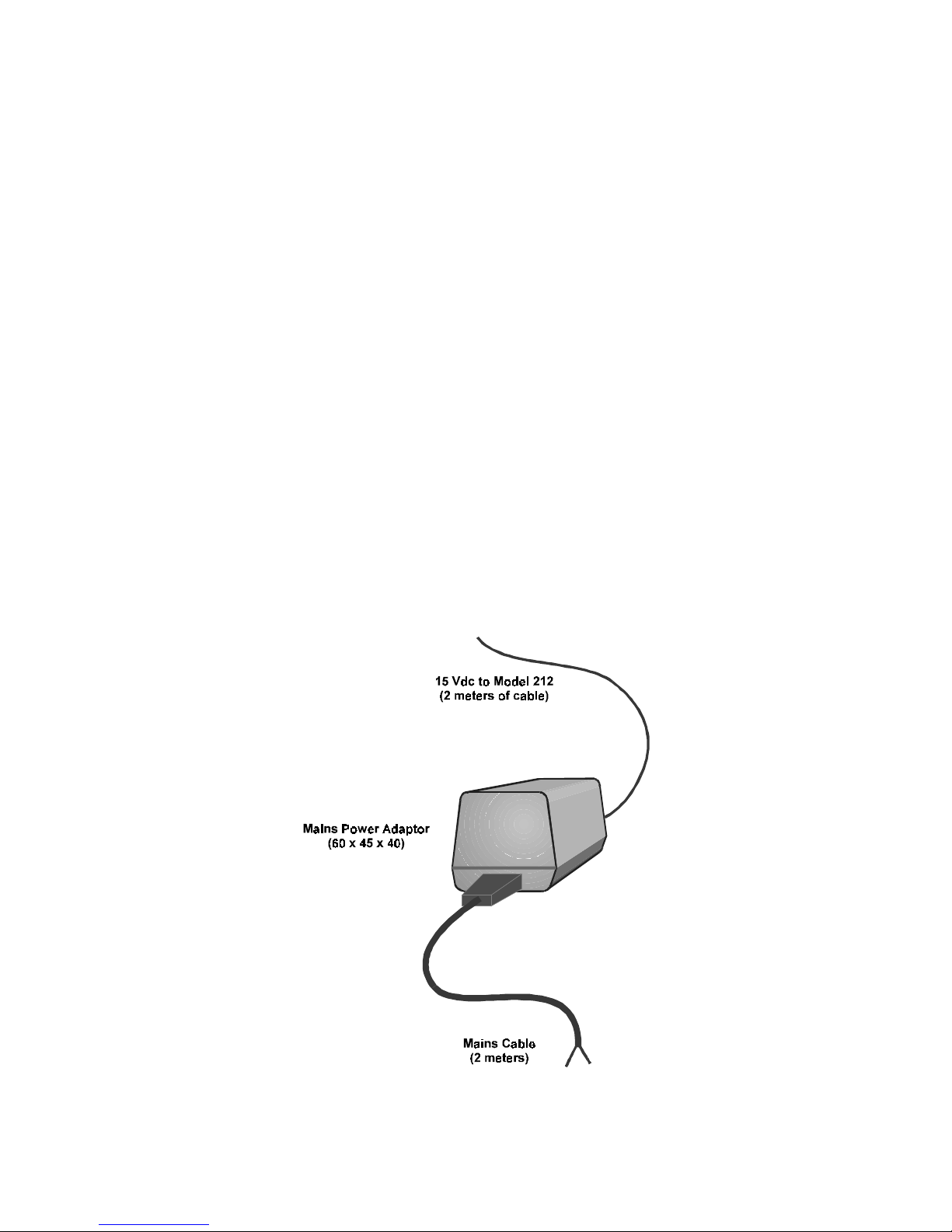
A power adapter is supplied as standard and this supply can also be used to
power the flowmeter, alarms and peripheral items.
The flexible power supply system allows:
1. The Model 212 to be operated from a low cost power adapter.
2. Multiple units to be powered from a single power source.
3. Mains powered systems with battery backup to be
easily implemented using standard sealed lead acid
batteries.
By separating the ac power from the main Model 212, the system is
completely safe to install and reduces the need for qualified electricians to
complete the wiring.
Page 56
212-M-V2.1
54 Input & Output Connections
6.4 PULSE OUTPUT
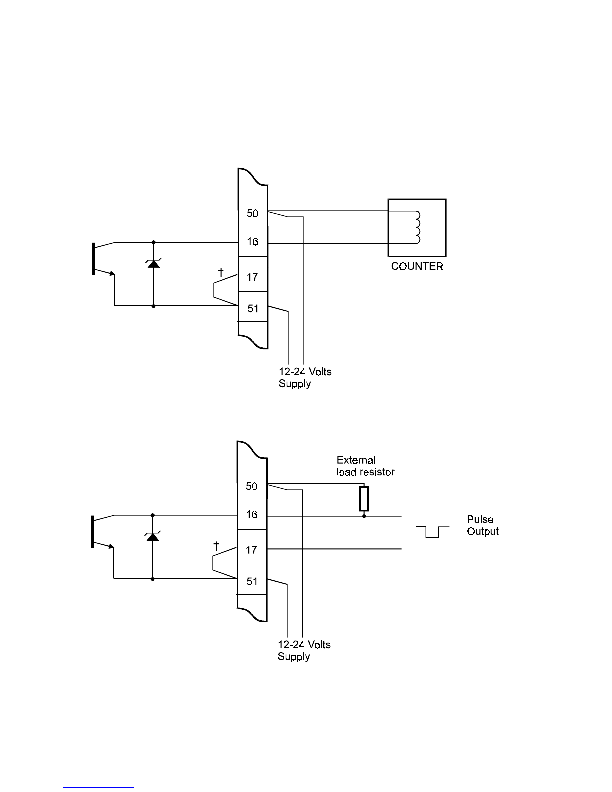
A pulse output is available on terminals 16 and 17. The output is an open
collector transistor suitable for external counters.
Linked internally
Page 57

212-M-V2.1
Input & Output Connections 55
The output on terminal 16 is capable of sinking up to 100mA maximum and
can withstand external voltages of 30 Volts. Reverse polarity and inductive
load protection is provided.
Two connection examples are provided. If a voltage pulse output is required,
an external load resistor must be used as shown on the second diagram.
The pulse output can be programmed during Set-up as an energy or
volumetric flow output. The pulse rate is also programmable, so that a
pulse can, for example, be programmed to occur every .001m
3
.
Hence, in the above example, if the volumetric flow rate was 60m3/hour, then
this is equivalent to 0.0167m3/sec. If a pulse occurs every 0.001m3 then the
output frequency would be 16.7Hz.
Duration of the pulse is programmable as 10, 20, 50, 100, 200 or 500ms
and determines the maximum pulse output frequency:
Hz
Width in ms)x pulse(2
1000
Page 58
212-M-V2.1
56 Input & Output Connections
6.5 ALARM RELAY OUTPUTS
Note that the High/Low alarms are not available when the 4-20mA output
option is installed.
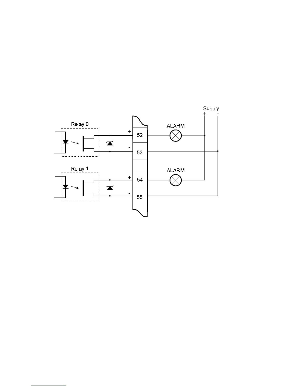
Two Solid State dc relays are provided as alarm outputs. These relays are
fully isolated and can be used to drive external relays, lamps, audible alarms,
etc.
Output characteristics for Relay 0 and Relay 1 are:
Maximum Voltage 30 Volts dc
Maximum Current 250mA dc
Off State Leakage Current 5uA maximum
On State Resistance 6 ohms maximum
The relays can be individually programmed during Set-up to alarm
on:
Flow rate Low or High
Power Low or High
Feed Temperature Low or High
Return Temperature Low or High
Temperature Difference Low or High
Page 59

212-M-V2.1
Input & Output Connections 57
For example, Relay 0 can be programmed to alarm if the flow rate is below
a certain value, while Relay 1 can be programmed to alarm if the power
consumption exceeds a preset value.
In the alarm condition the relays are closed, and are open in the nonalarm condition or when the instrument is unpowered.
Page 60
212-M-V2.1
58 Input & Output Connections
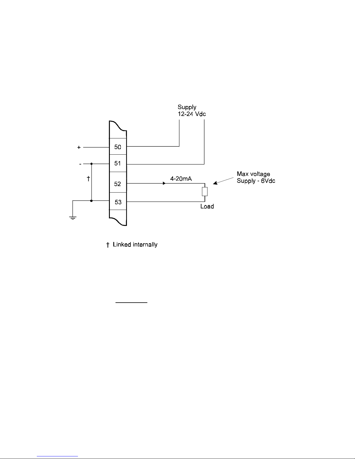
6.6 4-20mA OUTPUT OPTION
A 4-20mA Output Option is available and can be used to retransmit the
volumetric flowrate, energy flowrate, temperature difference, feed
temperature and return temperature.
The maximum output voltage is the supply voltage less 6 volts. Therefore
the maximum load resistance can be calculated as:
At 24 volts, Rmax = 900 ohms and at 12 volts, Rmax = 300 ohms.
0.02
6-Supply
Maximum Load =
Page 61

212-M-V2.1
Input & Output Connections 59
The output specifications are:
Current Range: 2.0mA to 22.0mA.
Linearity & Resolution: 0.02% of span.
Accuracy: 0.1% of span.
Response Time: 0.5 seconds to 99% of step.
The output can be programmed to output the following:
Volumetric Flowrate
Energy Flowrate (power)
Feed Temperature
Return Temperature
Temperature Difference
The 4mA point and 20mA point can be individually programmed during
setup.
Page 62
212-M-V2.1
Installation 60
7. INSTALLATION
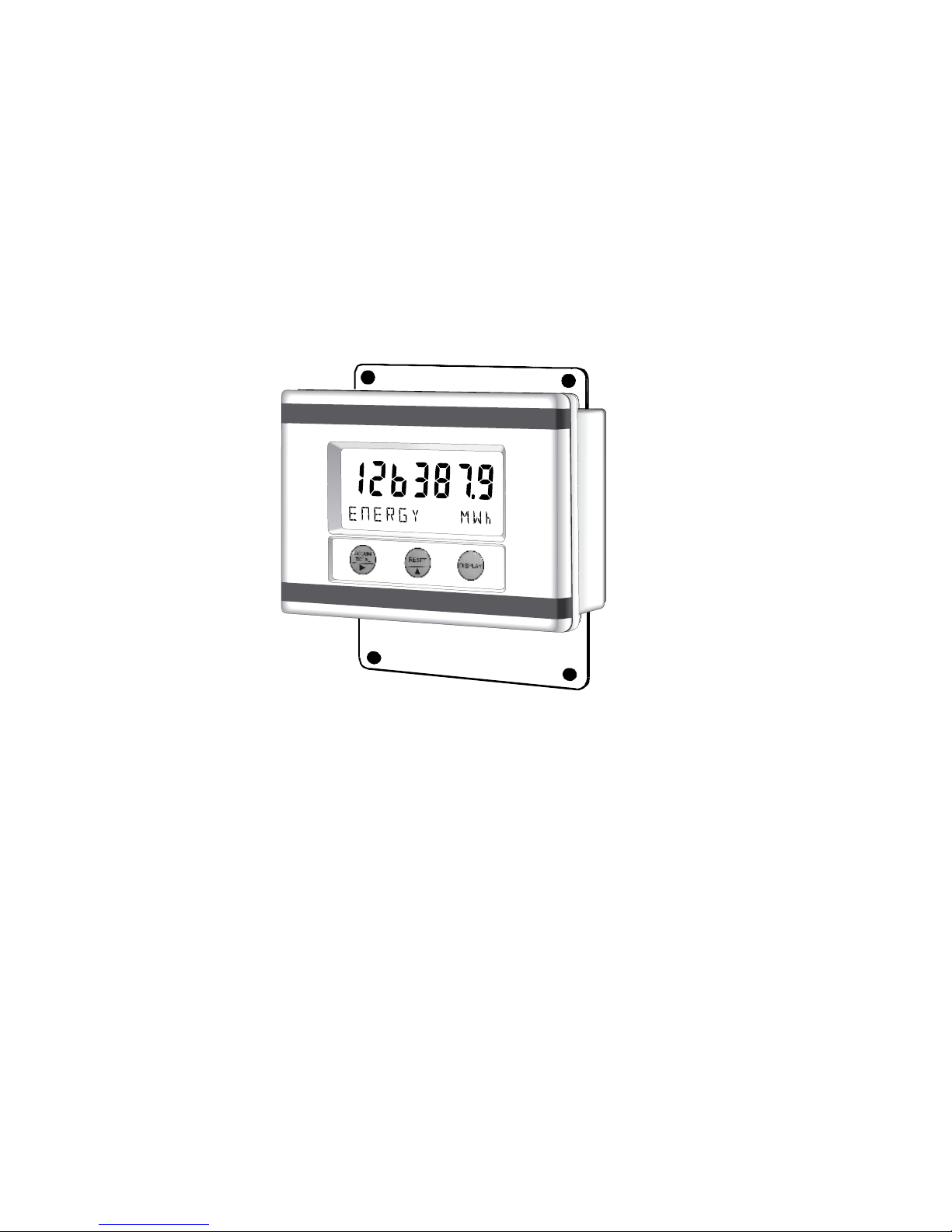
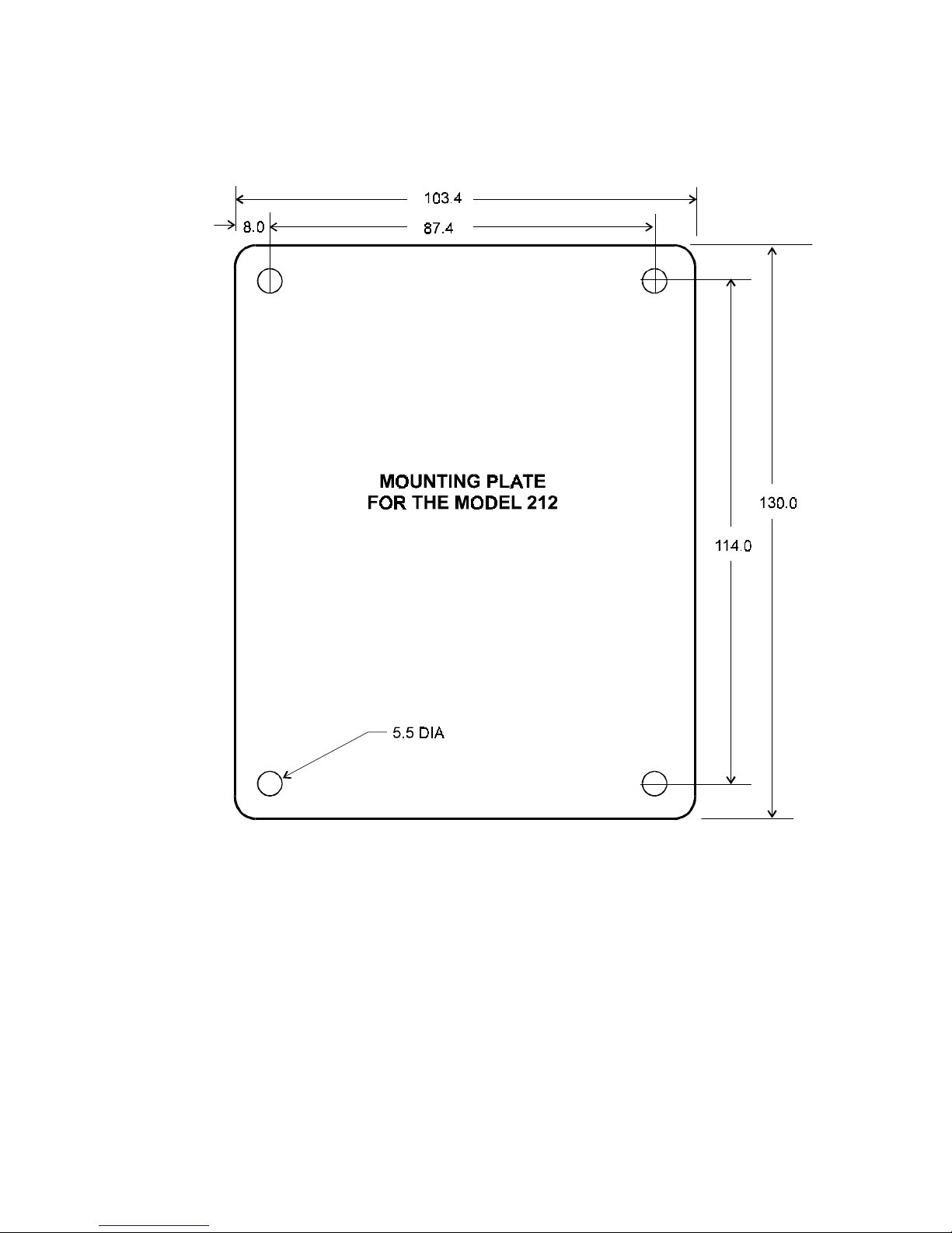
7.1 WALL MOUNTING
A wall mounting bracket is supplied with each instrument. A drilling diagram
is outlined on the following page.
Page 63
212-M-V2.1
Installation 61
Page 64
212-M-V2.1
62 Installation
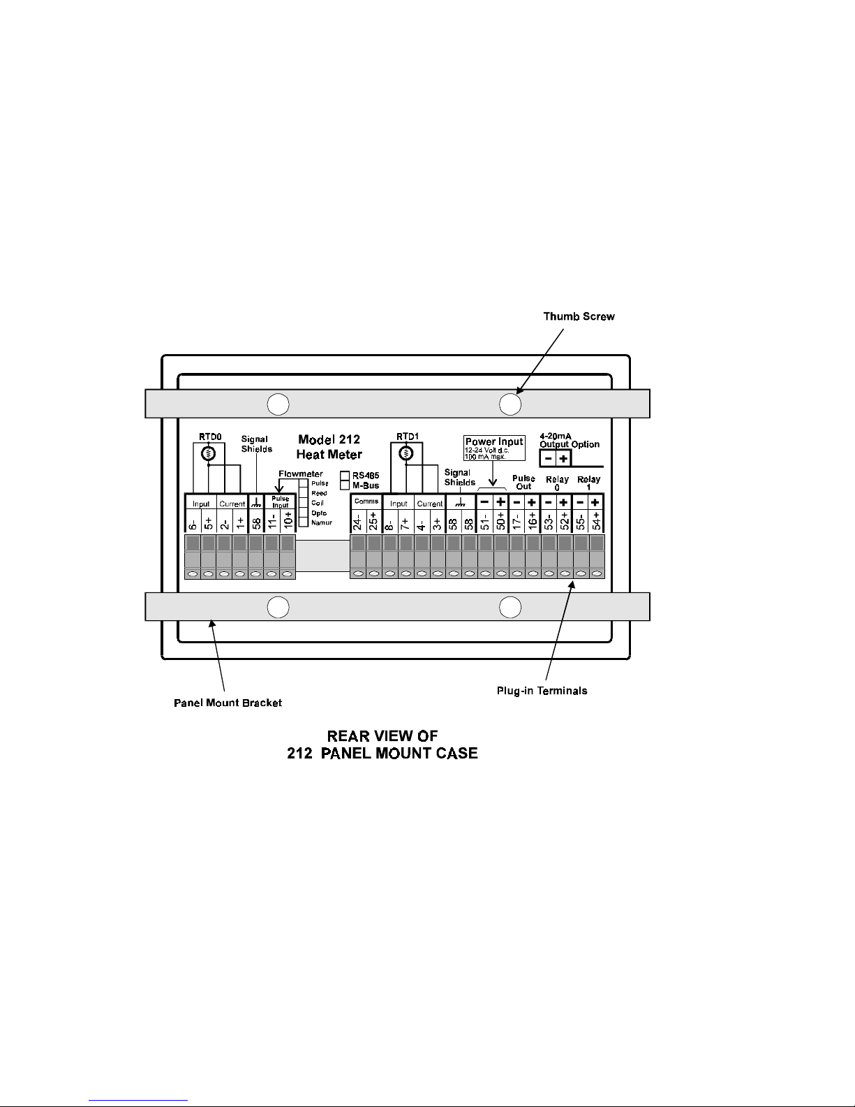
7.2 PANEL MOUNT VERSION
The panel mount version of the Model 212 is supplied with two panel
mount brackets and plug-in terminals which are accessible from the rear of
the instrument.
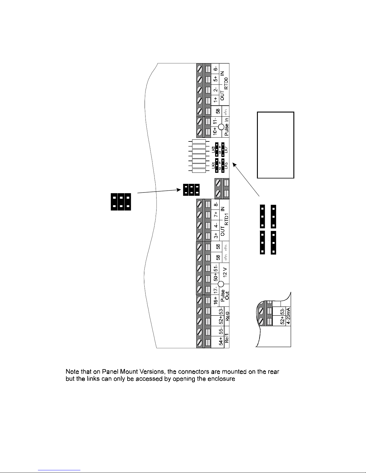
A diagram of the rear panel is shown below. Note that access to the Input
Circuit Links 1-3 and Communication Links 4-7 can only be obtained by opening
the instrument. Access is not available via the rear panel.
The cutout for the panel mount version is 141mm (5.55") wide x 87mm
(3.43") high.
Page 65

212-M-V2.1
Installation 63
7.3 REMOVING THE FRONT PANEL
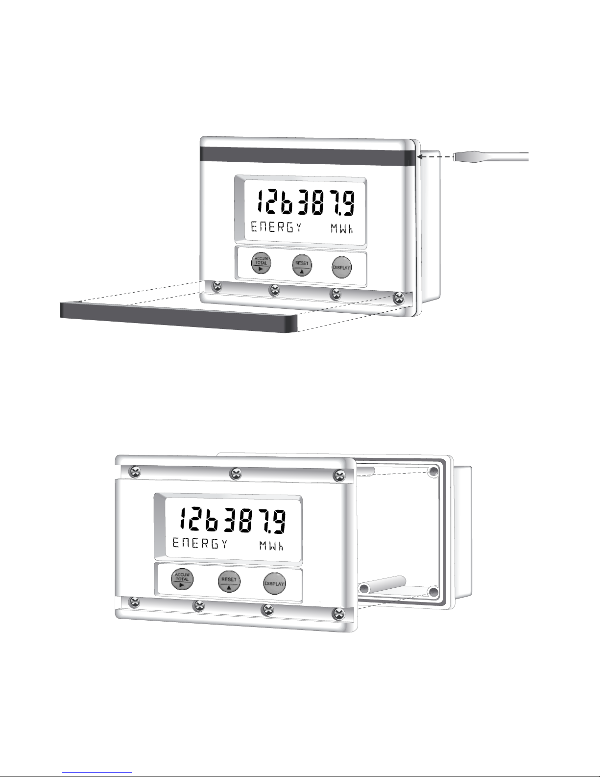
The front of the instrument is removed as follows:
1. Remove both the top and bottom cover strips (ie. the dark plastic
strips on the front) by using a screwdriver to lever up one end.
2. Undo the seven screws retaining the front. Note: The screws should
not be removed from the front panel as they are retained by O-rings.
3. Pull the front panel free from the housing.
Replacing the front panel of the instrument is the reverse procedure.
However, ensure that the front panel is aligned at both connector points
before tightening the screws.
Page 66
212-M-V2.1
64 Installation
Page 67
212-M-V2.1
Installation 65
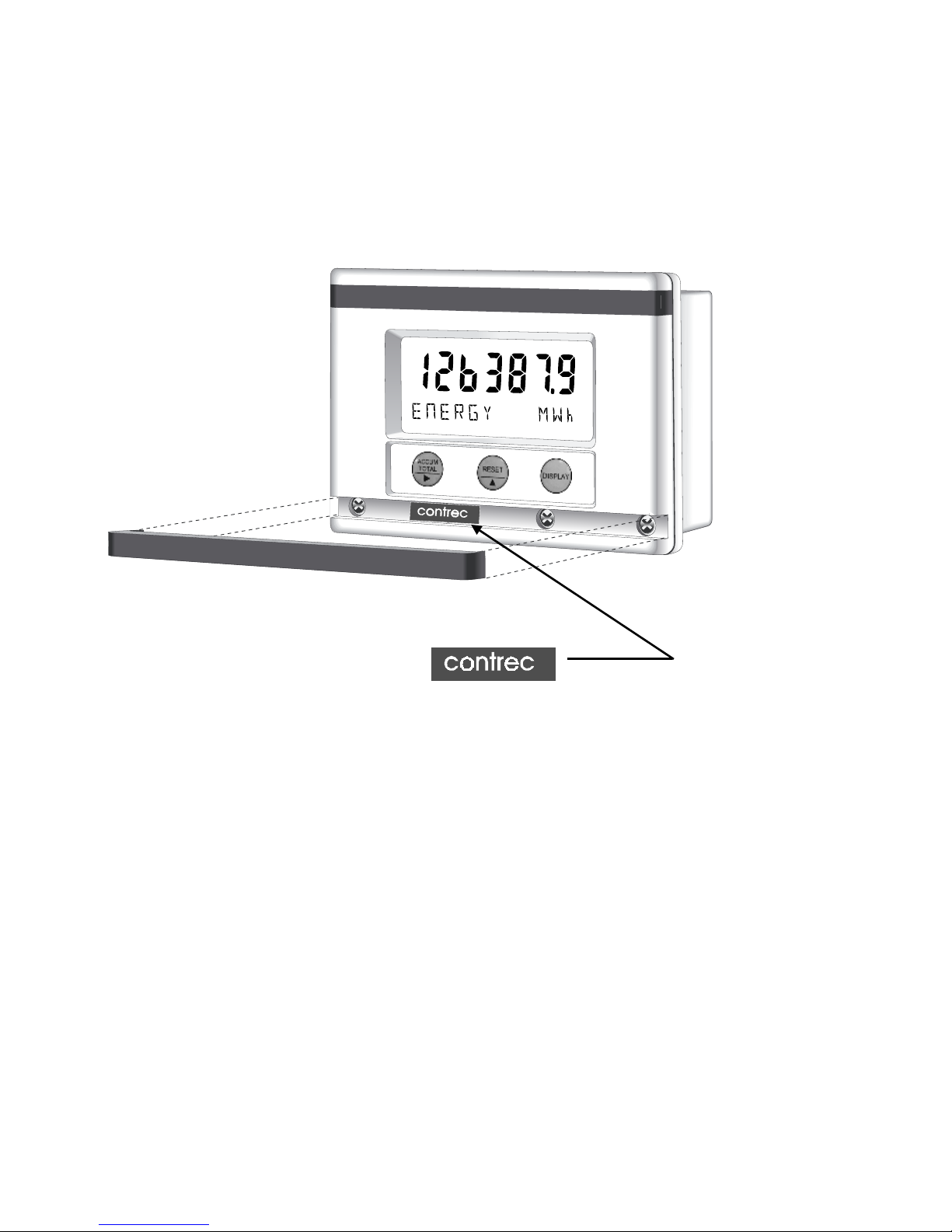
7.4 VERIFICATION SEAL
A Verification Seal is supplied with the instrument and can be placed across
the calibration switch to prevent unauthorised tampering. The seal is made
from a self adhesive material which is destroyed if the seal is broken.
Verification Label for Calibration.
Page 68

212-M-V2.1
66 Installation
7.5 WIRING PRACTICES
Three of the terminals are marked and must be connected to a good earth,
using a multi-stranded, braided wire.
It is good wiring practice to use shielded cables for all connections to the Model
212. Care must be taken to separate signal cables from power cables and
relay cables, so as to minimise interference.
Overall shields should be connected at the instrument side only and to the terminals
marked . These connections should be as short as possible.
In order to comply with the requirements for Electromagnetic Compatibility as per
EMC Directive 89/336/EEC of the Council of the European Community, this
wiring practice is mandatory.
Although it is possible to connect shields to the (-) volt supply terminal (51 -), this
practice is not in accordance with the EMC Directive.
Page 69
212-M-V2.1
Installation 67
TERMINATION BOARD
LK1
LK2
LK3
Input
Circuit
Links
LK1
LK2
LK3
LK4
LK5
LK6
LK7
Communication Links
LK4 LK5
M-Bus A A
RS485 B B
A
B
A
B
4-20mA
Option
Page 70

212-M-V2.1
68 Installation
7.6 TERMINAL DESIGNATIONS
Terminal numbering is in accordance with international standards.
Terminal Description
1 + Feed line RTD0 Current (+)
2 - Feed line RTD0 Current (-)
3 + Return line RTD1 Current (+)
4 - Return line RTD1 Current (-)
5 + Feed line RTD0 Input (+)
6 - Feed line RTD0 Input (-)
7 + Return line RTD1 Input (+)
8 - Return line RTD1 Input (-)
10 Flow Signal Input
11 Flow Signal Reference
16 + Pulse Output (+)
17 - Pulse Output (-)
24 Meter-bus or RS485 (-)
25 Meter-bus or RS485 (+)
50 + 12 Volts Supply (+)
51 - 12 V olts Supply (-)
52 + Relay 0 (+) dc Voltage Only or 4-20mA (+)
53 - Relay 0 (-) dc Voltage Only or 4-20mA (-)
54 + Relay 1 (+) dc Voltage Only
55 - Relay 1 (-) dc Voltage Only
58 Shields
Page 71

212-M-V2.1
Index 69
Index
A
ACCUM TOTAL
Key, 12
Accuracy Class, 7
Alarm Relay Outputs, 56
B
Batteries, 53
BTU, 6
Bus Address, 21
Bus Hardware, 21
C
Cable Length, 8
Charge/Discharge, 27
Check Set-up
Parameters, 19
Coils, 50
Connections, 48
Construction, 9
Conversion Factors, 6
Cooling, 27
Cover Strips, 63
Cut-off, 25
D
DISPLAY Key, 12
Display Mode, 11
E
EMC, 4
EMC Directive, 66
Emission, 4
EN1434, 3
Energy
Measured, 13, 17,
18
Enthalpy, 3
F
Flowmeter Input, 48
Frequency
Cut-off, 19, 25
H
Heating, 27
Heating/Cooling
Mode, 27
High Alarms, 20
I
IEC870-5, 31
IEC751, 7
Infra-red
Communication, 33
Input Connections,
48
Installation, 60
K
kBTU, 6
Key Switches, 12
K-factor, 19
K-factor Range, 8
L
Language, 19
Lead Lengths, 52
Links, 48
Location, 20
Logging, 29
M
Mains Powered, 53
M-bus
(refer Meter-bus), 31
Meter-bus, 31
Metric, 19
Modbus RTU, 34
Model Number, 5
Mounting, 60
N
Namur Switch, 51
O
Off-Peak and Peak, 28
Offset Function, 20, 26
OIML, 3
Operating Modes, 27
Operating Time, 15
Operation, 11
Opto-Sensors, 51
Output Connections,
48
P
Panel Mount, 62
Parity, 21
Peak and Off-Peak, 28
Peak Power, 14
Platinum, 52
Power, 3
Power Adapter, 53
Power Requirements,
8
Power Supply, 53
Pressures, 3
Protocol, 31
Pulse Inputs, 48
Pulse Output, 21, 54
Page 72

212-M-V2.1
70 Index
R
Reed Switch, 50
Relay, 20
Relays, 56
RESET Key, 12
Reverse Polarity, 55
RS485, 34
RTD Input, 52
S
Sensor Type, 8
Set point, 20
Set-up Mode, 42
Shielded Cables, 66
Shields, 66
Software Revision, 23
Solid State dc Relays, 56
Specification, 7
T
Temperature
Difference, 7
Temperature Range, 7
Terminal
Designations, 68
Termination Board, 67
Ton, 6
U
Units of
Measurement, 24
V
Verification Seal, 65
W
Wall Mounting, 60
Wiring Practices, 66
Z
Zero, 26
 Loading...