

contoure RV-500-OTR Installation Instructions Manual
tr
Tf
NTE]
U
RE'"
ispace
sAVER
AppLrANtrEs
Model:
RV-500-OTR
Installation
lnstructions
0ver
the
Range
Microwave
0ven
BEFORE
YOU
BEGIN
Read
these instructions
completely
and
carefully.
'
IMPORTANT
-
Savethese
instructions
for local
inspector's
use.
IMPORTANT
-
observearr
governing
codes
and
ordinances.
Note
to
Installer
-
Be
sure
to leave
these
instructions
with
the
Consumer.
Note
to Consumer
-
Keep
these
instructions
for future
reference.
Skill level
-
Installation
of this
appliance
requires
basic mechanical
and
electrical
skills.
Proper installation
is
the responsibility
of the
installer.
Product
failure
due
to improper
installation
is
not
covered
under
the Warranty.
READ
CAREFULLY.
KEEP
THESE
INSTRUCTIONS.
Installation
Instructions
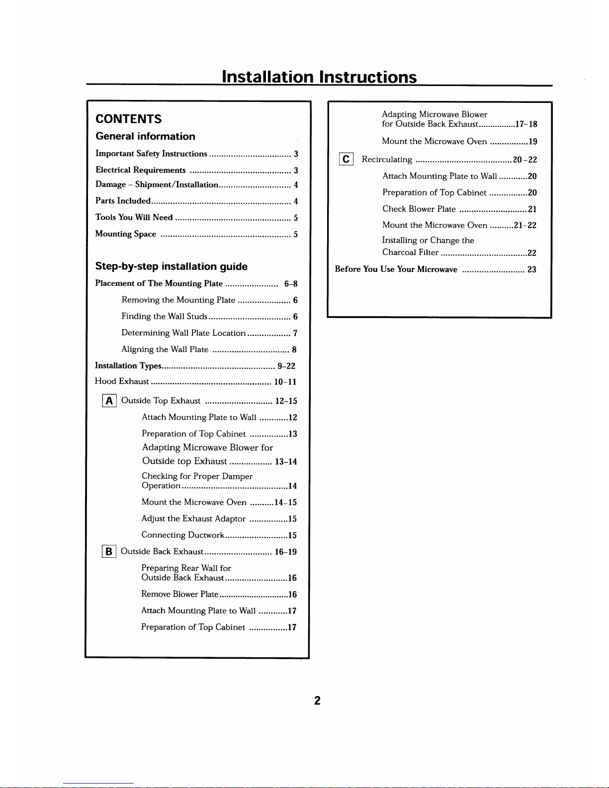
CONTENTS
General
information
Important
Safety Instructions ...........
.......
3
Electrical
Requirements
.......
...................
3
Damage
-
Shipment,/Insta11ation..............................
4
Parts Included.
......... 4
Tools You
Will
Need
................
5
Mounting
Space
......
5
Step-by-step
installation guide
Placement
of The
Mounting Plate
6-8
Removing
the Mounting
Plate
......
6
Finding
the Wall
Studs ..................
6
Determining
Wall Plate
Location
..................
7
Aligning
the
Wall Plate
................
8
Installation
Types...
............
g-22
Hood
Exhaust
.. 10-f l
[A
I
O",.ide Top
Exhaust
12-15
Attach
Mounting
Plate
to Wall ............12
Preparation
of Top
Cabinet ................
I 3
Adapting
Microwave
Blower for
Outside top
Exhaust..........
13-14
Checking
for Proper
Damper
Operation
............14
Mount
the Microwave
Oven ..........14-15
Adjust
the Exhaust Adaptor
................ I
5
Connecting
Ductwork..........................
I
5
I
B
I
Outside
Back
Exhaust...
16-19
Preparing
Rear
Wall for
Outside Back
Exhaust...
.......16
Remove
Blower Plate........
......16
Attach
Mounting
Plate
to Wall
............17
Preparation
of Top
Cabinet ................
I 7
Adapting Microwave
Blower
for
Outside Back Exhaust................
17- 18
Mount
the
Microwave
Oven ................19
Recirculating
.........
20
-22
Attach Mounting
Plate
to Wall ............20
Preparation
of
Top
Cabinet
................ 20
Check
Blower Plate
............21
Mount
the Microwave
Oven ..........21-22
Installing or
Change the
Charcoal Filter
....22
Before You
Use Your
Microwave
..........23
2
lnstallation
Instructions
IMPORTANT
SAFETY
INSTRUCTIONS
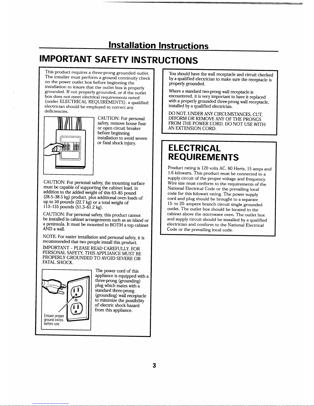
This
product
requires
a
three-prong
grounded
outlet.
The
installer
must perform
u
g.o,r.rA
.ontinuity
check
on the
power
outlet
box
before
beginning
the
installation
to
insure
that
the
outlet
box ii properly
grounded.
If
not
properly
grounded,
or if
ine
buttlt
box
does
not
meet
electrical
requirements
noted
(under
ELECTRICAL
REQUIREMENTS),
a qualified
electrician
should
be
employed
to
correcr
any
deficiencies.
CAUTION:
For
personal
safeff,
remove
house
fuse
or
open
circuit
breaker
before
beginning
installation
to
avoid
severe
or fatal
shock
injury.
CAUTION:
For personal
safety,
the
mounting
surface
must
be
capable
of
supportingthe
cabinet
lold,
in
addition
to
the
adrled
weight
of
*ris
63-95
pound
(28.5-38.5
kg)
product,
plus
additional
oven
loads
of
yp
to
!0
pounds (22.T
kd
or a
totat
weight
of
113-135
pounds
(51.3-01.2
kg).
CAUTION:
For
personal
safety,
this product
cannot
be
installed
in
cabinet
arrangements
such
as
an
island
or
ap-eninsula.
It
must
be
mounted
to
BOTH
a
top
cabinet
AND
a
wall.
NOTE:
For
easier
installation
and personal
safety,
it is
recommended
that
two
people
install
this produit.
IMPORTANT
_
PLEASE
READ
CAREFULLY.
FOR
PERSONAL
SAFETY,
THIS
APPLIANCE
MUST
BE
PROPERLY
GROUNDED
TO
AVOID
SEVERE
OR
FATAL
SHOCK.
The power
cord
of
this
appliance
is
equipped
with
a
three-prong
(grounding)
plug
which
mates
with
a
standard
three-prong
(grounding)
wall
receptacle
to minim2e
the
possibility
of
electric
shockhazard
"
from
this
appliance.
You
should
have
the
wall receptacle
and
circuit
checked
by
a
qualified
electrician
to
make
sure
the
receptacle
is
properly
grounded.
Where
a standard
twoprong
wall receptacle
is
encountered,
it is
very
important
to have
it
replaced
yth.q
properly
qolnled
threeprong
wall
reieptacle,
installed
by
a
qualified
electrician.
DO
NOT,
UNDER
ANY
CIRCUMSTANCES,
CUf,
DEFORM
OR REMOVE
ANY
OF THE
PRONGS
FROM
THE
POWER
CORD.
DO
NOT
USE
WITH
AN
EXTENSION
CORD.
ELECTRICAL
REQUIREMENTS
Product
rating
is 120
volts
AC,
60
Hertz,
15
amps
and
1.6
kilowatts.
This
product
must
be
connected
to
a
supply
circuit
of
the proper
voltage
and
frequency.
Wire
size
must
conform
to
the
requirements
of the
National
Electrical
Code
or
the prevailing
local
code
for
this
kilowatt
rating.
The power
supply
cord
and plug
should
be
brought
to
a separate
15-
to
20-
ampere
branch
circuit
single
giounded
outlet.
The
outlet
box
should
be located
in
the
cabinet
above
the microwave
oven.
The
outlet
box
and
supply
circuit
should
be installed
by a qualified
electrician
and
conform
to
the
National
Electrical
Code
or the
prevailing
local
code.
3
lnstallation
Instructions
DAMAGE-SHIPMENT/
INSTALLATION
'
If
the
unit is
damaged
in
shipment,
return
the
unit
to the
store
in which
it
was
bought
for
repair
or replacement.
o
If
the
unit
is
damaged
by the
customer,
repair
or
replacement
is
the responsibility
of the
customer.
'
If the
unit
is
damaged
by the
installer
(if
other
than
the
customer),
repair
or replacement
must
be
made
by
arrangement
between
customer
and installer.
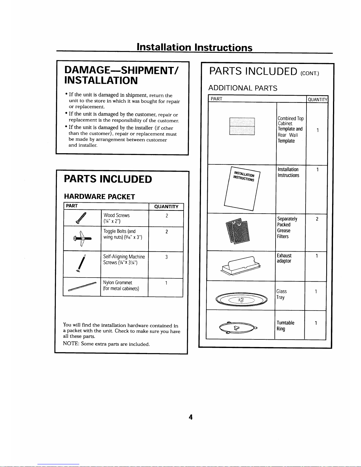
PARTS
INCLUDED
(coNr)
ADDITIONAL
PARTS
PART
QUANTIN
Combined
Top
Cabinet
Template
and
Rear
Wall
Template
1
Installation
Instructions
1
Separately
Packed
Grease
Filters
2
Exhaust
adaptor
1
Glass
Tray
1
Tumtable
Ring
1
HARDWARE
PACKET
PART
QUANTITY
c
Wood
Screws
(1/q"
x
2")
L
Toggle
Bolts
(and
wing
nuts)
(3/0"
x
3")
2
/
Self-Aligning
Machine
Screws
(%"x
3%")
Nylon
Grommet
(for
metal
cabinets)
1
I
PARTS
INCLUDED
You
will
find
the
installation
hardware
contained
in
a
packet
with
the
unit.
Check
to
make
sure
vou
have
all
these
parts.
NOTE:
Some
extra
parts
are included.
4
I
nstal
lation
I nstructions
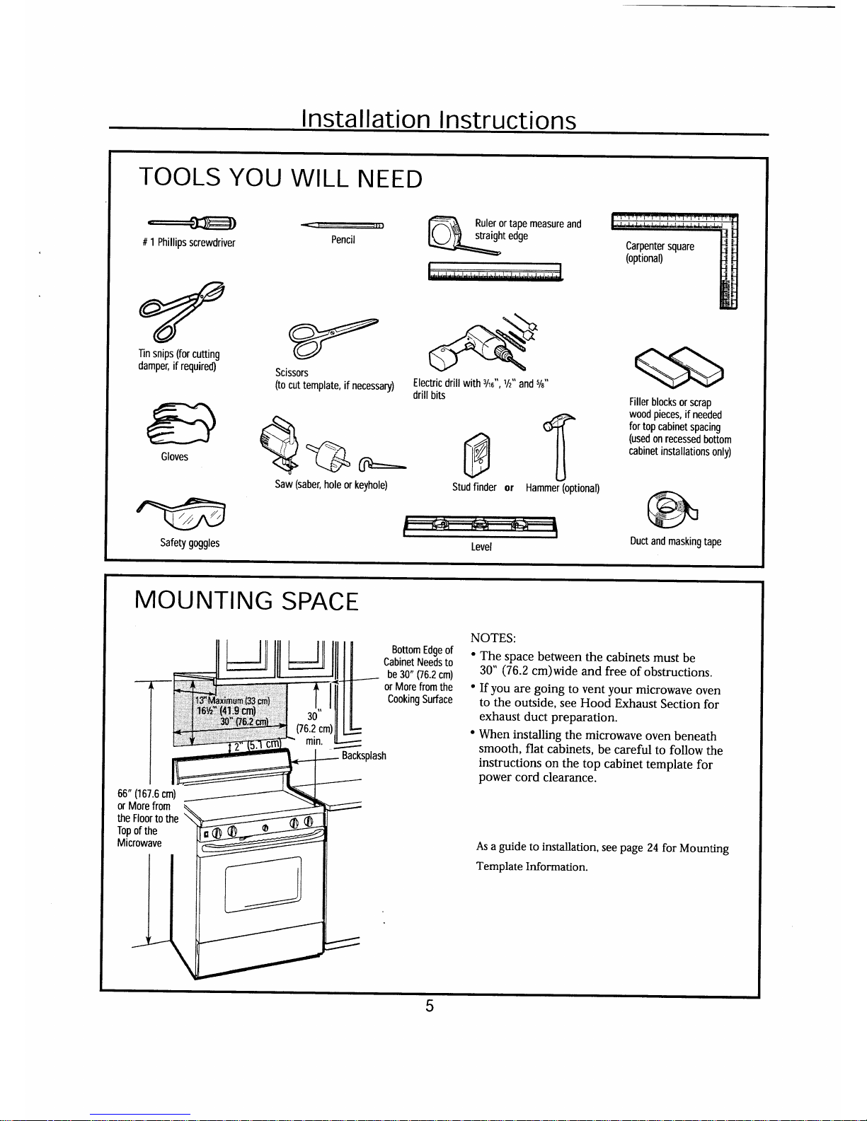
TOOLS
YOU
WILL
NEED
___€1lElt
# 1 Phillips
screwdriver
Iin
snips
(for
cutting
damper,
if required)
lr
ffi
Gloves
nx=fr
VJY)
Safety goggles
Pencil
ffiN
Scissors
\J'l
-\
(to
cut
template,
if necessary)
:I,:ifilor"'
with
3/r0",
%" and
%"
Vl\r\ ffil
S(SF-
V
u
Saw
(saber,
hole
or
keyhole)
Stud finder
or
Hammei(optional)
Filler
blocks
or
scrap
wood pieces,
if
needed
for
top
cabinet
spacing
(used
on recessed
bottom
cabinet
installations
only)
@
Duct
and masking
tape
Level
MOUNTING
SPACE
Bottom
Edge
of
Cabinet Needs
to
be
30"
(76.2
cm)
or
More from
the
Cooking
Surface
NOTES:
'
The
space
between
the
cabinets
must
be
30"
(76.2
cm)wide
and free
of obstructions.
'
If
you
are going
to
vent your
microwave
oven
to the
outside,
see
Hood
Exhaust
Section
for
exhaust
duct
preparation.
'
When
installing
the
microwave
oven
beneath
smooth,
flat
cabinets,
be
careful
to
follow
the
instructions
on
the top
cabinet
template
for
power
cord
clearance.
30
(76.2
cm)
min.
66"
('167.6
cm)
or
More from
the Floor
to
the
Top
of
the
Microwave
As
a
guide
to installation,
see
page
24
for
Mounting
Template
Information.
5
I nstal lation I nstructions
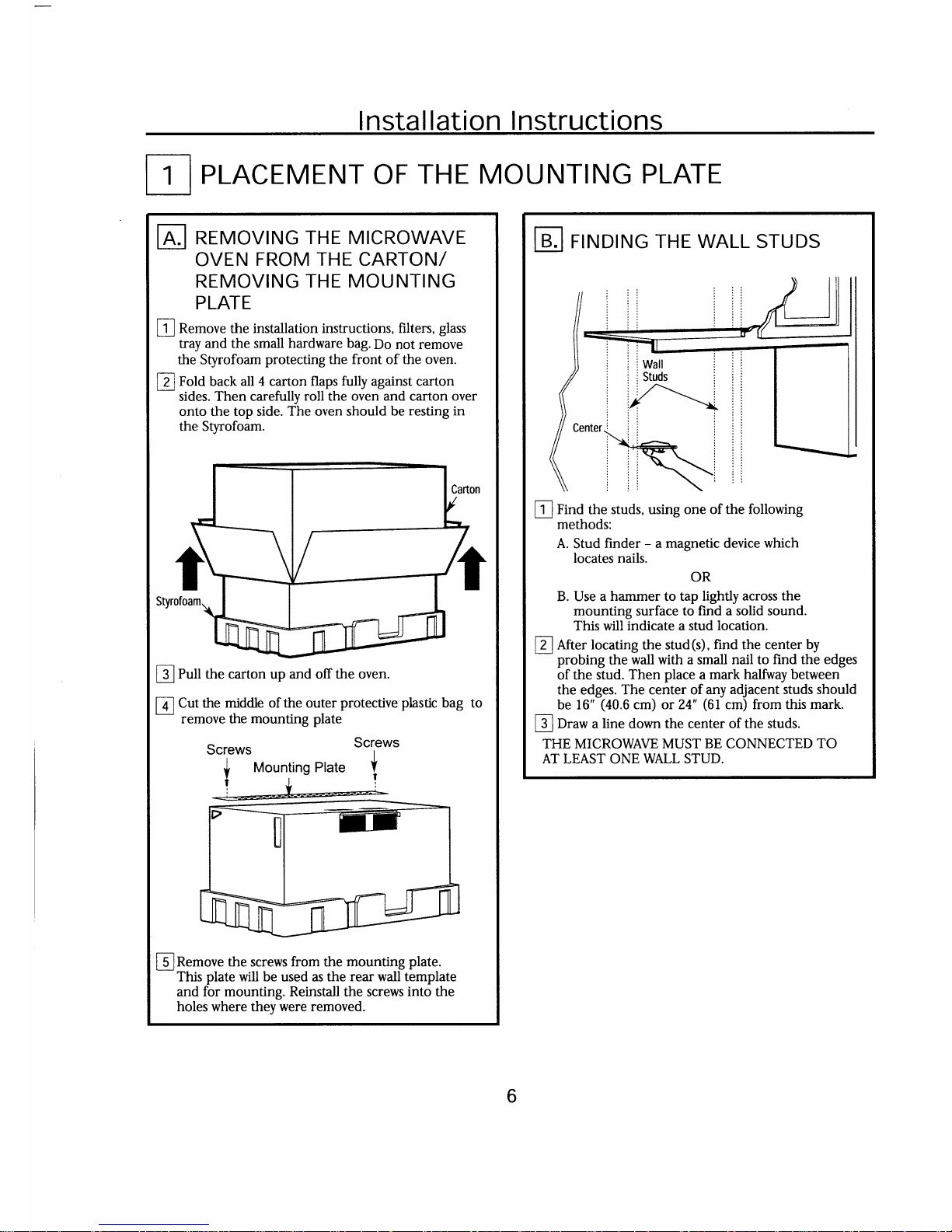
lj_l
PLACEMENT OF
THE MOUNTING
PLATE
tr
REMovTNG
THE MrcRowAVE
OVEN
FROM THE CARTON/
REMOVING
THE MOUNTING
PLATE
I
R"rnove the installation
instructions, filters,
glass
tray
and the small hardware bag.
Do not remove
the
Styrofoam
protecting the front of the oven.
pl
fota
back
all 4 carton flaps fully against carton
-
sides.
Then
carefully
roll
the oven and carton over
onto the top side.
The
oven
should be
resting in
the Styrofoam.
l]_j
Pull the
carton
up and off the oven.
Mounting Plate
[Jl
Cut the
middle of the outer
protective plastic
bag to
-
remove the
mounting
plate
Screws
Y
!
|
5
lRemove
the screws from the mounting
plate.
This
plate
will be used as the
rear wall template
and
for mounting. Reinstall the
screws
into the
holes where they were removed.
6
tr
FINDING
THE WALL
STUDS
l_l
Find
the
studs, using one of the
following
methods:
A.
Stud
finder
-
a
magnetic
device
which
locates nails.
OR
B. Use a
hammer to tap lightly across
the
mounting surface
to find a solid sound.
This will indicate a stud
location.
@
Rt"r locating the stud(s),
find the center by
probing
the
wall with a small nail to
find
the
edges
of the stud.
Then
place
a
mark halfiray between
the edges.
The center of any
adjacent
studs
should
be 16"
(40.6
cm)
or 24'
(61cm)
from this mark.
@
O..* a
line
down the center
of the studs.
THE MICROWAVE
MUST BE CONNECTED
TO
AT LEAST ONE
WALL
STUD.
Instal
lat ion
Inst
ruct
ions
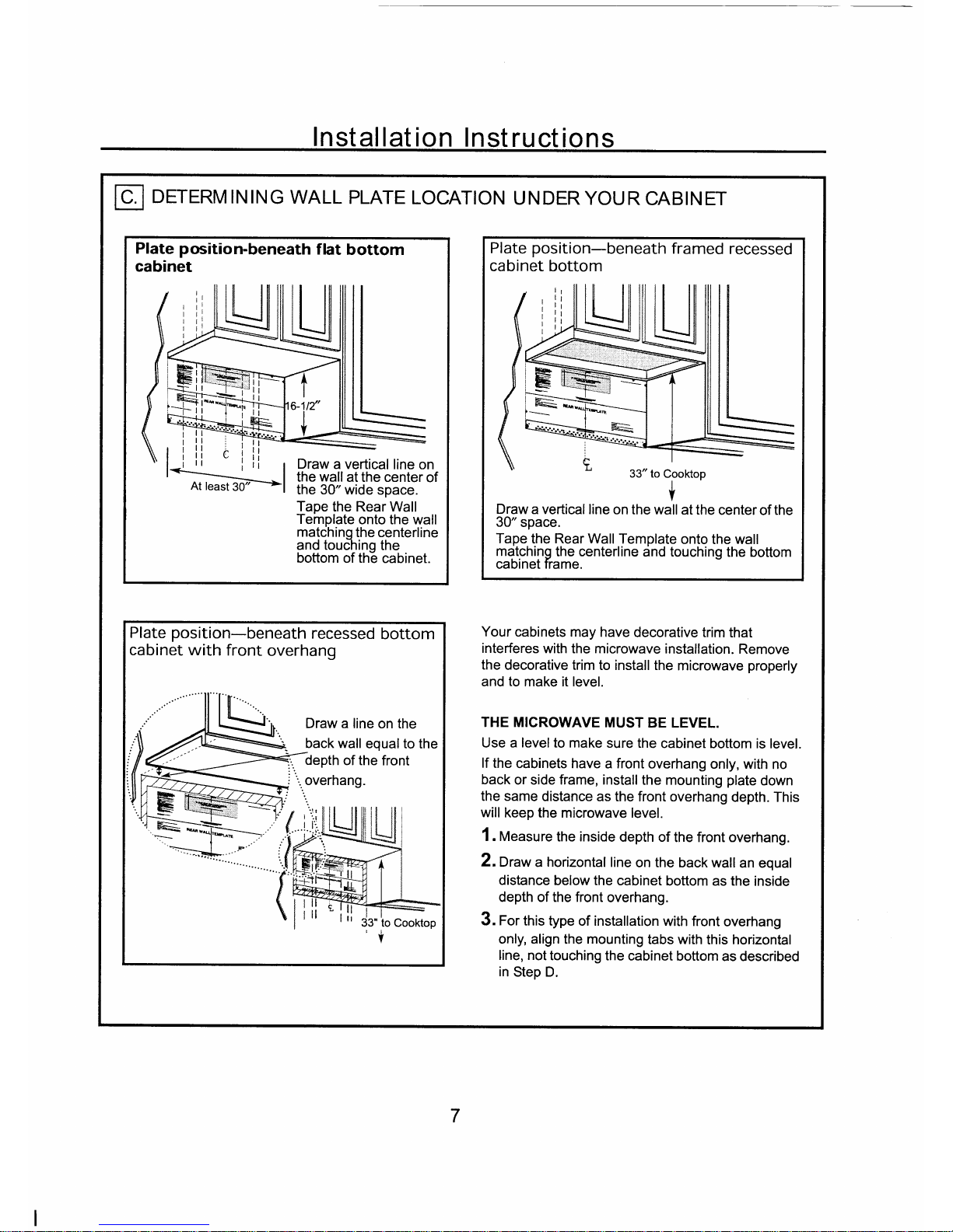
tr
DETERM
IN IN
G
WALL
PLATE
LOcATIoN
U
N DER
YoU R
CABIN ET
Plate
position-beneath
flat
bottom
cabinet
Draw
a vertical
line on
the wall
at the center
of
the 30" wide
space.
Tape
the Rear Wall
Template
onto the wall
matchino
the centerline
and touclrino
the
bottom of thE
cabinet.
Plate
position-beneath
recessed
bottom
cabinet with
front
overhang
Draw a
line on the
back wall
equal to
the
depth
of the
front
,
overhang.
Your
cabinets
may have
decorative trim
that
interferes
with
the
microwave
installation.
Remove
the
decorative trim
to install the
microwave
properly
and
to
make it level.
THE MICROWAVE
MUST
BE LEVEL.
Use a level to make
sure the
cabinet
bottom is level.
lf
the
cabinets have
a front overhang
only, with
no
back
or side frame, install
the mounting
plate
down
the same
distance
as the front overhang
depth. This
will
keep the
microwave level.
1 . Measure
the inside
depth of
the front overhang.
Z.Draw
a
horizontal
line
on the
back watl
an equal
distance below the
cabinet
bottom as the
inside
depth of the front
overhang.
3. For this type
of installation
with front
overhang
only, align
the
mounting
tabs with
this horizontal
line, not
touching
the cabinet
bottom
as described
in
Step D.
Plate
position-beneath
framed
recessed
cabinet bottom
v
Draw
a vertical
line on the wall
at the
center
of
the
30"
space.
Tape
the
Rear Wall
Template
onto
the wall
matching
the centerline
dnd touching
the bottom
caDrnet Trame.
33" to
Cooktop
7
I nstal
lation
I nstructions
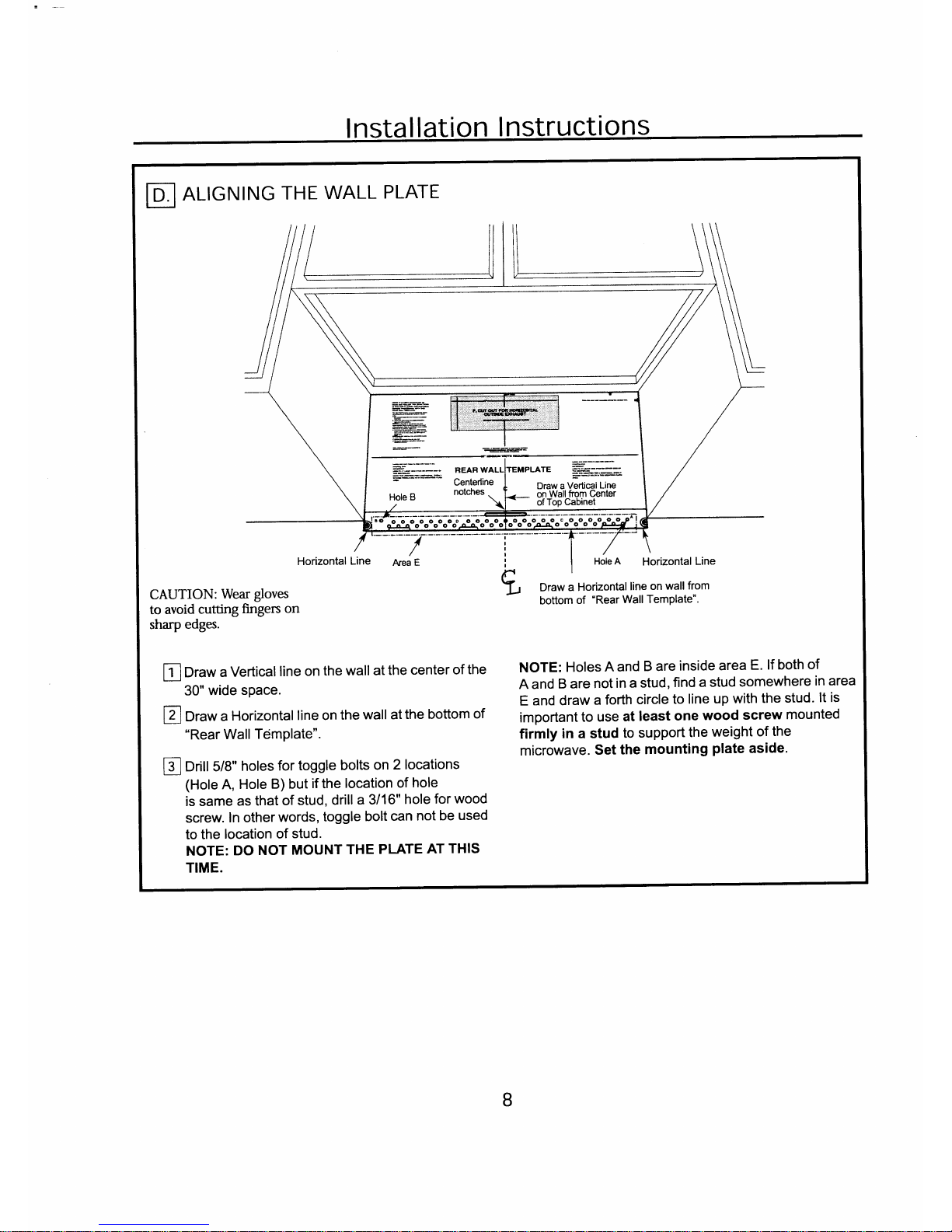
tr
ALIGNING
THE
WALL
PLATE
CAUTION:
Wear
gloves
to
avoid
cutting
fingers
on
sharp
edges.
Draw
a Horizontal
line
on
wallfrom
bottom
of
"Rear
Wall TemPlate".
lil
Draw
a
Vertical
line
on
the wall
at
the
center
of
the
NOTE:
Holes
A and
B are
inside
area
E'
lf both
of
A and
B are
not
in a
stud,
find
a stud
somewhere
in area
E
and draw
a forth
circle
to
line
up
with
the
stud'
lt is
important
to
use
at
least
one
wood
screw
mounted
firmly
in a stud
to
support
the
weight
of
the
microwave.
Set
the
mounting
plate
aside'
30"
wide
space.
l7l Or"*
a
Horizontal
line on
the
wall atthe
bottom
of
"Rear
Wall
Tdmplate"
lsl
oritt 5/8"
holes
for
toggle
bolts
on
2
locations
(Hole
A,
Hole
B) but
if
the
location
of
hole
is same
as
that
of
stud,
drill
a 3/16"
hole
for
wood
screw.
In other
words,
toggle
bolt
can
not
be
used
to the
location
of
stud.
NOTE:
DO
NOT
MOUNT
THE
PLATE
AT
THIS
TIME.
#i.]==
nern
wru{TEMPLATE
k
Centerline |
^'.,.,
-
'i*,-,,
,^^uerrterrrrtt
I Draw a
Vertical
Line
Hole
B
notches
..
l.-
opflal!.f,rm
c'enter
ffi".r;,"+;;;;t'41
o
^o^ooooooooooo-oLooo
oo
8
 Loading...