

Page 1

Group or Division Here
Industrial Fluid Solutions
PC440i Crimper
with CrimpIQ™ Controller
Operator Manual
www.contitech.us
www.contitech.us
Page 2

2 PC440i Crimper – Operator Manual
Table of Contents
PC440i Safety Precautions ...................................................................................................................................................................................................................................................................................................................... 4
PC440i Initial Crimper Setup .................................................................................................................................................................................................................................................................................................................5
High-Level CrimpIQ™ Controller Capabilities...................................................................................................................................................................................................................................................................6
CrimpIQ™ supports the following features.............................................................................................................................................................................................................................................................6
PC440i Series ............................................................................................................................................................................................................................................................................................................................................................ 7
PC440i Features ....................................................................................................................................................................................................................................................................................................................................................8
Initial Crimper Setup .........................................................................................................................................................................................................................................................................................................................................9
Overview ......................................................................................................................................................................................................................................................................................................................................................... 9
Crimper Operations .......................................................................................................................................................................................................................................................................................................................................10
Logging In .................................................................................................................................................................................................................................................................................................................................................10
Default User Accounts ................................................................................................................................................................................................................................................................................................................10
Navigating the CrimpIQ™ Controller .......................................................................................................................................................................................................................................................................................11
Basic Application Guide ............................................................................................................................................................................................................................................................................................................11
Top Menu ...................................................................................................................................................................................................................................................................................................................................................11
Left Slide-Out Menu Functions .........................................................................................................................................................................................................................................................................................12
Left Slide-Out Menu Information ....................................................................................................................................................................................................................................................................................12
Using the Main Menu ...................................................................................................................................................................................................................................................................................................................................13
CrimpIQ™ controller Main Menu Screen Options ...................................................................................................................................................................................................................................... 13
Crimper Operations .......................................................................................................................................................................................................................................................................................................................................14
Main Crimper Operations Screen .................................................................................................................................................................................................................................................................................14
Load Crimp Speciications .....................................................................................................................................................................................................................................................................................................14
MyCrimp® – Search Screen ...................................................................................................................................................................................................................................................................................................15
Key Functions of MyCrimp® ................................................................................................................................................................................................................................................................................................ 15
MyCrimp® – Results Screen ..................................................................................................................................................................................................................................................................................................16
MyCrimp® – Crimp This Speciication ...................................................................................................................................................................................................................................................................... 17
Managing Crimp Speciications ...................................................................................................................................................................................................................................................................................... 17
Crimp Speciications with Special Handling Requirements ...........................................................................................................................................................................................................18
Favoriting Crimp Speciications .................................................................................................................................................................................................................................................................................................... 19
Editing a Favorite ..............................................................................................................................................................................................................................................................................................................................20
Favorite Special Handling .......................................................................................................................................................................................................................................................................................................20
Crimp to Diameter ...........................................................................................................................................................................................................................................................................................................................................21
MyCrimp® Industrial ...................................................................................................................................................................................................................................................................................................................................... 22
Entering Industrial Measurements ..............................................................................................................................................................................................................................................................................22
Beginning a Crimp ........................................................................................................................................................................................................................................................................................................................................... 24
Loading Dies ...........................................................................................................................................................................................................................................................................................................................................24
Selecting a Die ...................................................................................................................................................................................................................................................................................................................................... 25
Change Die Mode ............................................................................................................................................................................................................................................................................................................................26
Crimp Operations .............................................................................................................................................................................................................................................................................................................................................27
Performing the First Crimp ................................................................................................................................................................................................................................................................................................... 27
Measuring a Crimp ......................................................................................................................................................................................................................................................................................................................... 28
Crimp Operations Screen .......................................................................................................................................................................................................................................................................................................29
Crimp Operations Screen Sections .............................................................................................................................................................................................................................................................................29
Operational Information .......................................................................................................................................................................................................................................................................................................... 30
Crimp Detail Panel ...........................................................................................................................................................................................................................................................................................................................30
Crimp Mode ............................................................................................................................................................................................................................................................................................................................................32
Crimp Information ...........................................................................................................................................................................................................................................................................................................................33
Crimp Management Function Buttons ..................................................................................................................................................................................................................................................................34
Table of Contents
PC440i Crimper with CrimpIQ™ Controller
Page 3

Settings and Support ...................................................................................................................................................................................................................................................................................................................................35
Machine Coniguration ..............................................................................................................................................................................................................................................................................................................36
Machine Coniguration Options ......................................................................................................................................................................................................................................................................................36
Managing Preset Dies .................................................................................................................................................................................................................................................................................................................37
Managing Users .................................................................................................................................................................................................................................................................................................................................38
Self Calibration Mode ...................................................................................................................................................................................................................................................................................................................38
Default User Accounts ............................................................................................................................................................................................................................................................................................................... 38
Maintenance Mode ........................................................................................................................................................................................................................................................................................................................ 39
Setting Up an Internet Connection .............................................................................................................................................................................................................................................................................39
Using an Ethernet Connection .........................................................................................................................................................................................................................................................................................39
Using a Wi-Fi Connection ........................................................................................................................................................................................................................................................................................................40
Connecting to a Captive Portal ........................................................................................................................................................................................................................................................................................40
Verifying Connection Status ................................................................................................................................................................................................................................................................................................40
Testing Proper Connectivity ................................................................................................................................................................................................................................................................................................41
Additional Connection Options .......................................................................................................................................................................................................................................................................................41
Internet Access Requirements ......................................................................................................................................................................................................................................................................................... 41
Backup to CrimpCloud® ............................................................................................................................................................................................................................................................................................................42
General Coniguration .................................................................................................................................................................................................................................................................................................................42
Support .......................................................................................................................................................................................................................................................................................................................................................................... 45
Create a Ticket ...................................................................................................................................................................................................................................................................................................................................... 46
What Happens Next? ...................................................................................................................................................................................................................................................................................................................46
Conti Fluid Solutions ..................................................................................................................................................................................................................................................................................................................... 47
Training Manuals ...............................................................................................................................................................................................................................................................................................................................47
Machine Information ....................................................................................................................................................................................................................................................................................................................47
Other Topics ............................................................................................................................................................................................................................................................................................................................................................ 48
Integrated Caliper Measurements ...............................................................................................................................................................................................................................................................................48
Coniguring CrimpIQ™ Calipers (Bluetooth) .....................................................................................................................................................................................................................................................48
Coniguring CrimpIQ™ Calipers (USB) .....................................................................................................................................................................................................................................................................48
Setting Up USB Calipers ........................................................................................................................................................................................................................................................................................................... 48
Using CrimpIQ™ Calipers .........................................................................................................................................................................................................................................................................................................49
PC440i Lubrication Procedure ......................................................................................................................................................................................................................................................................................................50
PC440i Die Installation and Management ......................................................................................................................................................................................................................................................................51
Adapter Die Installation ..............................................................................................................................................................................................................................................................................................................51
Hydraulic Die Installation ......................................................................................................................................................................................................................................................................................................... 52
PC440i PLC Reset Procedure ............................................................................................................................................................................................................................................................................................................53
Resetting the PLC to Its Original Settings ........................................................................................................................................................................................................................................................... 53
PC440i Troubleshooting ......................................................................................................................................................................................................................................................................................................................... 54
PC440i Component Parts Breakdown ..................................................................................................................................................................................................................................................................................55
PC440i Warranty ...............................................................................................................................................................................................................................................................................................................................................61
CustomCrimp® “No Nonsense” Warranty ............................................................................................................................................................................................................................................................61
3PC440i Crimper – Operator Manual
Table of Contents
PC440i Crimper with CrimpIQ™ Controller
Page 4

4 PC440i Crimper – Operator Manual
SAFETY PRECAUTIONS
• Read instructions and identify all component parts before using the crimper.
i
• PC440i crimper can produce 265 tons of crimping force.
• Keep both hands away from pinch points.
• Consult the Continental Crimp Speciications Manual for correct crimper setting
and crimp measurements.
• Always wear eye protection.
PC440i Safety Precautions
PC440i Crimper with CrimpIQ™ Controller
Page 5
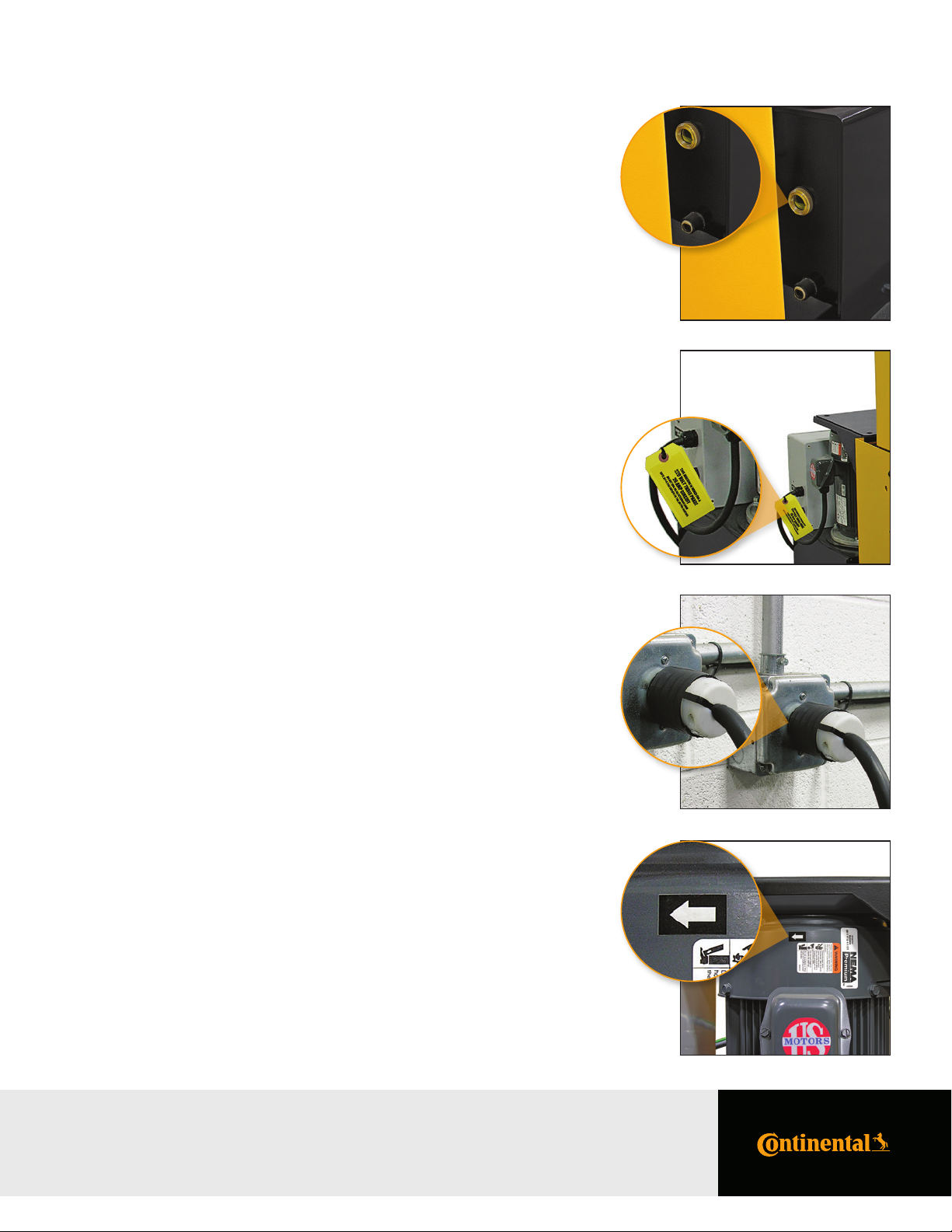
PC440i Initial Crimper Setup
Hydraulic Oil Check: Check the hydraulic oil level in the sight
glass window on the front of the reservoir.
Notes:
• The reservoir requires 8 gallons of ISO grade 46 hydraulic
oil for complete ill.
• If necessary, oil can be drained from either of the two ports
at the bottom of the reservoir.
Voltage Tag Check: Check electrical circuit to be certain that
it matches the crimper’s requirements
shown on the voltage tag attached to the
crimper cord.
5PC440i Crimper – Operator Manual
Notes:
• Plug the PC440i crimper directly into the appropriate electrical circuit/wall outlet.
• Electrical Requirements:
7.5HP/230V/3Phase (20 Amp)
7.5HP/440V480V/3Phase (20 Amp)
5HP/230V/1Phase (30 Amp)
Caution: Do not run the crimper on an extension cord as low voltage
can damage the motor and/or electrical components.
Rotation of the Motor Check to be certain that the motor rotates
Check: in the direction of the arrow shown on the
motor housing.
Caution: Damage to the pump can result if the motor does not rotate
in the correct direction.
PC440i Initial Crimper Setup
PC440i Crimper with CrimpIQ™ Controller
Page 6

6 PC440i Crimper – Operator Manual
High-Level CrimpIQ™ Controller Capabilities
This version of the CrimpIQ™ controller is designed to take full advantage of the tablet interface and the connection to
CrimpCloud®. CrimpCloud® is a web portal that provides users access to crimping and quality results captured in the
CrimpIQ™ controller.
CrimpIQ™ Supports the Following Features
Ease of Use:
• Quick access to simple hydraulic and industrial crimping modes.
• Optional semi and full automatic crimping modes.
• New touchscreen interface with clear, easy to read icon driven operations.
• Integrated measurement tools: Choice of USB wired or Bluetooth caliper provide direct measure
input for crimp, diameters and industrial hose measurements.
• Integrated help and tutorial guides for easy feature reference.
• Ability to easily favorite crimp speciications, complete with notes, for easy reference and accurate repeat crimping.
• Ability to track and report on crimp measurements and crimp pressures.
Integrated Crimping Tools:
• Full integration with MyCrimp®, for easy importing and handling of full crimp speciications.
• Integrated Industrial Crimp Calculator computes appropriate crimp diameter based on hose and itting measurements.
• Support for foot pedal and electronic backstop.
Customizable:
• User account speciic settings, such as choice of millimeters or inches as irst choice for data entry.
• Create individual user logins (4-digit pins) to track usage and restrict machine coniguration.
Connected:
• Wi-Fi or Ethernet connections, for easy reference to manufacturer web content straight from the crimper,
automatic coniguration backup and operations tracking.
• Ability to wirelessly update crimper software, providing up-to-date crimp speciications and new
functionalities to crimper software.
• CrimpCloud® reporting to provide various reports on assemblies, crimps and machine maintenance.
Integrated Support and Maintenance:
• Simple on-crimper support ticket creation, with enhanced technical diagnostics for quicker and more responsive
help when needed most.
• Built-in tutorials and training, including feature tutorials on every screen.
• Dynamic machine maintenance tracking and reporting, showing historical tracking of maintenance.
• Preventive maintenance alerts avoid machine downtime and costly repairs.
• Detailed on-machine availability of machine capacities.
Expansion Options:
• Bluetooth 4.0 supports Bluetooth calipers and other approved accessories.
• 8GB on-device storage, for support of crimp speciications or other future applications.
High-Level CrimpIQ™ Controller Capabilities
PC440i Crimper with CrimpIQ™ Controller
Page 7
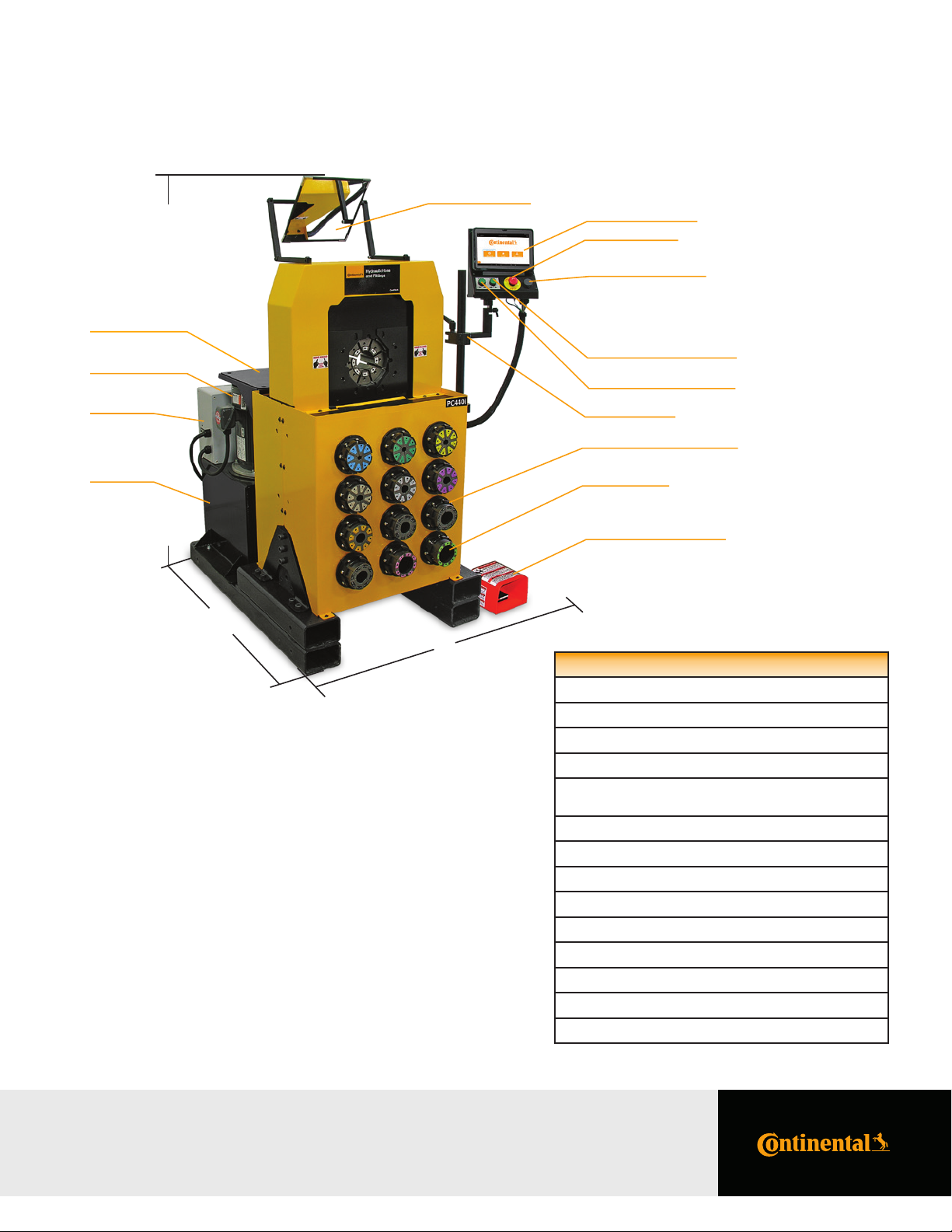
PC440i Series
67"
Back Shelf
7.5 HP Motor High
Capacity Pump
Electrical
Enclosure
7PC440i Crimper – Operator Manual
Adjustable Mirror
CrimpIQ™ Controller
Emergency Stop
Audio and USB Ports
Crimper Head Open Button
Crimper Head Close Button
Adjustable Arm
Built-in Die Storage Pockets
Reservoir
46-½"
Small Footprint for
Minimum Use of Space
99P Die Series
Foot Pedal for Use in Semi
and Full Automatic Mode
52"
PC440i Speciications
Crimping force: 265 Ton
Hose capacity: Max 2SP: 2", 4SP: 2", 6SP: 1-½", Industrial: 4"
Size: L: 46-½" x W: 52" x H: 67"
Weight: 1,840 lbs.
Power: 7.5HP/230V/3Phase (Standard) 7.5HP/440V480V/3Phase (Optional) 5HP/230V/1Phase (Optional)
Hydraulic die series: 99P
Adapter die series: 160MM to 99MM
Industrial die series: 160S
Adjustability: Inch/Metric
Opening w/o dies: 248mm/9.75"
Master die inside diameter: 160mm/6.3"
Master die travel: 102mm/4"
Reservoir capacity: 8 U.S. Gallons
Oil type: ISO 46 Hydraulic Oil
PC440i Series
PC440i Crimper with CrimpIQ™ Controller
Page 8
8 PC440i Crimper – Operator Manual
PC440i Features
Continental CrimpIQ™ controller, the
future of crimping at your ingertips.
Quickly Interchangeable
Adapter Dies.
10-inch color capacitive touchscreen
and user- friendly navigation.
Quick change tool makes die
changes a quick and simple process.
Intuitive screens lead the operator
through the setup and crimping process.
Fixed 6 o’clock die position allows
the operator to place the itting on
bottom die and crimp.
Manual backstop makes hydraulic hose
production crimping fast and accurate.
PC440i Features
PC440i Crimper with CrimpIQ™ Controller
Foot pedal for use in semi and full
automatic mode.
Built-in die storage pockets keeps
frequently used die sets readily available.
Page 9

Initial Crimper Setup
Overview
Before the crimper can be used for the irst time, a brief setup process must be completed. This process sets some initial
parameters, identiies this machine to the CrimpCloud® system and allows the user to conirm the Terms and Conditions
for use of this machine.
This process only needs to be completed once when the machine is installed. After that, the machine will power up and
be ready for use.
9PC440i Crimper – Operator Manual
Initial Crimper Setup
PC440i Crimper with CrimpIQ™ Controller
Page 10

10 PC440i Crimper – Operator Manual
Crimper Operations
Logging In
To begin using the crimper, you must irst login.
The crimper supports multiple users to allow tracking of activities as well as restrict access to some coniguration type functions.
Default User Accounts
The system comes with 3 users already created: admin, machine owner and user. Additional accounts can be added if
required using the machine coniguration menu.
Pin codes listed below are defaults, and they can be changed by machine owners in the user menu:
If you have conigured additional users, their names will appear in this list as well. Once you have logged in, you can begin
using the crimper.
Admin: A private account for certiied technicians and engineering maintenance.
Machine This account is an admin level account intended for the local administration.
Owner: It has full access to all settings and functions. Default pin code is 9876.
User: This account has the permissions and capabilities to perform crimping operations but
has limited access to settings and diagnostics/setup functions. Default pin code is 1234.
Note: The system will automatically log users out of the system after the machine is idle for 1 hour.
This feature can be disabled or conigured in the Machine Coniguration screen.
Crimper Operations
PC440i Crimper with CrimpIQ™ Controller
Page 11
11PC440i Crimper – Operator Manual
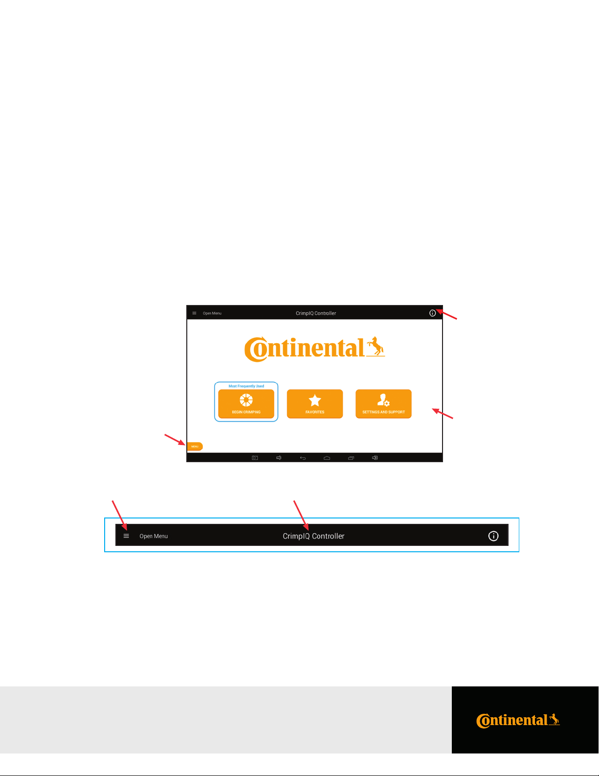
Navigating the CrimpIQ™ Controller
This section provides an introduction to the controller screens and functions that are common throughout the application.
Basic Application Guide
This section outlines basic functions within the app that are common throughout the application. The basic outline and
functionality is common throughout the application.
The screen is divided into the following sections:
Top Menu: This area of the screen provides high-level application and controller information
and access to help and settings.
Main Screen: Main screen with information and functions related to this screen
(directly linked to the screen title).
Left Menu: Provides access to information and functions that need to be available from everywhere
within the application. Access this with the menu button or by “swiping” left to right
from the left side of the screen.
Top
Menu
Left Menu
Access
Main
Screen
Top Menu
The top menu includes a screen title, access to menus and information.
Back/Menu Screen Title Information/Help
Back/Menu: This allows you to return one screen back (when you reach the main menu,
it brings out the left slide-out menu).
Information/Help: This option brings up help information relevant to the speciic location within the app.
Other: There are a few other status indicators that may be helpful.
• Right section displays Wi-Fi strength, Bluetooth status and machine time.
Navigating the CrimpIQ™ Controller
PC440i Crimper with CrimpIQ™ Controller
Page 12
12 PC440i Crimper – Operator Manual
Left Slide-Out Menu
The left slide-out menu is available from anywhere within the Crimp controller app. It can be accessed by pressing the Menu button
(always on the lower left side) or by swiping left from the left side of the screen.
Once opened, pressing anywhere on the right side of the screen (right of the left slide-out menu) will close the menu.
The left menu contains information and functions that could be used at any time within the application.
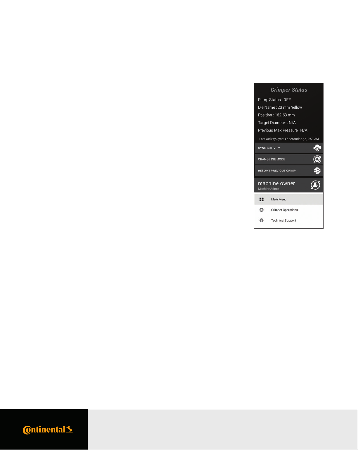
Left Slide-Out Menu Information
The left slide-out menu provides a quick status of the system. This information includes:
Die Name: Name of the die (if any) that is currently loaded in the machine.
Position: Position of the crimp head, relative to the die currently loaded.
Target Diameter: The crimp diameter target currently loaded into the machine.
This is the diameter the crimper will close to given the size of
the dies loaded into the machine.
Previous Max Max pressure on the last successful crimp.
Pressure:
Last Activity Sync:
The last time that the machine has synced with CrimpCloud®.
Left Slide-Out Menu Functions
The left slide-out menu provides functions that can be executed from anywhere at any time:
Sync Activity: Sync Activity sends the latest crimper activity up to CrimpCloud®. Last Activity Sync data and time
described above detail the last successful data sync.
Change Die Mode: This mode allows the user to position the head to change dies. The machine tracks which dies are
loaded and will update information according to which dies are loaded.
"User Name" Change user function. This button displays the currently logged in user and provides a function to
login as a dierent user.
Main Menu: Return to the main menu of the application.
Crimper Return to the crimper operations menu.
Operations:
Technical Support: Bring up the technical support function.
Navigating the CrimpIQ™ Controller
PC440i Crimper with CrimpIQ™ Controller
Page 13

Using the Main Menu
This screen provides the main functions of the crimper.
13PC440i Crimper – Operator Manual
CrimpIQ™ Controller Main Menu Screen Options
Begin Crimping:
This button brings up the functions to perform hydraulic and industrial hose crimping.
Favorites: The Favorites button provides users with direct access to favorited crimp speciications.
Setting and This button brings up all of the support, information, training manuals and coniguration options
Support: available for this machine.
Using the Main Menu
PC440i Crimper with CrimpIQ™ Controller
Page 14

14 PC440i Crimper – Operator Manual
Crimper Operations
Main Crimper Operations Screen
The crimper operations screen is the starting point for setting up a crimping operation.
Favorites: This function contains all of the crimp speciications that have been previously favorited.
Crimp to Diameter: This function allows the user to directly enter a crimp diameter. Once entered, the system
will recommend a die and allow the user to proceed to Crimp Operations.
MyCrimp® Industrial: This brings up an Industrial Crimp Calculator. This calculator can determine the crimper
setup based on the hose diameter or hose wall thickness.
Load Crimp Speciications
This function allows the user to retrieve and load a crimp speciication from MyCrimp®.
Crimper Operations
PC440i Crimper with CrimpIQ™ Controller
Page 15

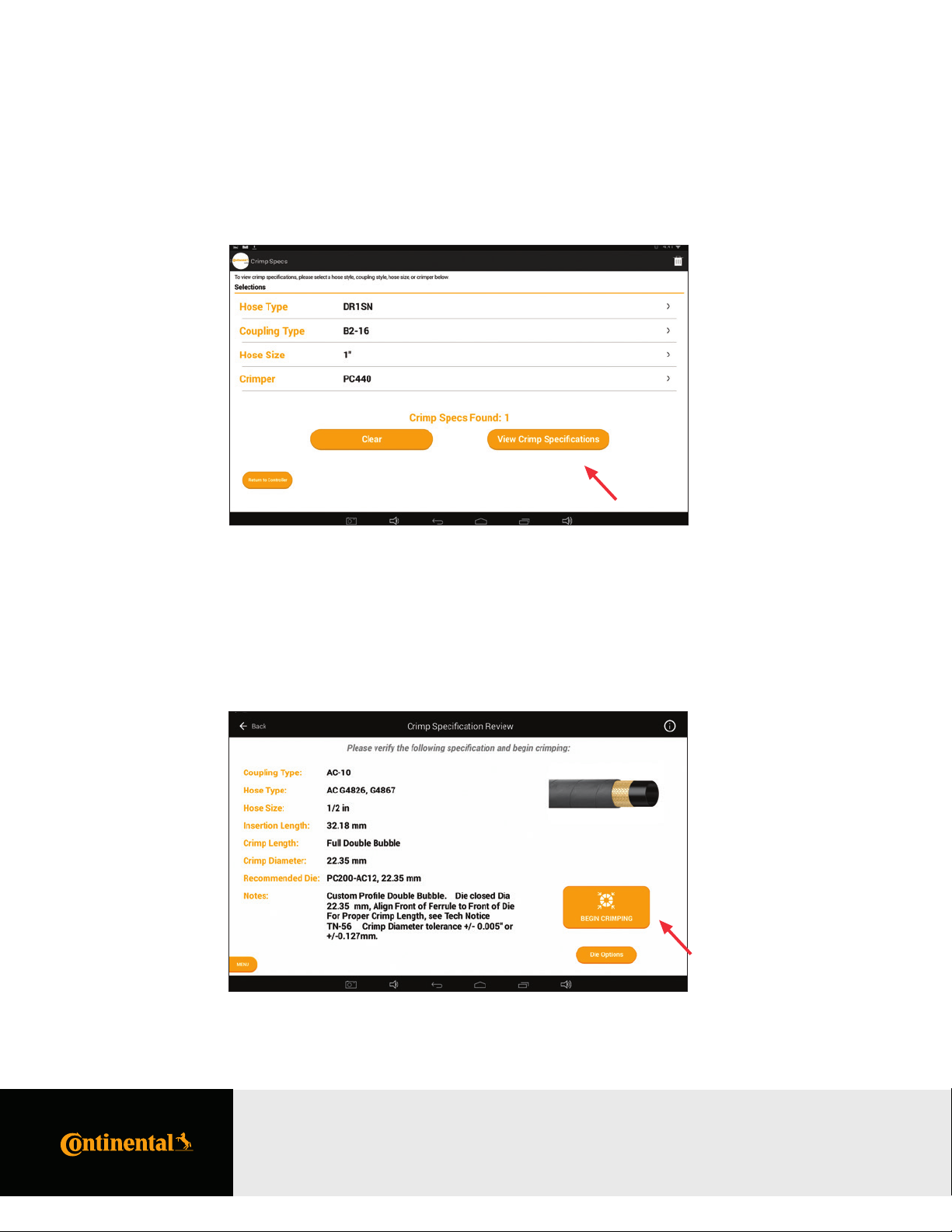
MyCrimp® – Search Screen
Use the Hose Type, Coupling Type and Hose Size to ind the crimp speciications you need.
15PC440i Crimper – Operator Manual
Key Functions of MyCrimp®
Hose Type:
Drill down into a list of hose types.
Coupling Type: Drill down into a list of coupling types.
Hose Size: Drill down into the list of hose sizes.
Crimper: This is preset to the current crimper type and cannot be changed.
Favorite: Allows the user to favorite selections and view them at the top of the list.
Clear: The clear button and trash can icon clear previous selections and let the user
begin a new search.
Total Crimp Specs: Lists the total number of crimp speciications found that match the search criteria.
View Crimp Allows the user to view a list of matching crimp speciications.
Speciications:
Return to controller: Allows the user to abort the MyCrimp® search and return to the controller.
Crimper Operations
PC440i Crimper with CrimpIQ™ Controller
Page 16
16 PC440i Crimper – Operator Manual
Once you ind the desired crimp speciication, View Crimp Speciications will allow users to review the matching
crimp speciications.
MyCrimp® – Results Screen
This view provides a review of the hose and itting selected. Select “Begin Crimping” to begin crimping.
Crimper Operations
PC440i Crimper with CrimpIQ™ Controller
Page 17
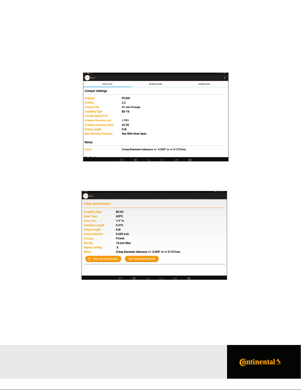
From the detailed view, users can view the full details of the crimp speciications.
Users can return to the previous screen with the Back button in the upper left corner or by using the "More Options" menu
in the upper right to “Export Speciication.” An Export Speciication button is also found below the speciication details.
17PC440i Crimper – Operator Manual
MyCrimp® – Crimp This Speciication
Selecting “Crimp This Speciication” will allow the user to conirm the crimp speciication details.
Managing Crimp Speciications
Begin Crimping: Select this option to have the controller conigure the crimper and allow the operation to load/
conirm the correct die is loaded.
Die Options: In special situations, the user may wish to use an alternative die. To accomplish this, select the
Die Options button to bring up a list of all dies conigured for this machine.
Crimper Operations
PC440i Crimper with CrimpIQ™ Controller
Page 18

18 PC440i Crimper – Operator Manual
Crimp Speciications with Special Handling Requirements
There are cases where the user has to perform additional steps in order to select the correct crimp speciication for the
hose and itting combination. In these cases, MyCrimp® will prompt the user with additional information. Users can
then take the appropriate actions.
Crimper Operations
PC440i Crimper with CrimpIQ™ Controller
Page 19
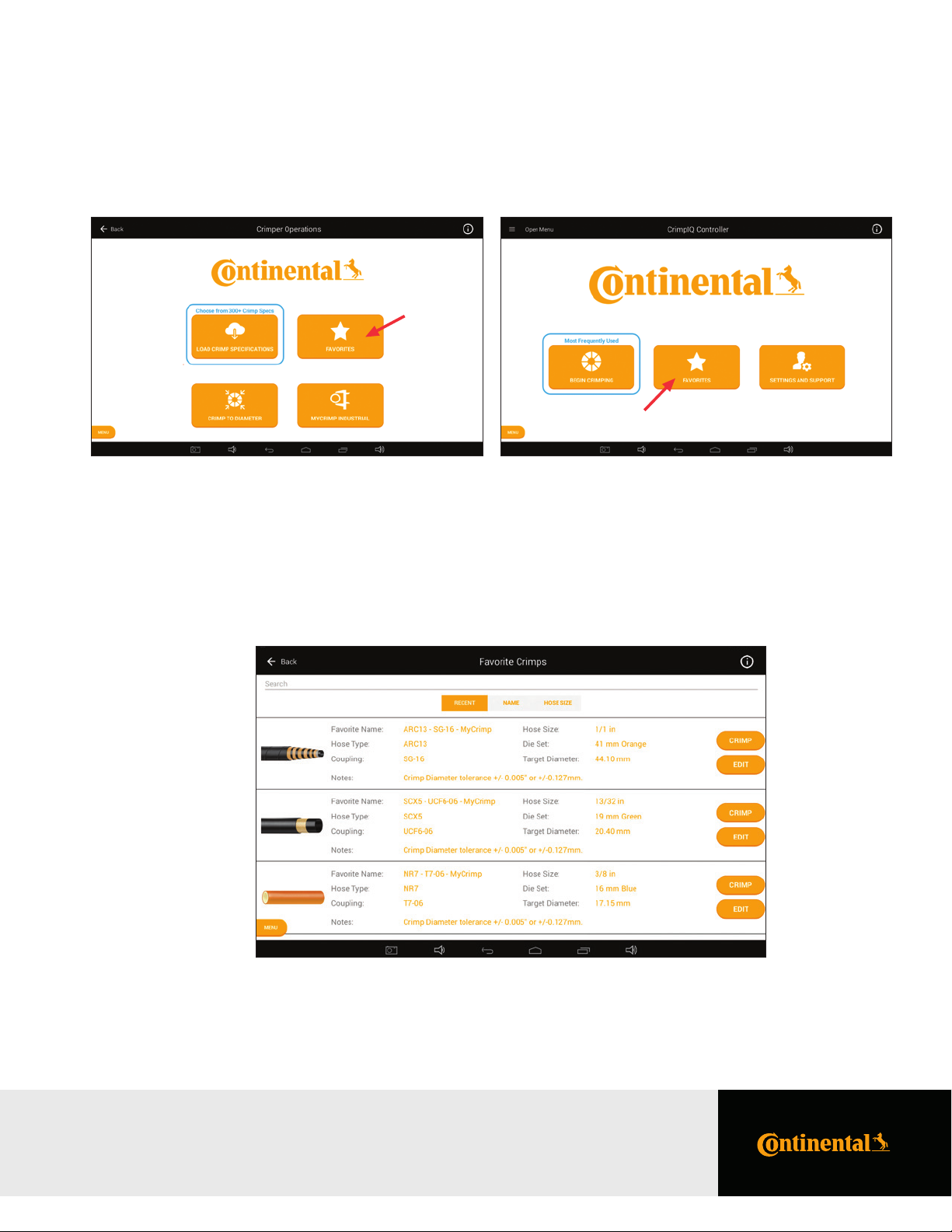
Favoriting Crimp Speciications
The user can save frequently crimped speciications for easy access and repeated crimping.
19PC440i Crimper – Operator Manual
This brings up a list of all the favorites saved on this machine. This scrollable list can be sorted by date added (Recent),
Favorite name (Name) or hose size.
Favoriting Crimp Speciications
PC440i Crimper with CrimpIQ™ Controller
Page 20

20 PC440i Crimper – O perator Manual
Editing a Favorite
Users have the option to edit the Favorite name and notes. You also have the option to delete favorites
that are no longer needed.
Favorite Special Handling
There are a subset of crimp speciications that require special handling. For these favorites, users must make an additional
check to verify that the correct crimp speciication has been selected. The system will automatically bring up a
“User Action Required” dialog and ask the user for an additional conirmation (or cancel).
Note: For these speciications, the edit function does not allow the note to be changed.
Favoriting Crimp Speciications
PC440i Crimper with CrimpIQ™ Controller
Page 21

Crimp to Diameter
If you already have the crimp speciication information, you can enter this directly and begin crimping. Simply choose the
Crimp to Diameter option from the Crimper Operations page.
Enter the appropriate crimp diameter target (in inches or mm). As you enter a target diameter, the crimp automatically
calculates the equivalent measurement in the other unit of measure.
The system will recommend a die and you can proceed to crimping.
21PC440i Crimper – O perator Manual
Note: If the keyboard is not visible, tap the Diameter data entry area and the keyboard will appear.
Crimp to Diameter
PC440i Crimper with CrimpIQ™ Controller
Page 22

22 PC440i Crimper – Operator Manual
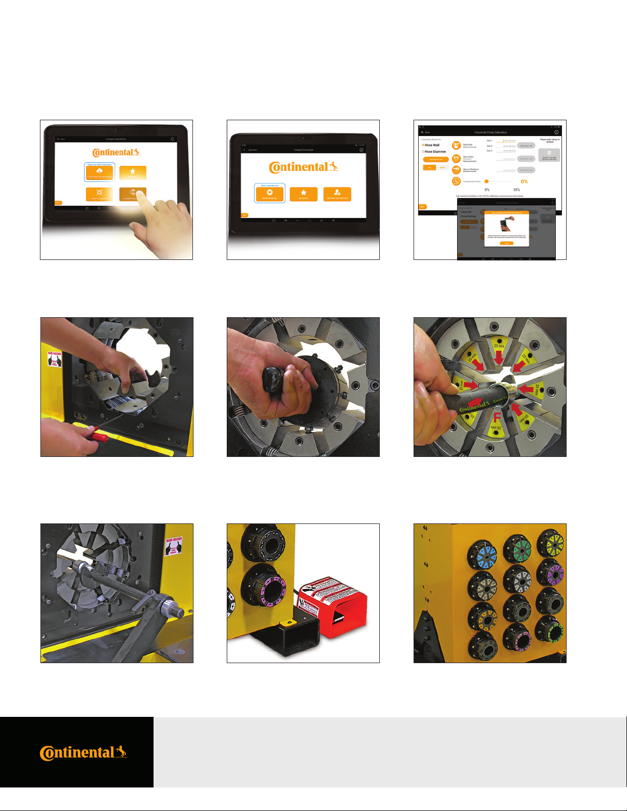
MyCrimp® Industrial Crimp Calculator
The Industrial Crimp Calculator allows users to enter information about the industrial hose, stem and sleeve,
along with a compression ratio. The calculator will then calculate the appropriate crimp diameter.
The calculator provides additional details on each required value. Press on the measurement icon and a more
detailed description pops up.
Entering Industrial Measurements
Hose Wall: Allows users to perform the calculation based on 3 measurements (averaged)
of the hose wall thickness.
Hose Diameter: A single hose diameter measurement.
Stem Outer Diameter: The diameter of the stem.
MyCrimp® Industrial Crimp Calculator
PC440i Crimper with CrimpIQ™ Controller
Page 23

23PC440i Crimper – Operator Manual
Sleeve Thickness: The thickness of the sleeve.
Compression Ratio: Compression ratios are available from hose and itting manufacturers.
Ratios must be between 10% and 35%.
As data is entered, the calculator will determine the inal crimp diameter (users cannot proceed to crimping until all ields
have information entered).
Once the data is entered and the calculation complete, you can proceed to crimping.
MyCrimp® Industrial
PC440i Crimper with CrimpIQ™ Controller
Page 24

24 PC440i Crimper – Operator Manual
Beginning a Crimp
Loading Dies
Regardless of how the crimp speciication/crimper was set up, the irst step in crimping is to load the correct die into the crimper.
As part of the crimper coniguration, the dies available to this crimper have been conigured (see Managing Preset Dies
on page 37). This pre-determined list of dies allows the crimper to determine which die to recommend for each crimp.
Crimp speciications and favorited crimp specs all include a recommended die. If that die is conigured for this crimper, the
user is prompted to install the recommended die.
Notes:
• Continental dies use color coding to help the user select the correct die set.
• The crimper will always prompt the user to “Install/Conirm” that the die is loaded. Therefore, even if the recommended
die is already loaded, the user will always be prompted to conirm that the correct die is installed in the crimper.
• While on the Change Die screen, the pump is on and the Open/Close button is enabled. The user can move the crimp
head as required to install the dies.
• In rare situations, the user may need to override the recommended die. This can be done by pressing the Die Options button.
This will bring up the list of available dies (described below).
• Caution: In Change Die mode, the crimper head will close to the die diameter.
Beginning a Crimp
PC440i Crimper with CrimpIQ™ Controller
Page 25

Selecting a Die
If a non-recommended die or no die is set, the controller will prompt the user with a list of conigured dies. The CrimpIQ™
controller will recommend a die that can crimp the required crimp diameter.
Once a die is selected, the machine will prompt the user to conirm/install the die in Change Die mode (described above).
25PC440i Crimper – Operator Manual
Notes:
• Dies that are grayed out are excluded because they are not capable of reaching the crimp diameter.
• This list is scrollable. You can slide the list up and down but, in general, the list will be centered on the dies that can be used
for this crimp.
• This list is limited to the dies conigured when the initial machine setup was completed
(either in the factory or during the initial machine setup).
• If you have a die appropriate for this crimp but it is not in the list of dies, you can manually
enter this die by choosing the Enter Manual Die option on the bottom right.
• If the selected die cannot crimp to the required crimp diameter, the crimper will display a warning.
Beginning a Crimp
PC440i Crimper with CrimpIQ™ Controller
Page 26

26 PC440i Crimper – Operator Manual
Change Die Mode
When you select the die, the pump will start and the Open/Close buttons will work to allow you to load the die in the crimper.
Once the die has been loaded, press the OK to continue.
Note: If the desired die is already loaded, simply press OK to continue.
Beginning a Crimp
PC440i Crimper with CrimpIQ™ Controller
Page 27

Crimp Operations
Performing the First Crimp
The irst crimp always needs to be measured to ensure the crimp is within tolerance of the crimp diameter.
Note: Once the calibration crimp has been completed and an initial crimp diameter entered (manually entered
or entered via USB CrimpIQ™ calipers), the crimper will automatically adjust to accurately crimp subsequent crimps.
27PC440i Crimper – Operator Manual
Crimp Operations
PC440i Crimper with CrimpIQ™ Controller
Page 28

28 PC440i Crimper – Operator Manual
Measuring a Crimp
The crimper will always prompt the user to measure the irst crimp. The crimper uses this measurement to adjust the
crimper to correctly crimp the next crimps.
When prompted, enter the measured crimp diameter. Measurements can be entered in inches or mm (the cursor will be
placed in either ield based on the preferred units of measure setup in the machine coniguration).
Notes:
• If the crimp diameter measurement matches the current crimp target, the user can press the Crimped to Target button to
automatically enter the measurement with a single button press.
• If a value is incorrectly entered, simply press the clear button.
• Once the measurement has been entered, the Save button is enabled and saves the measured crimp diameter for quality
assurance reporting.
• A keyboard will pop up on the bottom of the screen to allow users to enter crimp diameter data.
• If calipers are connected to the crimper, measurements can automatically be transferred into the measurement ield.
• The preferred units of measure are set up per user and can be conigured in the machine settings.
Crimp Operations
PC440i Crimper with CrimpIQ™ Controller
Page 29

Crimp Operations Screen
This screen provides the main controls for operating the crimper. While on this screen, the pump is running and the
Open/Close buttons are enabled (limited by Crimp Mode).
Crimp Operations Screen Sections
The operations screen is divided into 5 sections: Operations Information, Crimp Detail Panel, Crimp Mode, Crimp Settings
and Crimp Management.
29PC440i Crimper – Operator Manual
Operations Information
Crimp Mode Crimp Settings Crimp Management
Crimp Detail Panel
Crimp Operations
PC440i Crimper with CrimpIQ™ Controller
Page 30

30 PC440i Crimper – Operator Manual
Operational Information
Die Name: The name of the die that is currently installed in the machine.
Target Diameter: The diameter the machine is set to crimp to.
Current Position: Current die opening in inches and millimeters.
Crimp Detail Panel
This area of the screen provides the user with additional information about the crimping processes. The data in this area
rotates through a series of screens with dierent information. Users can cycle through each view with the icon in the
lower right section of this screen area.
Last 10 Diameters: A list of the last 10 crimp diameters
measured/entered into the CrimpIQ™ controller.
Note: The most recent is noted with a “*”
Last 10 Pressures: The last 10 maximum crimping
pressures measured in PSI.
Note: The most recent is noted with a “*”
Combined View: This view combines the measurement and the max pressure view into one.
Note: Users may not be required to measure every crimp.
Cycle Through Views
Crimp Operations
PC440i Crimper with CrimpIQ™ Controller
Page 31

Crimp Spec: Hose, itting and hose size information when loading a MyCrimp® speciication.
Hose Image: If a hose image is available, this image will be displayed.
31PC440i Crimper – Operator Manual
Spec Notes: This view shows the crimp speciications notes.
Industrial Crimp: This view summarizes the values entered into the Industrial Crimp Calculator.
Crimp Operations
PC440i Crimper with CrimpIQ™ Controller
Page 32

32 PC440i Crimper – Operator Manual
Crimp Mode
The crimper can operate in any of 3 dierent modes:
Manual Mode: Use this mode to manually Open/Close the head. Holding the Close button will close the head to
the target position and no further.
Semi-Automatic This mode allows the user to manually close the head to the target position. Once the crimper
Mode: reaches the target position, the crimper will automatically open back to the retraction point.
Full Automatic This mode allows the crimper to complete a complete cycle (close then open) with just a single
Mode: push of the close button. Once the hose and itting are correctly positioned, press the close button
once and the crimper will close to the target position and then automatically open back to the
retraction point.
Note: In either of the automatic modes, the foot pedal can also be used in place of the Close button.
Crimp Operations
PC440i Crimper with CrimpIQ™ Controller
Page 33

Crimp Information
33PC440i Crimper – Operator Manual
The Crimp Settings section contains status information and also a number of conigurable settings that the user
can change to adjust the crimp run.
Note: Each of these information areas can be conigured by pressing the icon to the left of the information.
Favorite: If this crimp speciication has been saved as a favorite, the name of the favorite will
be displayed here. To save a new favorite, simply press the favorite icon on the left.
PSI Monitoring/ The CrimpIQ™ controller has the option to monitor the crimping pressure and alert the user if the
Max PSI: PSI is out of range. Press the PSI icon to conigure the target PSI and tolerance.
Crimp Count: The CrimpIQ™ controller keeps track of the crimps completed. By default, this count goes up but
you can also set it to count down. This is conigured using the count icon on the left.
Users also have the option to “bump” the count up or down if needed.
Quality Mode: Quality mode automatically stops the crimping process after a speciied number of crimps and
prompts the user to measure the crimp diameter.
Crimp Operations
PC440i Crimper with CrimpIQ™ Controller
Page 34

34 PC440i Crimper – Operator Manual
Crimp Management Function Buttons
This section provides buttons to conigure and operate the crimper.
Measure/Adjust Crimp: This button allows the user to measure and record the crimp diameter. When activated, the
user can enter a crimp diameter measurement.
Change Die Mode: This mode allows the user to change die.
Suspend Crimp: Suspend Crimp is intended to put the crimper in a safe mode when the user needs to step
away from the machine for a short time. While suspended, the pump is turned o and the
Open/Close buttons are disabled.
Done: This button should be used when the user has inished all crimps with these settings.
Crimp Operations
PC440i Crimper with CrimpIQ™ Controller
Page 35

Settings and Support
In addition to the basic crimping operations, the CrimpIQ™ controller oers a number of other capabilities.
These include:
Machine Coniguration: Crimp setup/coniguration page with all of the conigurable options of this device.
See Machine Coniguration below.
Support: Support page allows users to request support directly from the machine.
See the Support below.
Manufacturer Website: Access to all of the information on the Continental corporate website.
See the Manufacturer Website below.
Training Manuals: Direct access to setup, guides and training manuals for the machine and controller.
See Training Manuals below.
Machine Information: Informational pages that provide users with basic machine stats and
operational information.
35PC440i Crimper – Operator Manual
Settings and Support
PC440i Crimper with CrimpIQ™ Controller
Page 36

36 PC440i Crimper – Operator Manual
Machine Coniguration
The CrimpIQ™ controller has a number of coniguration options that allow the machine operation to be customized to
meet the needs of each installation.
Main coniguration functions are grouped into menu options at the top of the page. The rest of the coniguration screen
provides access to all the remaining coniguration settings.
Notes:
• The options available vary by user type. Operators have very limited options and Machine Owners
have access to all options.
• After making coniguration changes, the CrimpIQ™ controller will attempt to back these changes up to CrimpCloud®.
This backup requires an Internet connection to complete.
Machine Coniguration Options
Manage Preset Dies: Setup the dies that are available for crimping on this machine.
See Manage Preset Dies above.
Manage Users: Edit and setup machine users. See Manage Users above.
Self-Calibration: Check the crimper calibration. See Self-Calibration Mode above.
Maintenance Mode: List of maintenance tasks, schedules and due dates for machine maintenance.
See Maintenance Mode above.
Setup Internet: Conigure and verify a tablet Internet connection. See Setup Internet above.
Backup to CrimpCloud®: Backup CrimpIQ™ controller coniguration to CrimpCloud®.
See Backup to CrimpCloud® above.
General Coniguration: Other Coniguration settings. See General Coniguration above.
Settings and Support
PC440i Crimper with CrimpIQ™ Controller
Page 37

Managing Preset Dies
This screen provides a list of all of available dies for this crimper. Administrators can set each die to Not Purchased/Purchased to
allow the CrimpIQ™ controller to ilter the list of dies the user sees to only dies that are available with this machine.
Each die has a name, type, size in inches and size in mm. If there is also a color code associated with the die that is displayed.
Administrators also have the option to create additional dies. Select the “Create New Preset Die” button and setup additional dies.
37PC440i Crimper – Operator Manual
Settings and Support
PC440i Crimper with CrimpIQ™ Controller
Page 38

38 PC440i Crimper – Operator Manual
Managing Users
The crimper comes conigured with three user accounts but Administrators have the option to setup additional users.
Additional users can be useful to track what each user/admin is doing on the machine. Information on the default users is
available in the Key User Information.
This setup screen allow Administrators to create new users and edit existing users.
Edit User: User name, 4 digit passcode and user type can be changed with this menu.
This is where an Administrator would reset the pin for a user who has forgotten their pin.
Create New User: Enter the user name, 4 digit passcode and user type to create a new user.
The CrimpIQ™ controller has been conigured with multiple user types. Each type has dierent capabilities within the crimper.
The goal is to provide users with all the privileges they require to do their tasks but no more.
Machine Admin: This is the highest privilege user type that can be conigured. This user type can change all machine
settings, access all support information and perform all crimp operations.
Machine Tech: This type has privileges to maintain the machine but cannot perform crimping tasks.
Supervisor: This type has privileges to monitor machine operations but cannot perform maintenance tasks.
Machine User: This type has privileges to use the machine, perform all crimping related tasks and has limited ability
to change machine coniguration.
Self-Calibration Mode
Self-calibration is a built-in test that veriies the accuracy of the crimper is within tolerance of its initial factory setup. If the test
fails (out of tolerance), a warning message is displayed showing the dierence from its initial set point.
To run the test, follow the instructions on the screen. At a high level, the test lows as follows:
• Load dies into the crimper (any standard hydraulic dies work). Make sure the crimp head is at least 1/3 open.
• Begin the self-calibration mode. This will prompt the user the press the Close button. The test then runs
automatically and returns a success/failure result.
Default User Accounts
To learn more about Default User Accounts, refer to page 10.
Settings and Support
PC440i Crimper with CrimpIQ™ Controller
Page 39

Maintenance Mode
This machine keeps track of a number of dierent periodic maintenance tasks. Tasks are based on machine model.
Maintenance tasks are either triggered by the number of crimps or the number of days since the last maintenance.
Tasks include: Check Hydraulic Oil, Grease the Crimper, Perform Self Calibration and Data Synchronization. Most of these are
self-explanatory with the exception of Data Synchronization (update crimp speciication, check for application updates and
sync data with the CrimpCloud®).
39PC440i Crimper – Operator Manual
Notes:
• When a maintenance event is triggered (by crimp count or date), the user gets a popup indicating that the maintenance
needs to be performed. To limit interference with operations, tasks can be delayed until a later date (Snoozed).
• Maintenance tasks are either triggered by the number of crimps or the number of days since the last maintenance, based
on the requirements of the task.
• Users can come to this Maintenance Mode screen and perform maintenance tasks or wait for the popup alert.
• Recording a maintenance task provides the user with an opportunity to add notes. The logged in user and date/time are
recorded along with the maintenance task.
• A complete history of maintenance performed is also available via the History button on the Maintenance Mode screen.
Setting Up an Internet Connection
This process allows users to conigure/verify Internet connections. An Internet connection is not required for day-to-day
operation but is beneicial. This section describes how to conigure dierent types of Internet connections and verify these
connections are working.
Using an Ethernet Connection
Plug the Ethernet cable into the base of the controller. The tablet will take a few moments to conigure the connection.
Once successful, the connectivity status will turn green.
Settings and Support
PC440i Crimper with CrimpIQ™ Controller
Page 40

40 PC440i Crimper – Operator Manual
Using a Wi-Fi Connection
Initiating the Wi-Fi setup process brings the user to the standard Android Wi-Fi setup screens. Choose the appropriate
Wi-Fi Network, enter in any required credentials and connect.
When the connection has been established, use the return arrow to return to the CrimpIQ™ controller application.
Connecting to a Captive Portal
Some customer locations have restrictions on which machines can connect to the company’s internal network. If this is the case,
see the additional connection options section below.
Verifying Connection Status
When the Internet connection has been successfully established, the connection status will change to a green check mark.
Please verify the connection before moving on to the next step.
Settings and Support
PC440i Crimper with CrimpIQ™ Controller
Page 41

Testing Proper Connectivity
You can use the “Verify Connection” button to verify that the crimper can reach the Internet. Users should see the
ContiFluidSolutions home page. If you don’t see this page, please contact your network administrator to enable access
from the CrimpIQ™ controller to the Internet.
Once the CrimpIQ™ controller is connected to the Internet, use the back button to go back to the setup process and then
continue to the next step by pressing the arrow in the bottom right of the screen.
41PC440 i Crimper – Operator Manual
Additional Connection Options
In some cases, network administrators may restrict which machines can access the company network.
There are 2 alternative connection options to complete the Crimp setup process:
1. Temporarily connect to a guest network:
The controller supports connecting to guest networks to complete the installation. The CrimpIQ™ controller needs an
Internet connection but does not require access to any internal company resources. A guest network can be used to
complete the setup and update processes for the controller. Simply enter the guest network credentials and the setup
can continue.
a. Enter the guest Wi-Fi credentials (via the Android Wi-Fi setup screens) and verify the connection is active (as described
above). The setup process only takes a few minutes after which the Wi-Fi connection is not needed.
b. Some facilities Wi-Fi connection use a web page to request user Wi-Fi login credentials. The controller supports this.
After selecting the appropriate network, return to the CrimpIQ™ controller setup screen. Use the verify connection
option to bring up the ContiFluidSolutions home page. The local network will then prompt for the required credentials.
2. Connect with a hot spot from a mobile device:
In some cases, network administration policies will not allow the CrimpIQ™ controller to access any network.
In that case, users must setup a Wi-Fi hotspot and use this connection to complete the setup process.
Internet Access Requirements
The CrimpIQ™ controller was designed to work with or without a dedicated Internet connection. If a dedicated connection
is not available, all of the essential crimping functions will work. The Internet associated features (ContiFluidSolutions home
page, support tickets, reporting) will not work because they require an active Internet connection to operation. Periodically, users
will be prompted to connect to the Internet to allow the CrimpIQ™ controller to sync information with CrimpCloud®. This sync
ensures the crimper has the latest software, crimp speciications and updates. It also ensures the machine coniguration
and operational history is backed up to CrimpCloud®. Operational information is used to generate reports and other
features available to users from CrimpCloud®.
Settings and Support
PC440i Crimper with CrimpIQ™ Controller
Page 42

42 PC440i Crimper – Operator Manual
Backup to CrimpCloud®
CrimpCloud® has the ability to provide reports on crimper operation and maintenance. In addition, it stores the coniguration
of the CrimpIQ™ controller (users, dies, favorites). Saving this coniguration allows Continental to replace the controller tablet,
pre-loaded, with all the backed up coniguration. Simply press “Backup to CrimpCloud” and the backup is performed.
General Coniguration
The following is a collection of other settings available to Administrators to conigure the CrimpIQ™ crimper
to meet their speciic needs.
User Settings - Preferred Units: Each user can have own settings for default units. Default units determine which
data entry ield the cursor is placed in.
Update Machine Registration: The Machine registration information provides the Continental support team with
location and contact information used to support the crimper.
Settings and Support
PC440i Crimper with CrimpIQ™ Controller
Page 43

Check Internet This feature is used to verify the Internet connection. A green check mark indicates a
successful network connection via Ethernet or Wi-Fi. A red exclamation point (!) indicates
there is no network connection. There are circumstances where the Wi-Fi signal is present
but the tablet still cannot access the Internet. To conirm the connection to the Internet, the
“Verify Connection” brings up the ContiFluidSolutions home page in a web browser. If the
site comes up, the CrimpIQ™ controller has a connection to the Internet.
Change Local Time Zone: Output ield to let Administrators know which time zone the tablet is set to. This information
is important for logging and reporting. This can be changed by selecting the correct time
zone from the drop down list.
Dual Pump: Larger crimpers has a dual pump coniguration to improve the speed of operation.
Slow Start Oset (mm): This setting indicates how far above the target crimp the pump/crimper switches from fast
to full power crimping mode.
Note: The default value generally does not need to be changed.
User Timeout Length: Length of time idle (in minutes) before the machine automatically locks and
requires a pin to login.
Note: This feature has an option to turn o (disables user timeout).
43PC440i Crimper – Operator Manual
Die Selection Tolerance: This setting helps the crimper recommend the best die for each crimp. This tolerance value
ensures that the crimper does not recommend a die that is too close to the target crimp
diameter that cannot crimp to the required diameter.
Note: The default value generally does not need to be changed.
Pressure Compensation On/O for Pressure Compensation. Pressure compensation uses the crimp pressure as
Mode: feedback to improve the accuracy of the irst crimp.
Note: Turning this feature on or o impacts the behavior of the irst crimp in crimp operations. It turns the
calibration crimp screen on or o, respectively.
Screen Brightness: Adjust the screen brightness for best viewing.
Enable Crimp Target On/O for a popup letting the user know that the crimper has successfully
Reached Popup: reached the target.
Enable Crimp Target On/O for a sound letting the user know that the crimper has successfully
Reached Beep: reached the target.
Settings and Support
PC440i Crimper with CrimpIQ™ Controller
Page 44

44 PC440i Crimper – Operator Manual
Require Measurement On/O setting for measurement popup on the initial crimp. Continental recommends
After 1st Crimp: that users ALWAYS measure the initial hydraulic crimp to ensure that the crimp
target is being reached (within tolerance). Turning this setting on always causes the
crimper to trigger the measurement popup on the initial crimp.
Connect Bluetooth Calipers: Coniguration and support to setup Bluetooth connected calipers.
Check for Update to CrimpIQ™ Trigger the CrimpIQ™ controller to connect to CrimpCloud® and check for
Controller: application updates. If found, the controller will download and install the latest
version of the application.
Note: Internet connection is required.
Check for Update to MyCrimp®: Trigger the CrimpIQ™ controller to connect to CrimpCloud® and check for
MyCrimp® application updates. If found, the controller will download and install the
latest version of the MyCrimp® application.
Note: Internet connection is required.
Force CrimpCloud® Operation Trigger the CrimpIQ™ controller to upload all operational data to CrimpCloud®.
Sync:
Note: In general, Administrators should not need to manually sync data. The controller will automatically sync data to
CrimpCloud® when appropriate.
Product Information – Email Provides a way for the Administrator to view the Terms of Service and if
Terms of Service: required, email them to the main contact for this machine.
View Source Attribution: Provides information on open source software incorporated into
the CrimpIQ™ controller.
Settings and Support
PC440i Crimper with CrimpIQ™ Controller
Page 45

Support
The application provides the user with a Technical Support system. This system allows the user to create a support ticket from
within the app. The support ticket and machine status information are automatically uploaded to the Continental support sta.
Note: The system must be connected to the Internet for this function to work.
45PC440i Crimper – Operator Manual
The user should create a ticket to get support:
Create a Ticket: This option allows the user to enter text to describe their issue. They can attach an image (using the
camera button on the bottom menu bar to capture the screen where the error is encountered).
Once submitted, this information is sent to CMS technical support sta for review and resolution.
Note: The machine must have Internet access to use this function.
Support
PC440i Crimper with CrimpIQ™ Controller
Page 46

46 PC440i Crimper – Operator Manual
Create a Ticket
To create a ticket, follow these steps:
1) Enter your email address: It is very important that this is entered correctly to ensure the support team can
quickly respond directly to the person having the issue.
2) Describe your problem: Enter a detailed description of the issue you are encountering so that the support
team can quickly provide support.
3) Attach an image: The CrimpIQ™ controller allows users to capture an image of
any screen (using the camera button in the bottom row of icons).
Images can be attached by pressing the paperclip icon in the
upper right corner of the screen.
4) Add images and text: You can attach multiple images to the ticket and add text to explain your issue.
5) Complete the process: To complete the process and send the support ticket, press the arrow icon in the upper
right section of the screen.
What Happens Next?
Once you submit the ticket, the information you entered (along with machine status and diagnostics) are sent to the
Tech Support team. The team will review your ticket along with the diagnostic information and respond back to the
email address provided.
The system will also send you a copy with a link to allow users to follow up on status or with additional information.
Support
PC440i Crimper with CrimpIQ™ Controller
Page 47

Conti Fluid Solutions
This option provides users with access to the Conti Fluid Solutions distributor site which includes tools, literature and services.
47PC440i Crimper – Operator Manual
Training Manuals
The controller provides access to a number of dierent training manuals.
The page lists a number of support resources available to machine users. These iles are downloaded as requested from
the Internet (Internet connection required).
Machine Information
The Machine Information screen provides operations and administrators with access to a range of operational and
machine information.
Support
PC440i Crimper with CrimpIQ™ Controller
Page 48

48 PC440i Crimper – Operator Manual
Other Topics
Integrated Caliper Measurements
The CrimpIQ™ controller supports direct integration of measurements (Crimp Diameter).
This integration saves time and reduces the chance that measurements are incorrectly entered.
Coniguring CrimpIQ™ Calipers (Bluetooth)
The CrimpIQ™ controller supports Bluetooth calipers to input crimp diameter measurements.
Setting up bluetooth calipers:
• Insert the Bluetooth dongle into the top of the calipers after removing the connection
cover. The “SMART” label should be facing toward the display screen.
• Tap the Bluetooth cell to see the list of Bluetooth devices, toggle to turn Bluetooth ON.
• Tap the toggle in the Bluetooth cell to turn Bluetooth ON.
• Hold the button on the Bluetooth module until the blue light starts blinking.
• The calipers should appear in the list of Bluetooth devices as “Bluetooth Keyboard” in
the list of AVAILABLE DEVICES.
• Select “Bluetooth Keyboard” from the list of devices to pair. If you don’t see this, turn
Bluetooth o and then on.
• The “Bluetooth Keyboard” should say Pairing while it is pairing with the tablet and
moved to list of PAIRED DEVICES once it is paired. The iGaging® dongle will also beep
when pairing is complete.
• Select the appropriate units (in./mm).
• Make sure the units match the default units in the crimper settings menu
(Main Menu → Crimper Settings → Select Preferred Unit of Measurement).
• When saving measurements from the calipers to the tablet there is a slight delay.
This is due to the power saving mode of the iGaging® dongle. Please give the transfer a
few seconds to complete.
Coniguring CrimpIQ™ Calipers (USB)
The CrimpIQ™ controller supports USB calipers to input crimp diameter measures.
Setting Up USB Calipers
• Insert the USB cable into the top of the calipers after removing the connection cover.
The “DATA” label should be facing toward the display screen.
• Plug the other end of the cable (standard USB Connection), into the USB connection
on the front of the controller box.
• Turn on the calipers.
• Select the appropriate units (in./mm).
• Make sure the units match the default units in the crimper settings menu
(Main Menu → Crimper Settings → Select Preferred Unit of Measurement).
Other Topics
PC440i Crimper with CrimpIQ™ Controller
Page 49

Using CrimpIQ™ Calipers
49PC440i Crimper – Operator Manual
Once the calipers are connected to the controller, they can be used to enter measurements within the CrimpIQ™ controller screens.
• The calipers are now ready to use. Whenever a measurement is required (Measure/Adjust Crimp in Crimper Operations
screen), the caliper’s measurement can be directly entered into the text box. Simply place the cursor in the correct ield and
press the DATA button on the calipers. Whatever value is displayed on the caliper display will automatically be transferred into
the controller.
• If calipers are connected to the controller, number entry keypads do not always appear. Simply press in the data entry ield and
a keypad will appear. For example, if changing users with the USB calipers connected, no keypad will appear to allow the user to
enter a pin. Simply press once in the entry ield and a keypad will pop up.
Other Topics
PC440i Crimper with CrimpIQ™ Controller
Page 50

50 PC440i Crimper – Operator Manual
PC440i Lubrication Procedure
Flush Fitting Adapter
Photo #1
Notes:
• Use the mini grease gun with flush fitting adapter with grease
(supplied with the crimper) or a high-pressure moly grade grease
can be used as well.
• Failure to lubricate the crimper can cause premature failure,
loss of accuracy and may result in damage to the crimper.
• Lubricate the crimping head after each 400 crimping cycles
or at the start of each shift if the crimper is used in a
production setting.
To begin, irst bring the master dies to the fully opened position,
and lubricate the ittings visible through the 2 bottom lubrication
ittings in the protective plate (as shown in photo #1).
Next, bring the master dies to the fully closed position, and lubricate
the master dies through the 8 lubrication ittings in the protective
plates (as shown in photo #2).
With the master dies still in the fully closed position, lubricate the
(4) lubrication ittings on each side of the crimper
(as shown in photos #3 and #4).
Note: Parking the crimper in the fully open position when it is not in use will
prolong the life of the master die springs.
Photo #2
Left Side
Photo #3
Right Side
Photo #4
PC440i Lubrication Procedure
PC440i Crimper with CrimpIQ™ Controller
Page 51

PC440i Die Installation and Management
Adapter Die Installation
Notes:
• The 160 mm O.D. to 99 mm I.D. Adapter Dies are held in place by the die
locking pins (as shown in photo #1).
• The I.D. of the adapter dies must match the O.D. of the corresponding
hydraulic die or accurate crimps cannot be made.
To begin, irst bring the master dies to the fully opened position to have access to
the (8) master die locking studs (as shown in photo #2).
51PC440i Crimper – Operator Manual
Photo #1
Next, install the 160 mm O.D. to 99 mm I.D. Adapter Dies, each inger
individually (as shown in photo #3).
Note: The die size stamped on the face of the adapter dies
should face toward the operator.
Use the THandle Wrench provided with the crimper to tighten the
master die locking studs to secure the adapter dies
(as shown in photo #4).
Photo #2
Photo #3
Photo #4
PC440i Die Installation and Management
PC440i Crimper with CrimpIQ™ Controller
Page 52

52 PC440i Crimper – Operator Manual
Hydraulic Die Installation
Notes:
• With the 160 mm O.D. to 99 mm I.D. Adapter Dies installed, use the
Quick Change Tool to install the hydraulic dies.
• The I.D. of the adapter dies must match the O.D. of the corresponding
hydraulic die or accurate crimps cannot be made.
To begin, irst bring the crimper head to the fully opened position and install the
Hydraulic Dies with the quick change tool (as shown in photo #1).
Note: The die size stamped on the face of the hydraulic dies should face
toward the operator.
Align the studs of the Hydraulic Dies with the holes in the Adapter
Dies and, with the crimper in manual mode, SLOWLY close the crimper head
on the hydraulic die set (as shown in photo #2).
Next, bring the crimper head to the fully closed position (as shown
in photo #3).
Remove the quick change tool (as shown in photo #4).
Notes:
• The Hydraulic Dies may also be inserted manually with the crimper
head in the fully open position.
• For Hydraulic Die removal, place the crimper in manual mode and bring the
crimper head to a fully closed position. Insert the quick change tool and open
the crimper head, releasing the Hydraulic Dies from their spring retention holes.
Photo #1
Photo #2
Photo #3
Photo #4
PC440i Die Installation and Management
PC440i Crimper with CrimpIQ™ Controller
Page 53

PC440i PLC Reset Procedure
53PC440i Crimper – Operator Manual
The PLC (Programmable Logic Controller) requires a relatively constant source of electrical power. Power surges, outages or drops in power
can cause the PLC to lose its settings. This may result in missing or misplaced information on the controller screen.
Resetting the PLC to Its Original Settings
• Open the back electrical enclosure.
• Power up the crimper from the main power switch. The crimper must be powered on during the PLC reset procedure.
• Move the three-position toggle switch on front of the PLC right to the STOP position and then left to the RUN position.
• Return the toggle switch to the center TERM position.
• Cycle the main power o and back on.
• The PLC and the crimper should now operate normally.
• Close the electrical enclosure.
PC440i PLC Reset Procedure
PC440i Crimper with CrimpIQ™ Controller
Page 54

54 PC440i Crimper – Operator Manual
PC440i Troubleshooting
PROBLEM: THE CRIMPER WILL NOT RUN AT ALL:
• Check the EStop switch to be certain that is not depressed. A slight twist is required to release switch after
it has been depressed.
• The PLC (Programmable Logic Control) must be reset. See instructions on the previous page.
PROBLEM: THE CRIMPER RUNS BUT IS SLOW OR NONFUNCTIONAL:
• Check electrical circuit to be certain that it matches the crimper’s requirements shown on the voltage tag attached to the
crimper cord. Many performance problems are the result of low voltage or inadequate electrical service.
• Check motor rotation and be certain that the motor rotates in the direction of the arrow on the motor housing.
Note: For three-phase units, rotation can be reversed by switching any two wires in the plug.
PROBLEM: THE CRIMPER WILL CLOSE ON THE FITTING BUT DOES NOT DEVELOP
POWER TO COMPLETE THE CRIMP:
• Position the master dies to the fully opened position and check the hydraulic oil level in the sight glass window
on the front of the reservoir. Be sure that the oil level is in the middle of the sight glass window.
Note: Use ISO grade 46 hydraulic oil.
PROBLEM: THE CRIMPER WILL NOT OPEN TO RETRACT POSITION IN AUTO MODE:
• The retract position must be at least 3 mm larger than the inal crimp diameter.
If problems persist, contact Customer Service for additional troubleshooting assistance.
PC440i Troubleshooting
PC440i Crimper with CrimpIQ™ Controller
Page 55

PC440i Component Parts Breakdown
7
6
8
55PC440i Crimper – Operator Manual
9
PART NUMBERITEM
3
1
5
10
5
7
94846A0319
2
PC440i SHEET METAL ASSEMBLY
3/8-16 Hex Nut
QTYDESCRIPTION
1Front Panel Wrap1041461
1Rear Panel Wrap1041482
1Frame Top Panel Wrap1040983
1Access panel1046164
12Die Holder101242
112x12 Mirror9194T316
1CC440/CC600/1000 Mirror Attachment Bracket103345
4CC440/CC600/1000 Mirror Bracket Support Arms1033078
2
481/4-20 X 3/8 SHCS91251A53510
4
PC440i Component Parts Breakdown
PC440i Crimper with CrimpIQ™ Controller
Page 56

56 PC440i Crimper – Operator Manual
PC440i Component Parts Breakdown
PC440i SHEET METAL AND BACKSTOP ASSEMBLY
4
5
3
2
1
QTYDESCRIPTIONPART NUMBERITEM
245/16-18 X 1/2'' BHCS91255A5781
1Rear Access Panel1043102
1Backstop Mou nt1033913
1Backstop Bracket Assembly1037654
1Backstop Bracket Arm1033925
PC440i Component Parts Breakdown
PC440i Crimper with CrimpIQ™ Controller
Page 57

PC440i Component Parts Breakdown
57PC440i Crimper – Operator Manual
CC440 FRAME/LEG/POTENTIOMETER ASSEMBLY (104083-MAN)
91251A7945
7
91251A5808
20
17
18
22
12
14
13
15
19
21
16
1
91255A58314
10460917
10461018
91294A23620
10461121
5/8-11 X 1.00 SH CS
5/16-18 X 5/8 SHCS
5/16-18 X 1'' BHCS
Face Cover Plate (Top)
Face Side Plate Cover
M6 X 12mm FH CS
Face Plate Spacer
QTYDESCRIPTIONPART NUMBERITEM
1Frame/Master Die Assy1040821
2Leg Brace1041732
65/8-11 X 1.50 SH CS91251A7983
2Base Leg1040944
16
4 Leg Mounting Bracket1042276
1Transducer Mtg Bracket104267
6
1150MM Transducer1034729
4M4x0.7 Nyloc Hex Nut90576A10310
1Transducer Rod Bracket10426811
1Retraction S top10408412
1Limit Switch914CE1-613
2
210-24 X 7/8'' BHCS91255A24615
2Face Cover Plate (Bottom)10460816
2
4
8Metric Plain Washers22M - 6 N19
8
8
8M 6 X 20mm BHCS91294A24022
118
910
6
4
8
7
3
2
5
PC440i Component Parts Breakdown
PC440i Crimper with CrimpIQ™ Controller
5
Page 58

58 PC440i Crimper – Operator Manual
PC440i Component Parts Breakdown
4
7
PC440i MASTER DIE COVER PLATE ASSEMBLY
1046081
1046104
90850A1505
7
FACE COVER PLATE (BOTTOM)
FACE PLACE SIDE COVER
5/16 FLAT WASHER
2
6
4
3
1
QTYDESCRIPTIONPART NUMBERITEM
1
1FACE COVER PLATE (TOP)1046092
4FACE PLATE SPACER1046113
2
4
4M6 X 14mm FHCS91294A2376
4M6 X 20mm BHCS91239A326
5
PC440i Component Parts Breakdown
PC440i Crimper with CrimpIQ™ Controller
Page 59

PC440i Component Parts Breakdown
59PC440i Crimper – Operator Manual
2
4
11
7
1
8
9
11
3
CC 440 ELECTRICAL BOX ASSEMBLY (103759-CC440)
1023695
7
69915K5711
6
Contactor with Overload Protector
Cord Grip
5
10
QTYDESCRIPTIONPART NUMBERITEM
1Relay Block1023681
1Fuse Block1023672
2Ground Block1023653
1Power Supply1023714
1
2MIDGET 5 AMP FUSE HOLDERCHMD26
3Relay103782
1Relay102368-White Motor Block8
150 Amp Disconnect Switch1030509
23/4 NPT Cord Grip69915K5610
3
PC440i Component Parts Breakdown
PC440i Crimper with CrimpIQ™ Controller
Page 60

60 PC440i Crimper – Operator Manual
PC440i Component Parts Breakdown
PC440i Component Parts Breakdown
PC440i Crimper with CrimpIQ™ Controller
Page 61

PC440i Warranty
Should you experience diiculty with any product or part and require technical support, irst contact
Customer Service at 18002354625. This Continental branded crimper is manufactured especially for ContiTech
and is covered by the manufacturer under the below warranty.
CustomCrimp® “No Nonsense” Warranty
All CustomCrimp® products are warranted to be free of defects in workmanship and materials for one year from the date of invoice.
This warranty ends when the product becomes unusable for reasons other than defects in workmanship or material.
If any product or part manufactured by CustomCrimp® is found to be defective by CustomCrimp®, at its option CustomCrimp® will
either repair or replace the defective part or product and return via ground transportation, freight prepaid.
This warranty does not cover any product or part which is worn out, abused, altered, used for a purpose other than for which it was
intended or used in a manner which was inconsistent with any instructions regarding its use.
Electric motors are separately warranted by their manufacturer under the conditions stated in their separate warranty.
61PC440i Crimper – Operator Manual
PC440i Warranty
PC440i Crimper with CrimpIQ™ Controller
Page 62

Industrial Fluid Solutions
Market segment
Hydraulic Hose
Contact
Co nti Tech
703 S. Cleveland Massillon Road
Fairlawn, OH 443333023 U.S.A .
18 00235 4632
www.contitech.us
Your local contact
www.contitech.de/contactlocator
Canada
18882754397
Mexico
18004397373
ContiTech. Smart Solutions Beyond Rubber
The ContiTech division of the Continental Corporation
is one of the world’s leading industry specialists. As
a technology partner, our name is synonymous with
expertise in development and materials for components
made of natural rubber and plastics and also in
combination with other materials such as metal, fabrics
or silicone. By integrating electronic components, we are
also generating solutions for the future.
Beyond products, systems and services, we also provide
holistic solutions and have a formative inluence on the
industrial infrastructure. We see digitalization and current
trends as an opportunity to work with our customers to
add sustainable value – for both sides and for good.
The conte nt of this pu blication is not le gally binding an d is provided
as inform ation onl y. The tradem arks dis played in th is publication are
the property of Continen tal AG and/o r its a iliates. Copyri ght © 2018
ContiTech AG . All right s reserved. For com plete info rmation g o to:
www.contitech.de/discl_en
2103055210/18
 Loading...