

Continental Refrigerator IOF-240-B Maintenance Manual

IOF-240-B
CONTINENTAL® AIRCRAFT ENGINE
MAINTENANCE
MANUAL
TECHNICAL PORTIONS OF THIS MANUAL ARE FAA APPROVED
Publication M-22 Change 2
© 2007 TELEDYNE CONTINENTAL MOTORS INCORPORATED DEC 2007

TM
Teledyne Continental Motors, Inc.
Supersedure Notice
This manual is a revision of TCM IOF-240-B Maintenance Manual, M-22, dated July 2003. Instructions previously
referred to in the F-4 FADEC System Manual, dated July 2003, have been incorporated in this manual. This m an ual
supersedes both the M-22 and F-4 Manuals. Previo us versions are obsolete upon release of this manual.
Effective Changes for this Manual
0 ................................29 Nov 2006
1 ................................30 Aug 2007
2 ................................1 Dec 2007
List of Effective Pages
Document Title: IOF-240 Series Engine Maintenance Ma nual
Publication Number: M-22 Original Publication Date: 29 Nov 2006
Page ...................Change Page ...................Change Page................... Change Page................... Change
Cover – ii....................2 4-1 thru 4-2.................0 B-1 thru B-12..............1
iii-viii...........................0 5-1 thru 5-2.................0 C-1 thru C-20.............0
1-1 thru 1-3 ................0 6-1 thru 6-14...............1 C-21...........................1
1-4..............................1 7-1 thru 7-64...............1 C-22 ...........................0
1-5 thru 1-6 ................0 8-1 thru 8-44...............1
1-7 thru 1-9 ................1 9-1 thru 9-17...............0
1-10 ............................0 9-18 thru 9-22.............1
2-1 thru 2-21 ..............1 10-1 thru 10-6.............1
2-22 ............................2 10-7 thru 10-8.............0
2-23 thru 2-26 ............1 10-9 thru 10-15...........1
3-1 thru 3-11 ..............1 10-16 thru 10-43.........0
3-12 thru 3-16 ............0 10-44 thru 10-55.........1
3-17............................1 10-56 thru 10-57......... 0
3-18 thru 3-21 ............0 10-58 thru 10-59.........1
3-22 thru 3-23 ............1 10-60 thru 10-66.........0
3-24 thru 3-25 ............0 10-67 thru 10-69.........1
3-26............................1 10-70 thru 10-77......... 0
3-27 thru 3-29 ............0 10-78 thru 10-84.........1
3-30 ............................1 A-1 thru A-8................0
Published and printed in the U.S.A. by Teledyne Continental Motors.
Available exclusively from the publisher: P.O. Box 90, Mobile, AL 36601
Copyright © 2007 by Teledyne Continental Motors. All rights reserv ed. This materia l may not be re printed , repub lishe d, broadc as t, or oth erwise
altered without the publisher’s writte n permission. This manua l is provided without ex press, statutory, or implied warranties. The publisher will
not be held liable for any damages c aused by or alleged to b e caused by use, mis use, abuse, or misin terpretation of the cont ents. Content is
subject to change without notice. Other products and companies mentioned herein may be trademarks of the respective owners.
ii IOF-240 Series Engine Maintenance Manual
Change 2 1 December 2007

TM
Teledyne Continental Motors, Inc.
Service Document and Technical References
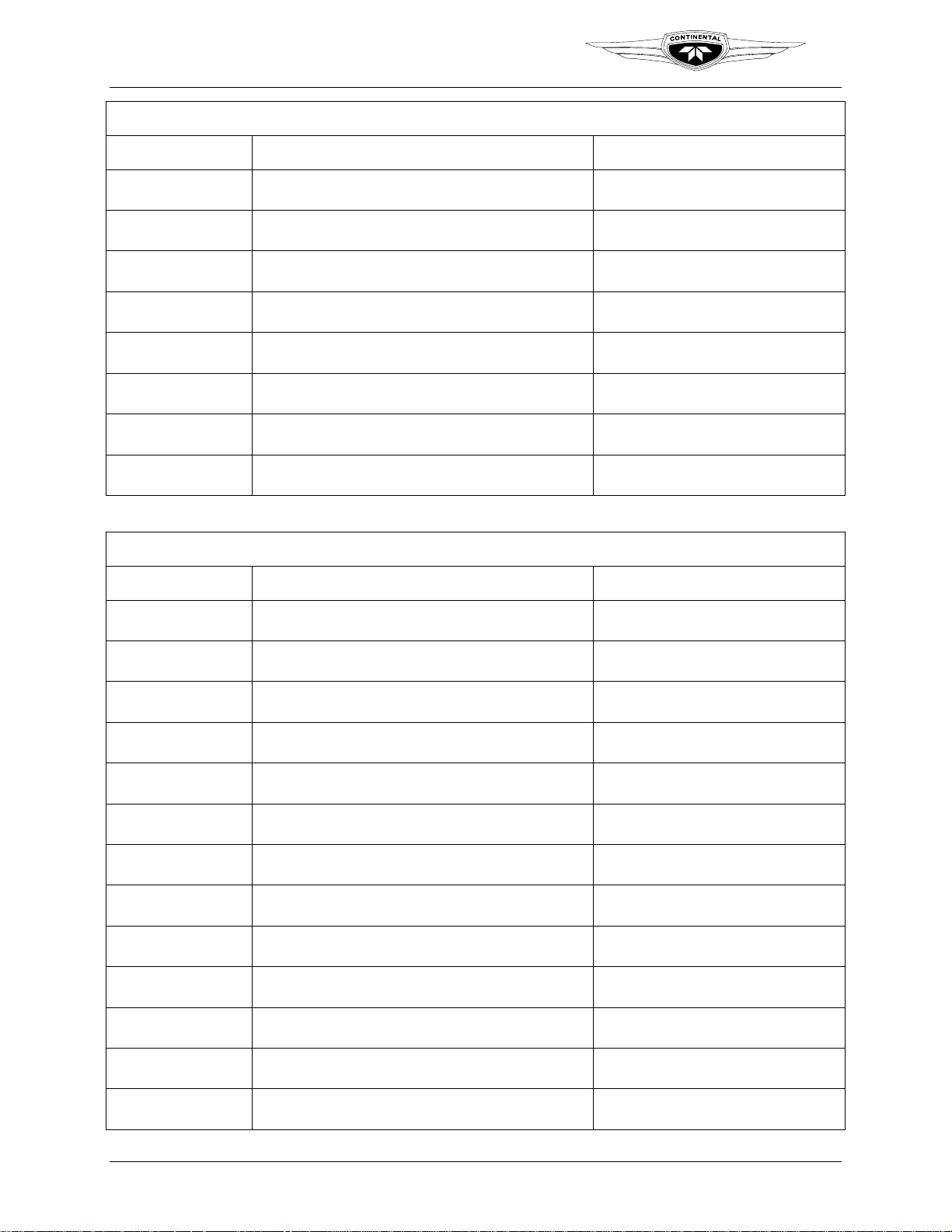
Service Documents and technical information cited in this edition of TCM’s Maintenance
Manual (M-22) are listed in the chart below. Information relevant to this engine series from these
Service Documents has been incorporated in this manual. The full content of all TCM and
supplier service documents is available on TCMLINK. Refer to the section “Publication Access”
in Chapter 1 of this manual for TCMLINK details.
Service Documents Incorporated in this Manual
Service Document Subject Section Affected
Chapter
MHS-24, Ashless Dispersant
Lubricating Oil
MHS-24, Appendix
MHS-27,“Engine Break-in and
Preservation Oil
M76-4, Installation of Propeller shaft
Oil specifications
Break-in and preservation
oil specifications
Oil seal replacement N/A N/A
Specifications and
Operating Limits
Chapter 2
Chapter 7
Chapter 9
Break-in Oil Chapter 2
Chapter 9
or nose oil seals
M87-15, Alternator Ground Strap Alternator Replacement N/A N/A
M88-9, Lightning Strikes
Unscheduled
Inspections Chapter 7
Maintenance
M88-10, Contaminated Fuels
Unscheduled
Inspections Chapter 7
Maintenance
M89-9, Excessive Crankcase
Pressure
M90-13, Exhaust Valve Stem
Unscheduled
Inspections Chapter 7
Maintenance
Inspection and Overhaul N/A N/A
Corrosion/Erosion
M91-9, Cam and Lifter Lubrication
Overhaul N/A N/A
during Rebuild
SIL93-11A, New Service Document
Format
Service Documents
Service Document
Categories
Chapter 1
SIL93-14, CFC Compliance N/A N/A N/A
SIL93-15, General Practices for
Standard Practices Standard Practices Appendix C
Installation of Lock Wire, Tab
Washers, and Cotter Pins
SIL94-5, Mobil AV-1 Oil Authorized Lubricants Authorized Lubricants
Engine Oil Servicing
CSB95-4, Intake Valve Guide Seal
N/A N/A N/A
Chapter 2
Chapter 9
Inspection
SB95-2, Inspection and Maintenance
Inspection Scheduled Inspections Chapter 7
of Engine Control Cables and
Linkage
SB95-3B, Alternator/Generator Drive
Inspection Inspection Chapter 7
Couplings
SB95-7, Manifold Valve Cover
Inspection Inspection Chapter 7
Inspection
IOF-240 Series Engine Maintenance Manual iii
29 November 2006

Teledyne Continental Motors, Inc.
Service Documents Incorporated in this Manual
Service Document Subject Section Affected
Chapter
TM
SIL95-5, Hose and Tubing Installation
Hose and tubing
Standard Practices Appendix C
installation
CSB96-1, Starter Gear and Clutch
N/A N/A N/A
Assembly, P/N 653575
SB96-7C, Torque Limits Specific torque values Torque Values Appendix B
SB96-11A, Propeller Strikes and
Hydraulic Lock
SB96-12, Continued Airworthiness for
TCM Cylinders
Inspections Propeller Strikes
Chapter 7
Hydraulic Lock
Inspections
Visual Inspection,
Chapter 7
Compression Check,
Leak Check,
SIL97-1, “Airworthiness Limitations Airworthiness Limitations Airworthiness Limitations Chapter 3
SID97-2B, TCM Cylinder Warranties N/A N/A N/A
SID97-4C, Cylinder Bore and Piston
Fit Specifications
M97-6, Mandatory Replacement
Service Limits
Inspection and Repair Various Throughout
Cylinder Removal and
Replacement
Chapter 10
Parts
CSB97-10A, Piston Pin Plug Wear Service Limits
Cylinder Removal and
Chapter 10
Replacement
CSB98-1B, Intake and Exhaust Valve
Inspection
Service Limits
Cylinder Removal and
Replacement
Chapter 10
SIL98-6B, Fuel Injection System
N/A N/A N/A
Application Guide
SIL98-9A, Time Between Overhaul
Periods
SIL99-1, Engine Preservation for
Active and Stored Aircraft
Engine Specifications,
Scheduled Maintenance
Engine preservation and
returning an engine to
Overhaul Periods Chapter 2
Chapter 7
Placing an Engine in
Chapter 10
Service After Storage
service after storage
SIL99-2B, Current Listing of
Sealants, Lubricants and Adhesives
Materials
Engine Operation in
Extreme Cold
Chapter 2
Chapter 6
Authorized by TCM
Chapter 7
Chapter 10
SB99-8, Engine Fuel Injection
System Preservation
SB00-4A, Australian AVGAS
Contamination
Fuel Injection system
Engine Installation Chapter 5
storage
Inspection and Operation Inspection Requirements Chapter 2
Chapter 7
SB00-10, Fuel Pump Seal Fuel Pump Installation Fuel Pump Installation Chapter 10
SIL00-7A, Oil Gauge Rod Application
Inspection and Oil
Engine Oil Servicing Chapter 9
Servicing
SIL00-9A, Engine Data Plates N/A N/A N/A
iv IOF-240 Series Engine Maintenance Manual
29 November 2006

TM
Teledyne Continental Motors, Inc.
Service Documents Incorporated in this Manual
Service Document Subject Section Affected
Chapter
SIL00-11B, Release of new Cylinder
Induction Port Drain Connector
SIL02-6A, Production Release of
optional intake and exhaust valves
SIL03-1, Cold Weather Operation –
Engine Preheating
SIL03-2, Currently Active Approved
Spark Plug Application
SIL03-3, Differential Pressure Test
and Borescope Inspection
SB04-4A, Manifold Valve Spring
Replacement
SB04-11, Valve Guide Application,
Installation and Reaming
SIL04-2, Cylinder Barrel Ultrasonic
Inspection
SIL04-12, TCM Authorized Engine
Adjustments, Component
Replacement and Repositioning
Cylinder Assembly Cylinder Assembly Chapter 10
N/A N/A N/A
Preheating procedures
Spark plugs
Inspection Criteria Inspection Chapter 7
N/A N/A N/A
N/A N/A N/A
N/A N/A N/A
Engine Specification
Engine Operation in
Extreme Cold and
subsections
Engine Specifications
and Operating Limits
Engine Specifications
and Operating Limits
Chapter 7
Chapter 2
Chapter 9
Chapter 2
SB05-2, Overspeed Limitations
SIL05-3, Engine Specification
Numbers
SIL06-4, FADEC Health Status
Annunciator Indications
Unscheduled
Maintenance
Engine Specification Engine Designation Chapter 2
Engine Operating
Characteristics
Inspections Chapter 7
N/A N/A
Service Bulletins Released After Publication
TCM strives to provide clear, concise, and accurate information and instructions based on best
known engineering data at the time of publication. Ongoing process improvements at TCM may
change a specification or procedure after a manual is released. Service Documents, defined in
Chapter 1, expedite customer notification and serve as the prevailing instruction over conflicting
information until the new information is incorporated in the manual text. Such bulletins are part
of TCM’s Instructions for Continued Airworthiness. As bulletins are received, note the bulletin
number, title, and applicable section affected by the bulletin in the blank cells below and insert a
copy of the Service Bulletin behind the last page of this section.
The following bulletins, released after this manual, affect and supplement the procedures herein.
When performing procedures affected by the bulletins, review the bulletin content prior to
commencing the task to ensure completion using the most current information and methods.
TCM recommends placing a note at the beginning of the affected section in the manual as a
reminder to review the service document.
IOF-240 Series Engine Maintenance Manual v
29 November 2006
TM
Mandatory and Critical Service Bulletins Published After this Manual
Document Number Title Affected Section(s) in this Manual
Teledyne Continental Motors, Inc.
Other Service Documents Published After This Manual
Document Number Title Affected Section(s) in this Manual
vi IOF-240 Series Engine Maintenance Manual
29 November 2006

TM
Teledyne Continental Motors, Inc.
PREFACE
Teledyne Continental Motors (TCM) provides Instructions for Continued Airworthiness based
on the design, testing, and certification of engines and parts for which TCM is the holder of the
Type Certificate (TC) or Parts Manufacturing Approval (PMA) issued by the Federal Aviation
Administration (FAA). Instructions in TCM manuals, which include maintenance, repair limits,
overhaul, and installation, are applicable only to engines and parts supplied by TCM.
This manual, the Installation and Operation manual and the Overhaul Manual, applicable service
documents, and other related publications constitute the Instructions for Continued
Airworthiness (ICAs) prepared by TCM and approved by the FAA. Pursuant to Federal Aviation
Regulation (FAR) § 43.13, each person performing maintenance, alteration, or preventive
maintenance on the engine or accessories must use methods, techniques, and practices prescribed
in the ICAs.
Except for FAR part 43.3 authorized owner maintenance, TCM ICAs are written for
exclusive use by FAA (or equivalent authority) licensed mechanics or FAA (or equivalent
authority) certified repair center employees working under the supervision of an FAA
licensed mechanic. Information and instructions contained in this manual anticipate the
user possesses and applies the knowledge, training, and experience commensurate with the
requirements to meet the prerequisite FAA license and certification requirements. No other
use is authorized.
Installation of non-TCM parts on a TCM engine constitutes a deviation from TCM type-design
criteria. TCM has not participated in design, test, or certification of any non-TCM parts. TCM
does not provide product manufacturing specifications to aftermarket parts manufacturers and
accepts no liability for the suitability, durability, longevity, or safety of such parts installed on
TCM engines. Installation of non-TCM parts on a TCM engine must be performed using
Instructions for Continued Airworthiness prepared by the manufacturer and approved by the
FAA for the subject installation. TCM ICAs must not be used for such parts.
Service documents may contain general information or information specific to a group of
engines or be in effect for a limited time frame. Service Documents may also contain advance
changes to the ICAs. It is the responsibility of the organization/person maintaining or operating
the engine to verify that current and complete information, including Service Bulletins, FAA
Airworthiness Directives (ADs), and publications are used.
To facilitate the use of current data, TCM provides information via the Internet on TCMLINK.
The information available includes a listing of the latest manual versions, service bulletins, FAA
ADs, and other information applicable to the ICAs. This information is free of charge to owners
of TCM engines by registering as an Aviator Service Member.
The latest manuals are available through TCMLINK to Fixed Base Operators (FBOs) who are
TCM FBO Services subscribers. Information available through Aviator Services is also available
through FBO Services. Hardcopies and service subscriptions are available from TCM. Refer to
“Publication Access” listed in Chapter 1.
IOF-240 Series Engine Maintenance Manual vii
29 November 2006

TM
Teledyne Continental Motors, Inc.
CONTENTS
Chapter 1 - Introduction............................................................................................................... 1-1
Chapter 2 - Engine Description.................................................................................................... 2-1
Chapter 3 - Special Tools and Supplies ....................................................................................... 3-1
Chapter 4 - Airworthiness Limitations ........................................................................................4-1
Chapter 5 - Engine Removal and Installation.............................................................................. 5-1
Chapter 6 - Operational Performance Tests................................................................................. 6-1
Chapter 7 - Maintenance Inspections........................................................................................... 7-1
Chapter 8 - Troubleshooting ........................................................................................................8-1
Chapter 9 - Maintenance and Adjustments.................................................................................. 9-1
Chapter 10 - Non-Overhaul Repair and Replacement ............................................................... 10-1
Appendix A - Glossary ............................................................................................................... A-1
Appendix B - Torque Specifications........................................................................................... B-1
Appendix C - Standard Practices ................................................................................................ C-1
OVERHAUL MANUAL (OH-22)
Chapter 1 - Introduction............................................................................................................... 1-1
Chapter 2 - Engine Description.................................................................................................... 2-1
Chapter 3 - Special Tools and Supplies ....................................................................................... 3-1
Chapter 4 - Airworthiness Limitations ........................................................................................4-1
Chapter 5 - Engine Removal and Installation.............................................................................. 5-1
Chapter 6 - Engine Disassembly..................................................................................................6-1
Chapter 7 - Component Disassembly ..........................................................................................7-1
Chapter 8 - Engine Cleaning........................................................................................................ 8-1
Chapter 9 - Overhaul Inspection and Repair................................................................................ 9-1
Chapter 10 - Component Assembly........................................................................................... 10-1
Chapter 11 - Engine Assembly .................................................................................................. 11-1
Chapter 12 - Post-Overhaul Testing ..........................................................................................12-1
Appendix A - Glossary ............................................................................................................... A-1
Appendix B - Torque Specifications........................................................................................... B-1
Appendix C - Standard Practices ................................................................................................ C-1
viii IOF-240 Series Engine Maintenance Manual
29 November 2006

TM
Teledyne Continental Motors, Inc.
Introduction
Chapter 1. INTRODUCTION
CONTENTS
Chapter 1. Introduction.............................................................................................................1-1
1-1. Scope and Purpose of This Manual......................................................................................1-2
1-1.1. Advisories.................................................................................................................................................. 1-3
1-1.2. Using this Manual...................................................................................................................................... 1-3
1-1.3. Compliance................................................................................................................................................ 1-4
1-1.4. Order of Precedence..................................................................................................................................1-5
1-2. Publications ..........................................................................................................................1-6
1-2.1. Service Documents.................................................................................................................................... 1-6
1-2.2. Related Publications..................................................................................................................................1-7
1-2.3. Publication Access..................................................................................................................................... 1-8
1-2.4. Publication Changes..................................................................................................................................1-8
1-3. TCM Contact Information....................................................................................................1-9
LIST OF TABLES
Table 1-1. Related Publications...................................................................................................1-7
IOF-240 Series Engine Maintenance Manual 1-1
29 November 2006

Introduction
1-1. Scope and Purpose of This Manual
This manual provides instructions for installing and operating IOF-240 aircraft engines,
equipped with Full Authority Digital Engine Control (FADEC), manufactured by
Teledyne Continental Motors (TCM).
Instructions in this manual are specific to IOF-240 engines. For information specific to
other TCM engine series, accessories, or the airplane, refer to the appropriate manual.
Chapters are arranged in sequential order to install, test, and operate the engine.
This Maintenance Manual (M-22) is supplemented by the TCM Installation and
Operation Manual (OI-22) and Overhaul Manual (OH-22). Procedures in the OI-22
provide instructions for installing a new TCM engine in an airframe at a Fixed-Base
Operator location. The OI-22 supplements the Pilot’s Operating Handbook with enginespecific technical information and instructions.
This manual, along with the overhaul manual provides complete maintenance and
overhaul information for the engine series. This manual provides general maintenance
information including maintenance schedules, inspection and service requirements,
troubleshooting and repair procedures. The overhaul manual provides detailed engine
overhaul instructions to return the engine to like-new specifications.
The maintenance section begins with administrative instructions regarding access to
TCM publications and a list of other manuals that will enable the mechanic to perform
the procedures required to maintain the engine’s airworthiness. Chapter 2 contains a
detailed engine description including engine specifications and operating limits. Chapter
3 lists special tool and supply requirements as well as vendor contact information.
Chapter 4 contains FAA airworthiness limitations. Chapter 5 provides engine removal
and installation instructions. Chapter 6 contains instructions to verify the engines
serviceability after maintenance or overhaul. Chapter 7 provides maintenance and
inspection scheduling as well as unscheduled maintenance and the associated procedures
to accomplish those tasks. Chapter 8 contains troubleshooting procedures and suggested
corrective actions. Chapter 9 contains maintenance and adjustment procedures. Chapter
10 contains non-overhaul repair and replacement procedures, referred to as “heavy
repair.”
The overhaul manual is arranged in the sequential order of tasks required to complete the
overhaul process. Overhaul instructions include disassembly, cleaning and inspection
requirements to determine which parts are suitable for overhaul. Overhaul instructions
also include required replacement items and detailed part refurbishing procedures.
Finally, instructions are provided for detailed engine assembly and post overhaul testing.
Appendix A in this manual provides acronym definitions and a glossary of common
terms used in the manual. Appendix B lists fastener torque specifications; Appendix C
contains procedures and illustrations for standard practices.
TM
Teledyne Continental Motors, Inc.
1-2 IOF-240 Series Engine Maintenance Manual
29 November 2006

TM
Teledyne Continental Motors, Inc.
1-1.1. Advisories
This manual utilizes three types of advisories; defined as follows:
A warning emphasizes information which, if disregarded,
could result in severe injury to personnel or equipment failure.
CAUTION: Emphasizes certain information or instructions, which if
disregarded, may result in damage to the engine or accessories.
NOTE: Provides special interest information, which may facilitate
performance of a procedure or operation of equipment.
Warnings and cautions precede the steps to which they apply; notes are placed in the
manner which provides the greatest clarity. Warnings, cautions and notes do not impose
undue restrictions. Failure to heed advisories will likely result in the undesirable or
unsafe conditions the advisory was intended to prevent. Advisories are inserted to ensure
maximum safety, efficiency, and performance. Abuse, misuse, or neglect of equipment
can cause eventual engine malfunction or failure.
Introduction
WARNING
1-1.2. Using this Manual
This manual, the Installation and Operation Manual, applicable service documents, and
other related publications constitute the Instructions for Continued Airworthiness (ICAs)
prepared by TCM and approved by the FAA. TCM prepared this manual in a userfriendly format suited equally for electronic viewing and print. Figures in this manual are
for reference only, depicting the most prominent configuration in the engine series.
Consult the parts catalogs for an illustrated parts breakdown of your specific engine and
each subsystem.
Teledyne Continental Motors (TCM) provides Instructions for Continued Airworthiness
based on the design, testing, and certification of engines and parts for which TCM is the
holder of the Type Certificate (TC) or Parts Manufacturing Approval (PMA) issued by
the Federal Aviation Administration (FAA).
Instructions in TCM manuals are applicable only to engines
and parts supplied by TCM. TCM ICAs should not be used for
non-TCM parts.
Installation of non-TCM parts on a TCM engine constitutes a deviation from TCM typedesign criteria. TCM has not participated in design, test or certification of any non-TCM
parts. TCM does not provide product manufacturing specifications to aftermarket parts
manufacturers and accepts no liability for the suitability, durability, longevity, or safety
of such parts installed on TCM engines. Installation of non-TCM parts on a TCM engine
must be performed using Instructions for Continued Airworthiness prepared by the
manufacturer and approved by the FAA for the subject installation.
WARNING
IOF-240 Series Engine Maintenance Manual 1-3
29 November 2006

Introduction
Teledyne Continental Motors, Inc.
1-1.3. Compliance
The owner/operator and designated mechanic are responsible for ensuring the engine is
maintained in an airworthy condition, including compliance with applicable service
documents and FAA Airworthiness Directives. Engine service life is calculated based on
compliance with the aircraft and engine manufacturer’s required instructions, inspections
and maintenance schedule. Failure to comply may void the engine warranty.
Prior to authorizing engine installation or maintenance, the
owner must ensure the mechanic meets the requirements of
FAR 65 and must follow FAR parts 43, 91 and 145 as
applicable.
Except for FAR part 43.3 authorized owner maintenance, TCM ICAs are written for
exclusive use by FAA (or equivalent authority) licensed mechanics or FAA (or
equivalent authority) certified repair center employees working under the supervision of
an FAA licensed mechanic. Information and instructions contained in this manual
anticipate the user possesses and applies the knowledge, training and experience
commensurate with the requirements to meet the prerequisite FAA license and
certification requirements. No other use is authorized.
TM
WARNING
WARNING
Failure to comply with ICAs may result in injury or
subsequent engine failure. Pursuant to Federal Aviation
Regulation (FAR) § 43.13, each person performing
maintenance, alteration or preventive maintenance on an
engine or accessory must use methods, techniques and
practices set forth in the Instructions for Continued
Airworthiness or other methods, Techniques, and practices
acceptable to the Administrator.
This manual must be used in conjunction with FAA Advisory Circular 43.13-1B
“Acceptable Methods, Techniques and Practices” as well as Teledyne Continental Motors
Maintenance and Overhaul Manual, service documents, related publications and
accessory manufacturer’s instructions. Pursuant to Federal Aviation Regulation (FAR)
§43.13, each person performing maintenance, alteration or preventive maintenance on the
engine or accessories must use methods, techniques and practices prescribed in the ICAs
or other methods, techniques, and practices approved by the Administrator.
1-4 IOF-240 Series Engine Maintenance Manual
Change 1 31 August 2007

TM
Teledyne Continental Motors, Inc.
1-1.4. Order of Precedence
Teledyne Continental Motors (TCM) engine operating instructions are generated prior to
and independently of the aircraft operating instructions. TCM operating instructions are
developed using factory controlled parameters that are not necessarily the same as those
specifications required to satisfy a specific aircraft/engine installation.
The aircraft operator must use the airframe manufacturer’s
operating instructions found in the Airplane Flight Manual
/Pilot’s Operating Handbook/ (AFM/POH) while operating the
aircraft unless the AFM/POH directs otherwise.
Refer to the AFM/POH published by the airframe manufacturer for operating instructions
and specifications relative to your aircraft.
New or updated Instructions for Continued Airworthiness may
be contained in TCM Service Documents. Service Documents
applicable to the engine or accessories within the scope of this
manual must be consulted and complied with prior to
performing any installation, maintenance, or overhaul
function.
Introduction
WARNING
WARNING
New information contained in service documents may override the instructions contained
in this manual. Prior to commencing engine maintenance, consult TCMLINK to verify
the current status of the ICAs relating to the intended procedure.
IOF-240 Series Engine Maintenance Manual 1-5
29 November 2006

Introduction
1-2. Publications
1-2.1. Service Documents
Six categories of Service Documents may be issued by TCM ranging from mandatory
(Category 1) to informational (Category 6). Definitions of the categories are listed below:
NOTE: Upon FAA approval, all TCM service documents are
published and available on TCMLINK. Service Documents which
contain updates to the Instructions for Continued Airworthiness
must be inserted in the affected manual until such time the manual
is revised to include the Service Document instructions or the
Service Document is cancelled or superseded. Affected manuals
will be referenced in all Service Documents containing updates to
the manufacturer’s Instructions for Continued Airworthiness.
Procedure
Category 1: Mandatory Service Bulletin (MSB)
Used to identify and correct a known or suspected safety hazard which has been
incorporated in whole or in part into an Airworthiness Directive (AD) issued by the FAA
or have been issued at the direction of the FAA by the manufacturer requiring compliance
with an already-issued AD (or an equivalent issued by another country’s airworthiness
authority). May contain updates to TCM’s Instructions for Continued Airworthiness to
address a safety issue.
Category 2: Critical Service Bulletin (CSB)
This category identifies a condition that threatens continued safe operation of an aircraft,
persons or property on the ground unless some specific action (inspection, repair,
replacement, etc.) is taken by the owner or operator. Documents in this category are
candidates for incorporation into an FAA Airworthiness Directive. May contain updates
to TCM’s Instructions for Continued Airworthiness to address a safety issue.
Category 3: Service Bulletin (SB)
Information which the product manufacturer believes may improve the inherent safety of
an aircraft or aircraft component; this category includes the most recent updates to
Instructions for Continued Airworthiness.
Category 4: Service Information Directive (SID)
The manufacturer directs the owner/operator/mechanic in the use of a product to enhance
safety, maintenance or economy. May contain updates to TCM’s Instructions for
Continued Airworthiness in the form of maintenance procedures or specifications.
Category 5: Service Information Letter (SIL)
This category includes all information (not included in categories 1 through 4) that may
be useful to the owner/operator/technician. May contain updates to TCM’s Instructions
for Continued Airworthiness for optional component installations, which are not covered
in the Applicable Operator, Maintenance, or Overhaul Manuals.
TM
Teledyne Continental Motors, Inc.
1-6 IOF-240 Series Engine Maintenance Manual
29 November 2006
Teledyne Continental Motors, Inc.
TM
Category 6: Special Service Instruction (SSI)
This category is used to address an issue limited to specific model and/or serial number
engines. TCM will distribute SSI notification directly to the affected engine’s owners.
SSIs will not be included in the general service document set but will be made available
through TCM Customer Service to owners of the affected engines only. An SSI may
contain updates to the Instructions for Continued Airworthiness applicable to the listed
engines.
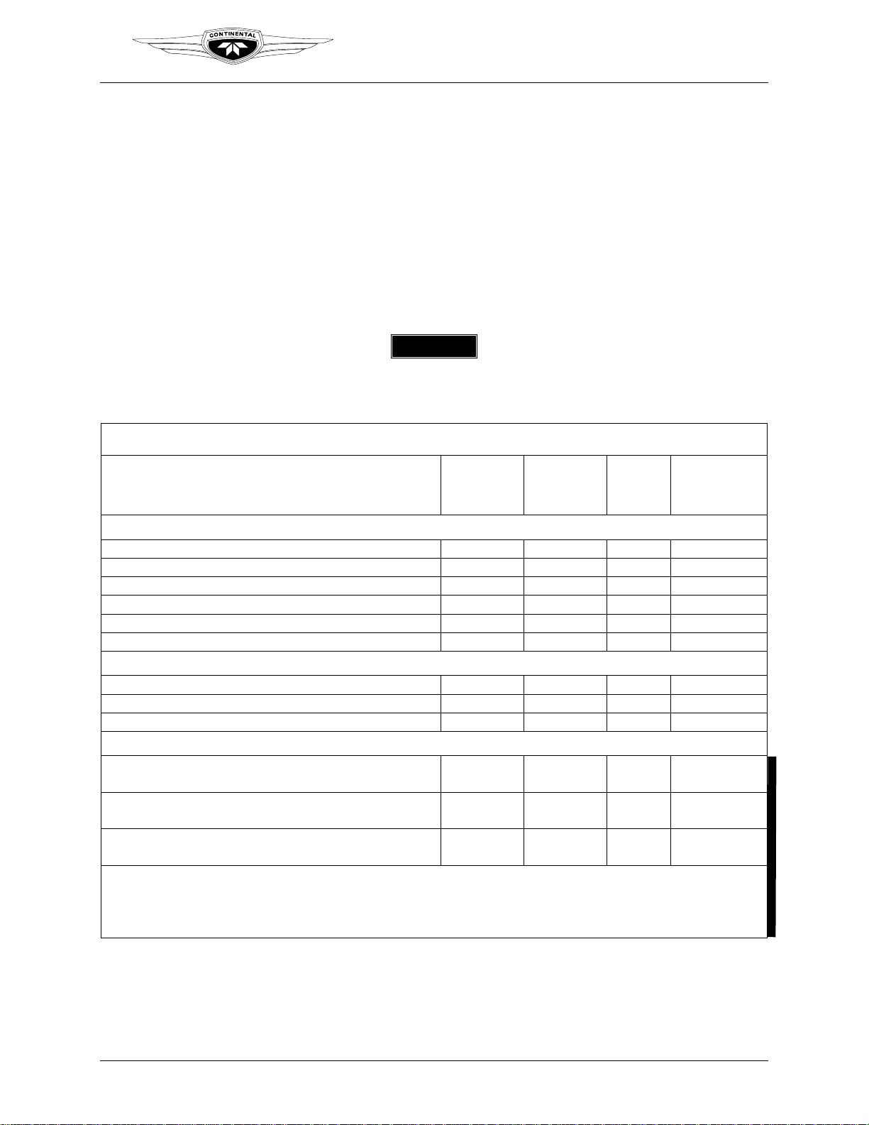
1-2.2. Related Publications
The chart below lists related publications, source, and accessibility relevant to installing,
maintaining, and overhauling the IOF-240 series engines.
Use only the latest revision of all publications. Using
superseded information jeopardize engine airworthiness.
Introduction
WARNING
Table 1-1. Related Publications
Supplied
With
Publication
TCM Publications
Installation and Operation Manual (OI-22) Yes Yes Yes N/A
Overhaul Manual (OH-22) No Yes Yes N/A
Parts Catalogues No Yes No N/A
Detailed Model Specifications No No Yes N/A
Service Documents No Yes Yes N/A
Material Handling Specifications (MHS) No No Yes N/A
Supplier Bulletins
FAA Airworthiness Directives No Yes No N/A
Accelagold No Reference No Yes
Emhart Fastening Teknologies No Reference No Yes
Accessory Documents
Aerosance Engine Data Interface, EDI-100/200 Manual
(AM14164)
Kelly Aerospace Power Systems Alternator Overhaul
Manual (OE-A2)
Kelly Aerospace Power Systems Lightweig ht Series
Alternator Overhaul Manual (ES1010-1/2)
*TCMLINK Information Services® provides 24-hour-a-day access via the Internet. If you are a TCMLINK
subscriber, you can access TCMLINK to confirm and review the latest revision of this manual. If you have not
subscribed to TCMLINK through TCM and are using hardcopies, contact TCM (see Section
Information
”) to confirm that you have the latest revision of the manual.
Engine
No Reference No Yes
No Reference No Yes
No Reference No Yes
Internet
via
TCMLINK*
Order
From
TCM
1-3, “TCM Contact
Available
From
Manufacturer
IOF-240 Series Engine Maintenance Manual 1-7
31 August 2007 Change 1

Introduction
Teledyne Continental Motors, Inc.
1-2.3. Publication Access
TCMLINK Alpha Services, Information Services, Aviator Services, and FBO Services
programs provide an array of benefits including access to electronic versions of TCM
technical publications (manuals, service documents, and parts catalogs) via the Internet.
Aviator Services and Alpha Services memberships are free to TCM engine owners. FBO
and Information Services are available with a paid subscription fee. Contact a TCM
distributor to discuss service subscription options and pricing or visit our website
(Section
1-3, “TCM Contact Information”).
Printed TCM publications may be ordered through Teledyne Continental Motors
authorized distributors or via the Internet at TCMLINK. Your TCM printed document
purchase includes three years of updates at no extra charge. Use ““
Information
” in Section 1-3, or our Internet website.
1-2.4. Publication Changes
The instructions in this manual represent the best and most complete information
available at the time of publication. Product or process improvements may trigger
changes to existing product design specifications or procedures contained in publications.
As new technical information becomes available, TCM will deliver the updated
information to the customer in the most expedient manner.
TM
TCM Contact
New information may be contained in Teledyne Continental
Motors service documents. Service documents applicable to
engines and accessories within the scope of this manual must
be complied with as defined in these documents. This manual,
together with TCM’s Installation and Operation Manual (OI-
22), Service Documents, and other related publications noted
constitute the Instructions for Continued Airworthiness (ICAs)
prepared by Teledyne Continental Motors and approved by
the Federal Aviation Administration (FAA).
Teledyne Continental Motors releases publication changes in the form of either change
pages or complete publication revisions, depending upon the extent of change. Service
Documents may supplement or replace technical information contained in one
publication or an entire series of publications. Such Service Documents represent a
change to the published ICA until the individual publications incorporate the latest
technical information.
1-2.4.1. Update/Change Distribution
Updates are available via TCMLINK upon notification of FAA document approval. TCM
notifies engine owners of technical publication changes free of charge. TCM notifies
current TCMLINK service subscribers by mail as publications are updated. Current
subscribers receive a complete publication library on CD delivered quarterly. Printed
publication subscribers receive printed changes and revisions as they are released.
WARNING
1-8 IOF-240 Series Engine Maintenance Manual
Change 1 31 August 2007

Teledyne Continental Motors, Inc.
TM
Introduction
1-2.4.2. Suggestions and Corrections
Teledyne Continental Motors solicits and encourages user comments regarding suggested
changes to this manual. Direct recommended changes or questions to the attention of
“Publications” at the TCM address listed in Section 1-3, “TCM Contact Information.”
Notify TCM Customer Service immediately, using our toll-free number, if you discover
incorrect information which adversely affects safety.
1-3. TCM Contact Information
Teledyne Continental Motors is available to answer technical questions and encourages
suggestions regarding products, parts, or service. If customers have an inquiry or require
technical assistance, they should contact their local TCM distributor or TCM field
representative. To contact TCM, refer to the contact information below:
Teledyne Continental Motors, Inc.
P. O. Box 90
Mobile, AL 36601
Toll Free Customer Service Phone Numbers: 888-826-5465
Internet Address: http://www.tcmlink.com
IOF-240 Series Engine Maintenance Manual 1-9
31 August 2007 Change 1

Introduction
TM
Teledyne Continental Motors, Inc.
This Page Intentionally Left Blank
1-10 IOF-240 Series Engine Maintenance Manual
29 November 2006

Teledyne Continental Motors, Inc.
TM
Engine Description
Chapter 2. ENGINE DESCRIPTION
CONTENTS
Chapter 2. Engine Description..................................................................................................2-1
2-1. General Engine Description..................................................................................................2-3
2-1.1. Engine Model Number Definition............................................................................................................. 2-4
2-1.2. Cylinder Number Designations ................................................................................................................. 2-4
2-2. Detailed Engine Description.................................................................................................2-5
2-2.1. Crankcase .................................................................................................................................................. 2-5
2-2.2. Engine Drive Train.................................................................................................................................... 2-6
2-2.3. Accessory Case.......................................................................................................................................... 2-8
2-2.4. Cylinders..................................................................................................................................................2-10
2-2.5. Lubrication System.................................................................................................................................. 2-12
2-2.6. Ignition System ........................................................................................................................................ 2-14
2-2.7. Fuel System............................................................................................................................................. 2-15
2-2.8. Starter Assembly......................................................................................................................................2-18
2-2.9. Alternator................................................................................................................................................. 2-19
2-2.10. Engine Cooling...................................................................................................................................... 2-19
2-2.11. Induction System................................................................................................................................... 2-20
2-3. Engine Specifications and Operating Limits......................................................................2-21
2-3.1. Accessory Drive Ratios........................................................................................................................... 2-23
2-3.2. Oil Specifications.................................................................................................................................... 2-23
2-3.3. Performance Data.................................................................................................................................... 2-24
LIST OF TABLES
Table 2-1. IOF-240-B Specifications and Operating Limits .....................................................2-21
Table 2-2. Accessory Drive Ratios, Rotation, Speed, Torque & Moments...............................2-23
Table 2-3. Engine Oil Type Requirements................................................................................2-23
IOF-240 Series Engine Maintenance Manual 2-1
31 August 2007 Change 1

Teledyne Continental Motors, Inc.
TM
Engine Description
LIST OF FIGURES
Figure 2-1. Engine Model Identifier............................................................................................2-4
Figure 2-2. Cylinder Number Designation ..................................................................................2-4
Figure 2-3. IOF-240 Crankcase ...................................................................................................2-5
Figure 2-4. Engine Drive Train....................................................................................................2-6
Figure 2-5. Crankshaft.................................................................................................................2-6
Figure 2-6. Camshaft ...................................................................................................................2-7
Figure 2-7. Camshaft Gear...........................................................................................................2-8
Figure 2-8. Accessory Case .........................................................................................................2-9
Figure 2-9. Cylinder Assembly..................................................................................................2-10
Figure 2-10. Lubrication Schematic ..........................................................................................2-12
Figure 2-11. Oil Pump ...............................................................................................................2-13
Figure 2-12. Oil Cooler Adapter................................................................................................2-14
Figure 2-13. Fuel Injection System............................................................................................2-15
Figure 2-14. Fuel Pump .............................................................................................................2-16
Figure 2-15. Fuel Injector Nozzle..............................................................................................2-17
Figure 2-16. Starting System .....................................................................................................2-18
Figure 2-17. Engine Cooling Airflow........................................................................................2-19
Figure 2-18. Typical Crossflow Induction Airflow...................................................................2-20
Figure 2-19. IOF-240-B Fuel Flow vs. Brake Horsepower.......................................................2-25
Figure 2-20. IOF-240-B Sea Level Performance.......................................................................2-26
2-2 IOF-240 Series Engine Maintenance Manual
Change 1 31 August 2007

Teledyne Continental Motors, Inc.
TM
Engine Description
2-1. General Engine Description
The IOF-240 engines are four-cylinder, four-stroke reciprocating aircraft engines
designed for fixed pitch, ground adjustable, or electric constant speed propellers. There is
no provision for a hydraulic propeller governor.
These horizontally-opposed, air-cooled, naturally-aspirated engines have a wet oil sump,
high pressure Lubrication System, an overhead plenum intake manifold, a side-mounted
accessory drive pad and provisions for a downdraft exhaust system.
The engines are equipped with a Full Authority Digital Engine Control (FADEC) System
for continuously monitoring and controlling ignition timing, fuel injection timing, and
fuel mixture. The microprocessor-based FADEC System monitors engine operating
conditions and then automatically sets the fuel mixture and ignition timing accordingly
for any given power setting. Consequently, FADEC engines do not require magnetos and
eliminate the need for manual fuel/air mixture control. There is no fuel mixture control
lever in a FADEC engine.
A FADEC-controlled engine differs from a non-FADEC engine in that a cylinder can be
leaned or enriched individually without affecting the other cylinders. The FADEC
System controls the fuel supplied to each cylinder using solenoid-actuated sequential port
fuel injectors. An engine-driven, positive displacement vane fuel pump supplies fuel as
required to the injectors. The fuel pump is directly driven at the same speed as the
crankshaft. Therefore, fuel flow and fuel pressure vary directly with engine speed. Fuel
exits the pump, passes through a 32-micron fuel filter situated between the engine-driven
fuel pump and the fuel distribution block, where it filters particulates larger than 10microns. From this point, fuel travels to each fuel injector.
Since the fuel system requires fuel with minimum vapor to operate normally, an electric
boost pump is required for starting the engine and during low RPM operation. Ignition
spark is timed to the engine’s crank position. The timing is variable from cranking speed
up to 2,000 RPM depending on engine load conditions. The spark energy varies with
respect to engine load.
The FADEC System is electrically powered by the aircraft’s primary electrical bus and a
secondary power source (SPS); it is not self-excited. The SPS may be an alternator or
battery. It is used to supply power to the FADEC System independently from the
aircraft’s primary bus. If the SPS is a battery, it will be constantly charged by the
aircraft’s primary power bus. The charging current supplied to the SPS battery is
monitored by the Health Status Annunciator (HSA) and the charging circuit is protected
by a circuit breaker.
Electrical power to the FADEC System is controlled from the cockpit by two switches
used to interrupt the primary power and secondary power. The pilot starts, enables, and
stops the FADEC System using a conventional aircraft-style Ignition Switch.
IOF-240 Series Engine Maintenance Manual 2-3
31 August 2007 Change 1
Engine Description
Teledyne Continental Motors, Inc.
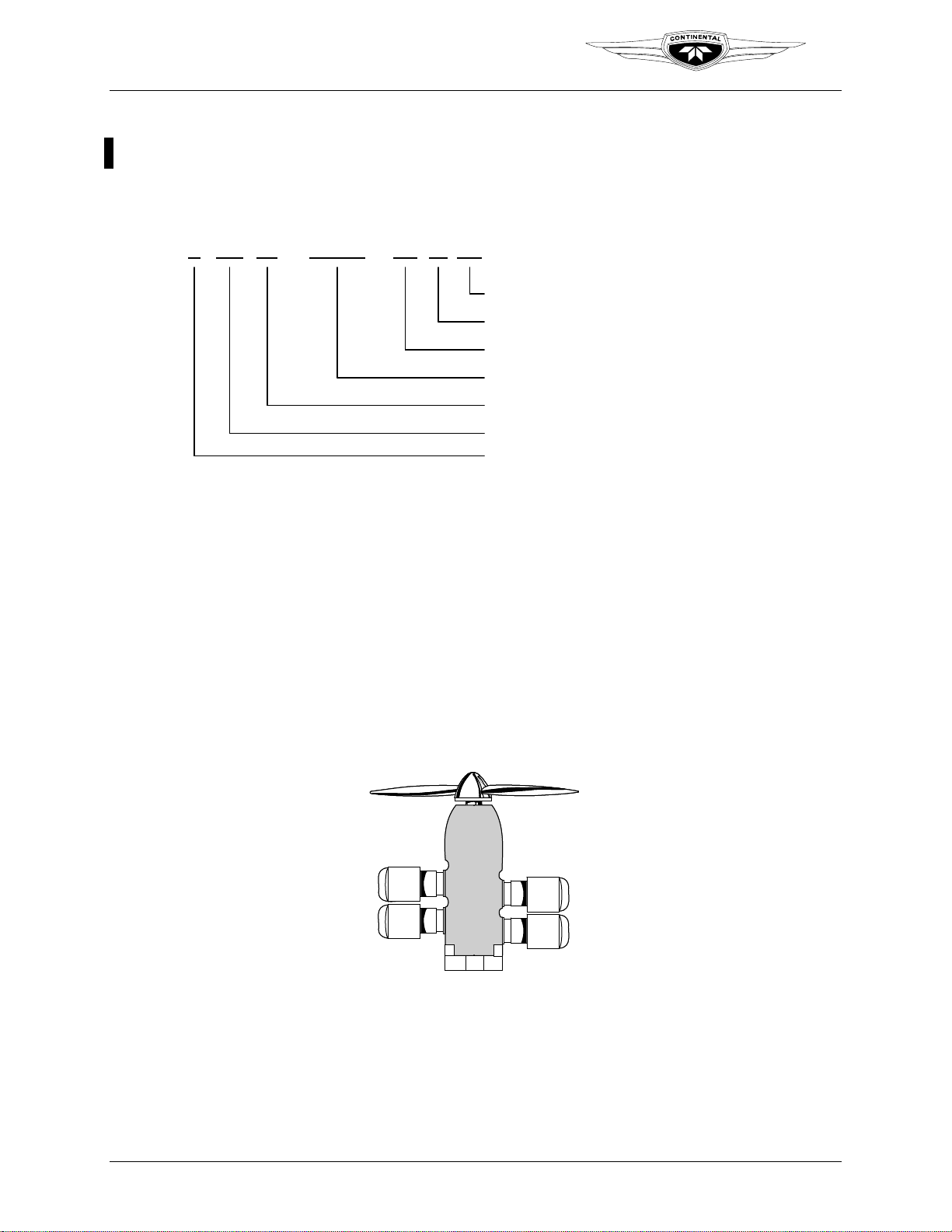
2-1.1. Engine Model Number Definition
The description of each alphanumeric character in the engine model number is given
below for the example engine model number IOF-240-B1B (Figure 2-1).
TM
I O F-240-B 1
I O F-240-B 1
Figure 2-1. Engine Model Identifier
2-1.2. Cylinder Number Designations
Refer to Figure 2-2:
• The front of the engine is the end closest to the propeller and the rear of the engine
is the accessory end
• Viewed from the rear of the engine, the left-side cylinders are designated by even
numbers 2-4, with Cylinder 2 being closest to the rear.
• The right side cylinders have odd number sequential designation 1-3, with Cylinder
1 being closest to the rear.
• Firing order of the engine is 1-3-2-4.
B
B
Shipping Designation
Shipping Designation
Specification Number
Specification Number
Model Identifier
Model Identifier
Cubic Inch Displacement
Cubic Inch Displacement
FADEC-equipped
FADEC-equipped
Horizontally Opposed Cylinders
Horizontally Opposed Cylinders
Fuel Injected
Fuel Injected
2-4 IOF-240 Series Engine Maintenance Manual
Change 1 31 August 2007
4
4
2
2
Figure 2-2. Cylinder Number Designation
3
3
1
1
Teledyne Continental Motors, Inc.
TM
Engine Description
2-2. Detailed Engine Description
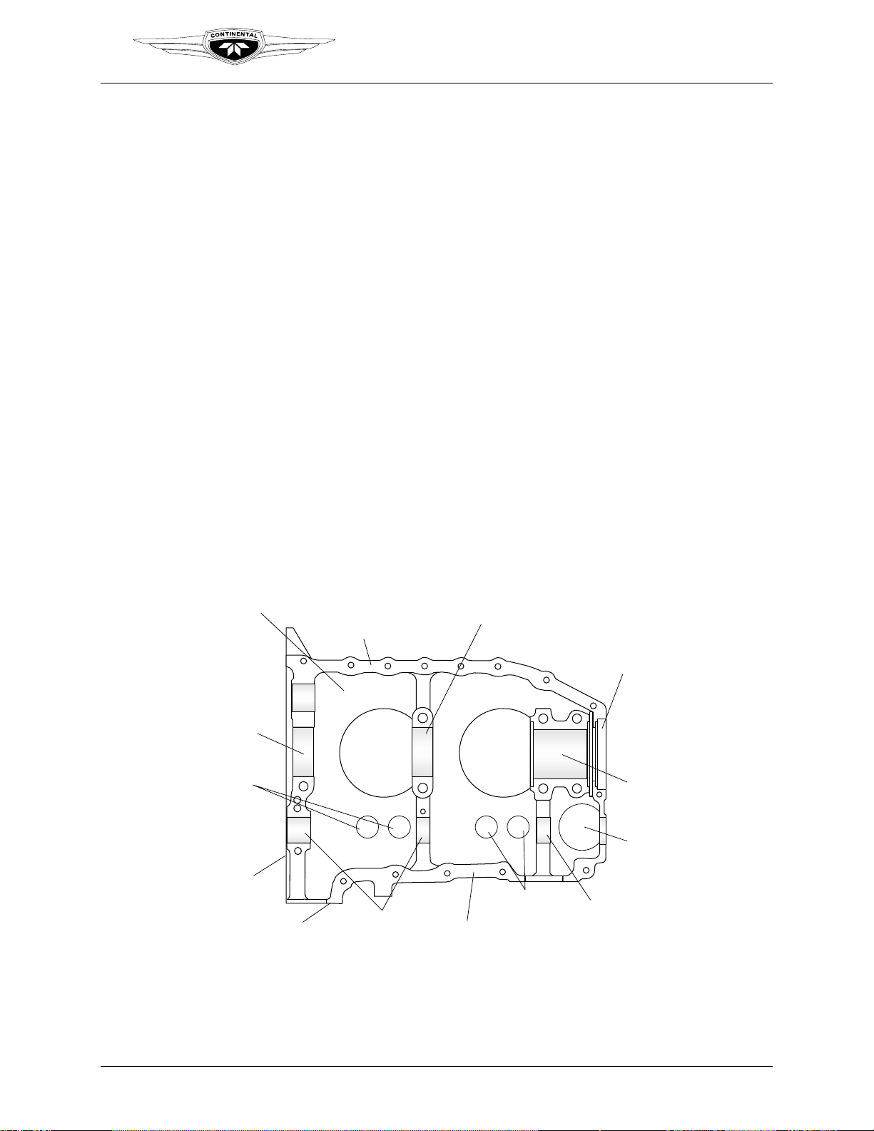
2-2.1. Crankcase
Two aluminum alloy castings are joined along the vertical center plane to form the
crankcase. The individual castings (with studs and inserts) are referred to as the "left
crankcase" and "right crankcase."
The crankcase provides:
• A tight enclosure, sufficiently rigid to provide support for the crankshaft, camshaft
and bearings.
• Oil galleries for lubrication.
Bosses molded in the crankcase castings are line bored in the assembled crankcase halves
to form bearings for the camshaft and saddles for precision crankshaft main bearing
inserts. Guides are bored through lateral bosses for hydraulic tappets. There are six studs
and two through-bolts for attaching cylinder base flanges. The fuel pump mounting pad is
located on the left crankcase half, forward of Cylinder 4.
Cylinder mounting pads on the left crankcase, beyond the corresponding pads on the right
crankcase, permit each connecting rod to work on a separate crankpin. The crankcase
interior is vented by a breather assembly comprised of a tube and baffle assembly with a
side extension for a hose attachment. The breather assembly is pressed into a boss on the
top side of the right crankcase half, forward of Cylinder 3.
2-4 OR L/H
CRANKCASE HALF
REAR CRANKSHFT
BEARING BORE
TAPPET
GUIDES
ACCESSORY CASE
MOUNT FLANGE
CRANKSHAFT BEARING BORE
BACKBONE
Cyl #2 Cyl #4
OIL SUMP
MOUNT FLANGE
CAMSHAFT
BEARING BORE
SPINE BELOW
CAMSHAFT
Figure 2-3. IOF-240 Crankcase
INTERMEDIATE
TAPPET
GUIDES
CRANKSHAFT NOSE
SEAL LAND
CRANKSHAFT
BEARING BORE
FUEL PUMP
CAMSHAFT
BEARING BORE
FRONT
ACCESS
IOF-240 Series Engine Maintenance Manual 2-5
31 August 2007 Change 1
Engine Description
Teledyne Continental Motors, Inc.
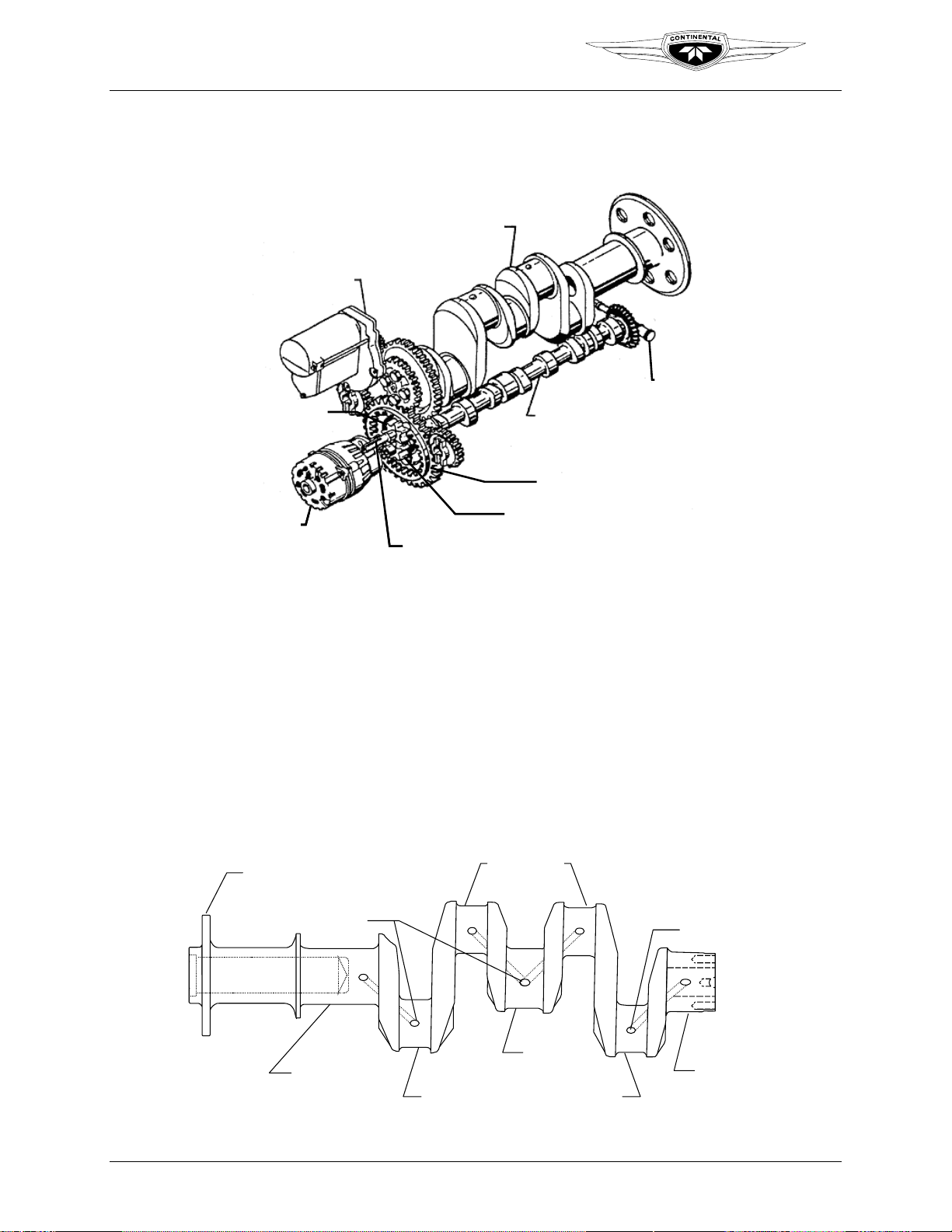
2-2.2. Engine Drive Train
The engine drive train consists of the crankshaft and camshaft.
Starter
Starter
Oil Pump
Oil Pump
Driven Gear
Driven Gear
Crankshaft
Crankshaft
Camshaft
Camshaft
Camshaft Gear
Camshaft Gear
Fuel pump and
Fuel pump and
vacuum pump
vacuum pump
drive shaft
drive shaft
TM
Alternator
Alternator
2-2.2.1. Crankshaft
The crankshaft (Figure 2-5) is made of aircraft quality steel and has three machined, main
journals which are supported by precision-bearing inserts in each of the three bearing
saddles machined in the crankcase. Four machined rod journals provide attachment of the
connecting rod assemblies. The crankshaft gear is indexed on the crankshaft by a dowel
and secured by machined bolts. A neoprene oil seal over the crankshaft flange is seated
between the crankcase castings in the front shaft exit area, and is sealed to the crankshaft
by a helical spring inside the seal's cavity.
CRANKSHAFT
FLANGE
Oil Pump Drive Gear
Oil Pump Drive Gear
Tachometer
Tachometer
Drive Shaft
Drive Shaft
Figure 2-4. Engine Drive Train
ROD JOURNAL
OIL
PASSAGE
#3
#2
OIL
PASSAGE
2-6 IOF-240 Series Engine Maintenance Manual
Change 1 31 August 2007
FRONT MAIN
JOURNAL
#4
ROD JOURNAL ROD JOURNAL
MIDDLE MAIN
JOURNAL
Figure 2-5. Crankshaft
#1
REAR MAIN
JOURNAL
Teledyne Continental Motors, Inc.
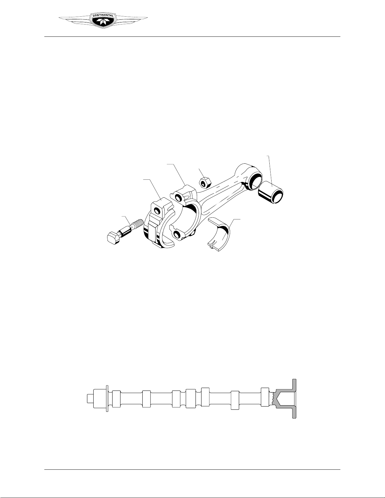
2-2.2.2. Connecting Rods
The connecting rods halves are machined from a single forging of aircraft quality steel
and cut into two pieces, splitting the center of the larger opening of the connecting rod
assembly. The resulting pieces, called the rod and cap are fitted with a two piece bearing
and attach to the crankpin or rod journal with special bolts and nuts.
The portion of the rod between the rod and the crankpin and piston pin ends is called the
“I” beam. A split steel-backed bronze bushing is pressed into the piston pin end and
machined for a precision pin-to-bushing fit. Weight variations between opposing
crankshaft positions is limited to ½ ounce (14.175 grams).
NOTE: Some older models use castellated nut with cotter pin
CONNECTING ROD
CAP
TM
CONNECTING ROD
Engine Description
BRONZE BUSHING
SPIRAL LOCK NUT
ROD BOLT
2-2.2.3. Camshaft
The camshaft forging is machined on three main journals, six cam lobes and the gear
mount flange at the rear of the camshaft. The lobes and journals are ground and hardened.
The main journals of the camshaft are supported in the crankcase by machined bearing
saddles. Hydraulic tappets move inward and outward in their bores, following the
eccentric shape of the cam lobes. Four unequally spaced bolts secure the gear to the
camshaft and ensure proper positioning, locating the gears’ timing mark in relation to the
cam lobes. The camshaft gear has internal teeth for driving the alternator. A frontmounted, keyed bevel gear drives the accessory drive bevel gear which drives the fuel
pump through a common shaft.
FRONT REAR
SHELL
BEARING
#4 EXH #3 EXH #2 EXH #1 EXH
#3 & 4
INTAKE
#1 & 2
INTAKE
M/J
IOF-240 Series Engine Maintenance Manual 2-7
31 August 2007 Change 1
C/L C/L C/L C/L C/L C/L
M/J M/J
M/J - MAIN JOURNAL
C/L - CAM LOBE
Figure 2-6. Camshaft
Teledyne Continental Motors, Inc.
TM
Engine Description
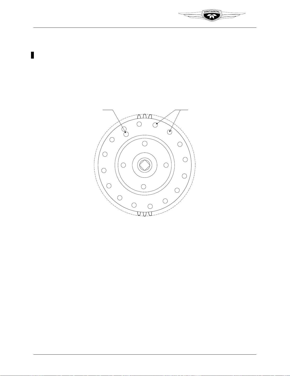
The camshaft gear (Figure 2-7) has 16 holes drilled in the outer track and one hole drilled in the
inner track. The speed pulse generated by the 16 hole-outer track is the Ne Pulse and the Nc
pulse is generated by the lone hole in top dead center inner track for Cylinder 1. As the camshaft
gear rotates, the holes in the gear are detected by the Speed Sensor Assembly (SSA).
The SSA consists of two pairs of sensors which detect steel density changes that occur when the
drilled holes in the camshaft gear pass by the sensor array. Detection of the open holes is sent as
a cam pulse signal to the FADEC Electronic Control Units (ECUs). The ECUs determine the
engine speed based on input from the SSA sensors signals which detect the speed pulses from the
camshaft gear outer track (Ne pulse) and the inner track (Nc pulse).
1 Nc Pulse
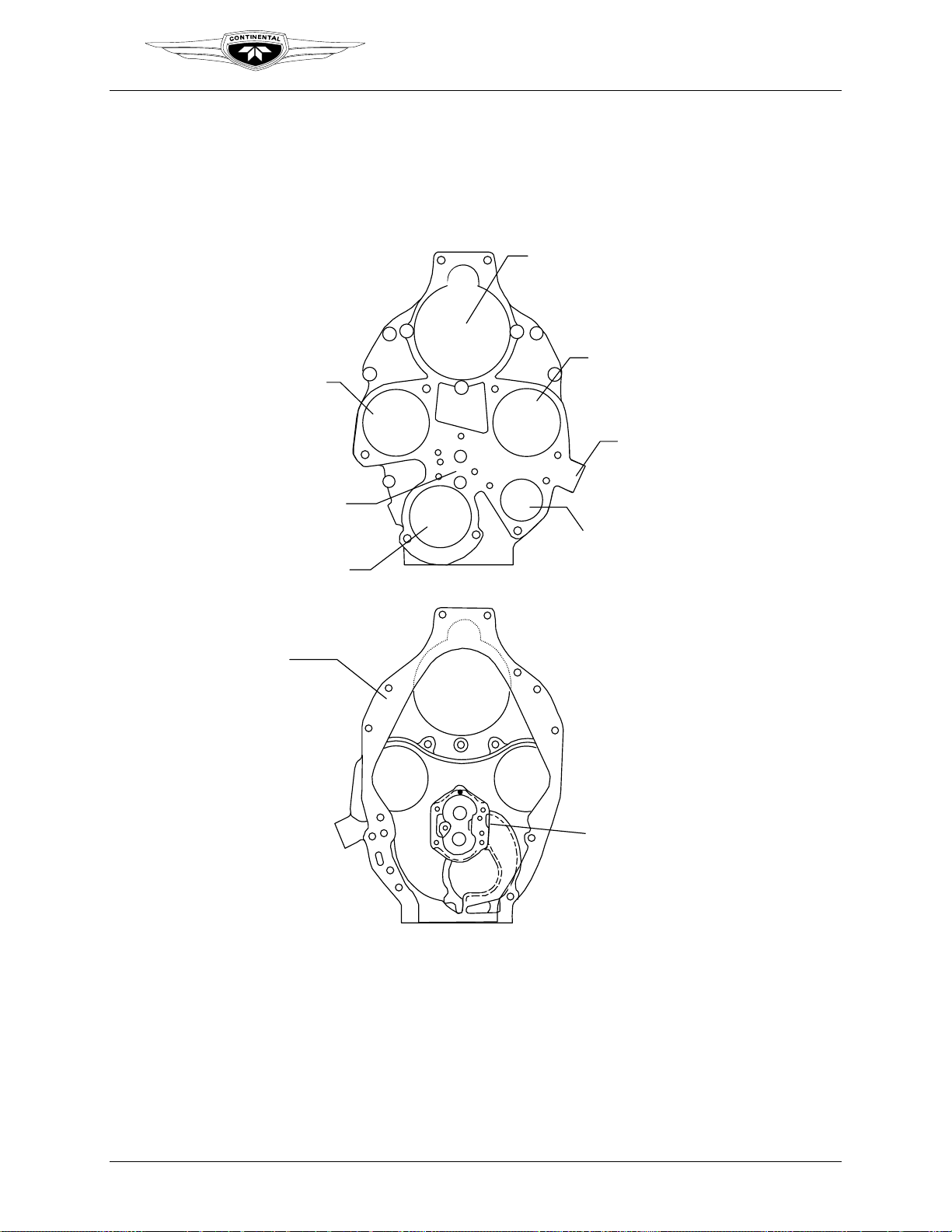
2-2.3. Accessory Case
The aluminum alloy casting of the accessory case is attached to the rear of the engine
crankcase, aligned with crankcase dowels; the accessory case is secured to the crankcase
by crankcase studs and various attaching hardware. Accessory mount pads on the rear
surface are machined in one plane parallel to the machined parting flange which
surrounds the front side of the casting. Mounting pads for the magnetos, alternator cover,
starter, tachometer drive, oil filter adapter, oil pressure relief valve and an oil suction
screen boss are provided. The accessory case casting has two holes above and three studs
to attach the starter and starter adapter. A mounting pad is provided for an oil screen
housing in lieu of the screw-on type oil filter.
The oil pump housing is machined into the internal portion of the accessory case. A
machined, threaded boss is located on the lower right side of the accessory case for
installation of a non-adjustable oil pressure relief valve. Oil pump gear chambers are
machined in the interior of the accessory case. The oil pump drive gear shaft hole is
machined in-line with the camshaft and the driven gear shaft hole is directly above it.
16 Ne Pulses
Figure 2-7. Camshaft Gear
2-8 IOF-240 Series Engine Maintenance Manual
Change 1 31 August 2007
Teledyne Continental Motors, Inc.
TM
Engine Description
A semicircular opening at the accessory case bottom is a machined threaded hole to
accommodate installation of the oil suction tube. Passages cast into the accessory case
allow oil to flow from the oil suction tube to the oil pump gears, pressure relief valve, and
main oil gallery. The tachometer drive shaft is the slotted end of the oil pump driven gear
shaft.
STARTER MOUNTING
STARTER MOUNTING
PAD
PAD
MAGNETO MOUNTING
MAGNETO MOUNTING
PAD COVERED
PAD COVERED
SPEED
SPEED
SENSOR
SENSOR
PAD
PAD
OIL PRESSURE
OIL PRESSURE
RELIEF VALVE
RELIEF VALVE
HOUSING
HOUSING
TACH DRIVE
TACH DRIVE
MOUNTING
MOUNTING
PAD
PAD
OIL SCREEN
ALTERNATOR
ALTERNATOR
MOUNTING
MOUNTING
PAD
PAD
OIL SCREEN
HOUSING
HOUSING
MOUNTING
MOUNTING
PAD
PAD
INSIDE VIEW
INSIDE VIEW
ACCESSORY
ACCESSORY
OF
OF
CASE
CASE
Figure 2-8. Accessory Case
OIL PUMP
OIL PUMP
IOF-240 Series Engine Maintenance Manual 2-9
31 August 2007 Change 1
Engine Description
Teledyne Continental Motors, Inc.
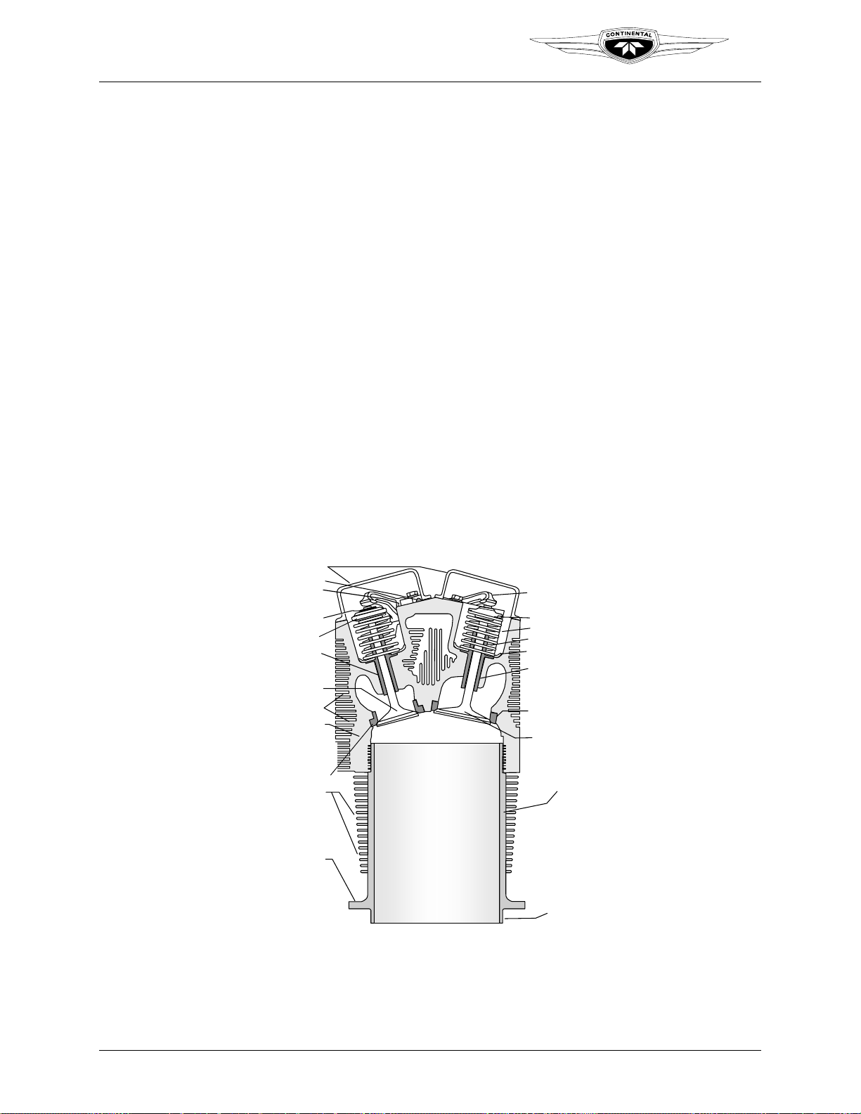
2-2.4. Cylinders
The IOF-240 engine has four, horizontally-opposed, air cooled cylinders, two on the left
side and two on the right side of the engine. The cylinders, pistons and valve drive train
provide the momentum to sustain crankshaft movement. Aviation fuel and air are drawn
into a cylinder during the intake stroke, compressed by the piston during the compression
stroke and then ignited by a high intensity spark from each spark plug (two per cylinder).
As the mixture is ignited, the expanding gases force the piston to move inward toward the
crankshaft during the power stroke.
The head and barrel assembly consists of externally finned aluminum alloy head casting
and a steel, nitrided cylinder barrel for wear resistance. Helical coil thread inserts are
installed in upper and lower spark plugs holes. A rotocoil assembly retains two concentric
springs surrounding the exhaust valve and is locked to the stem by tapered, semi-circular
keys which engage grooves around the valve stems. An outer retainer holds two
concentric springs which surround the intake valve and is locked to the stem by tapered,
semi-circular keys which engage grooves on the stem.
IOF-240 engines use a cross flow cylinder head design. The intake ports are located on
top of the cylinder head while the exhaust ports are located below. There are separate
intake and exhaust valve rocker covers made from zinc-plated stamped sheet steel. This
cylinder design is used in conjunction with a Balanced Induction System mounted above
the engine.
TM
ROCKER COVER
ROCKER SHAFT
THRUST WASHER
(ONE ON EACH SIDE
OF EACH ROCKER ARM)
VALVE RETAINER
KEYS
ROTOCOIL
EXHAUST
VALVE GUIDE
EXHAUST
VALVE
COOLING FINS
CYLINDER HEAD
EXHAUST
VALVE
SEAT
INSERT
CYLINDER BARREL
COOLING FINS
CYLINDER BASE
FLANGE
Figure 2-9. Cylinder Assembly
ROCKER ARM
RETAINER
OUTER SPRING
INNER SPRING
SPRING SEAT
INTAKE VALVE GUIDE
INTAKE VALVE
SEAT INSERT
INTAKE VALVE
CYLINDER BARREL
CYLINDER SKIRT
2-10 IOF-240 Series Engine Maintenance Manual
Change 1 31 August 2007
Teledyne Continental Motors, Inc.
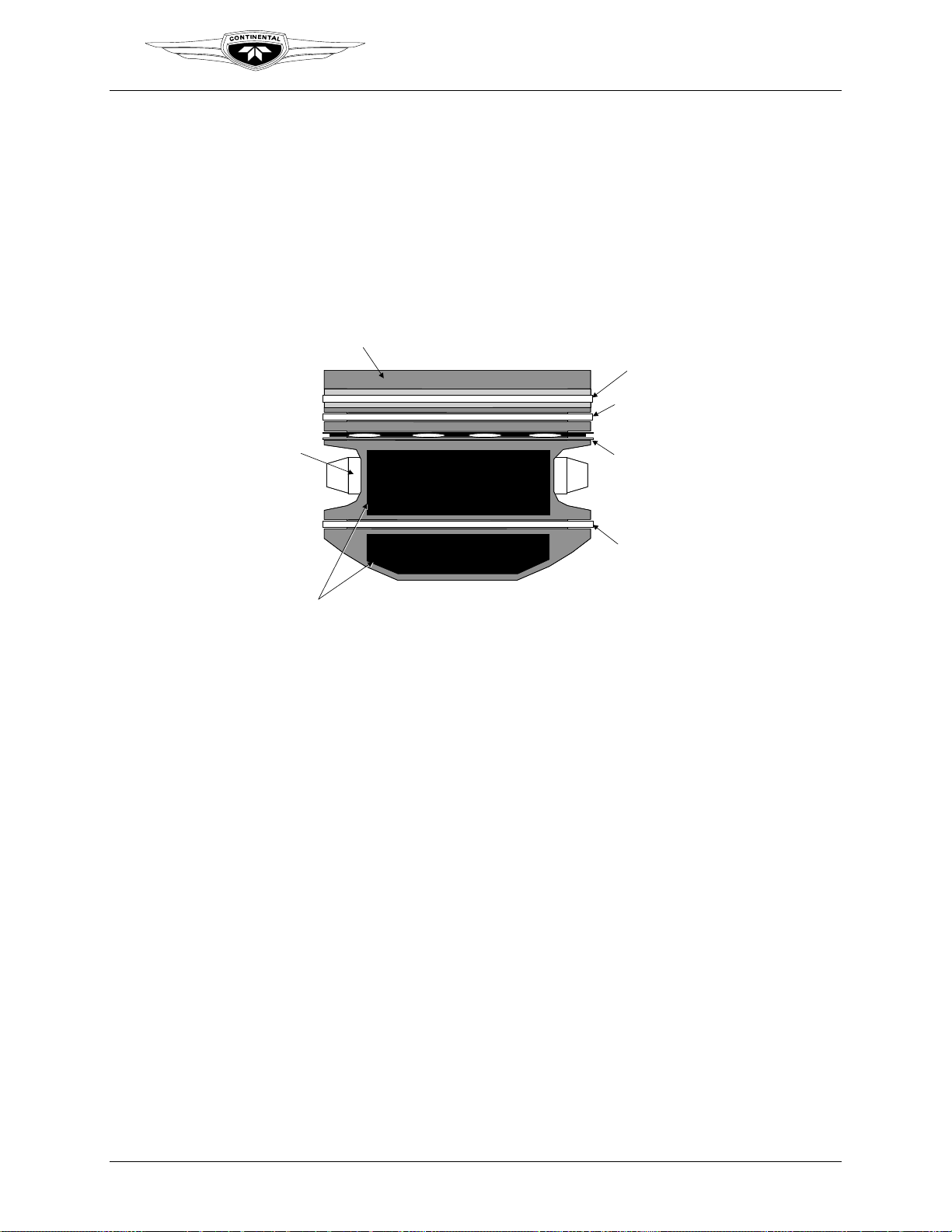
2-2.4.1. Pistons
Pistons are aluminum alloy castings with a steel insert cast into the top ring groove. The
skirts are solid and have cylindrical relief cuts at the bottom. Pistons have three ring
grooves above the piston pin hole and one ring groove below. Compression rings are
installed in the top and second grooves. The groove below the pin hole contains an oil
scraper. A center grooved and slotted oil control ring is installed in the third groove
which has six oil drain holes to the interior. Weight differences are limited to ½ ounce
between opposing cylinders bays. Piston pins are full floating with permanently pressedin aluminum end plugs.
TM
Engine Description
MANGANESE PHOSPHATE COATING
PISTON PIN
GRAPHITE COATED SKIRT
2-2.4.2. Hydraulic Valve Tappets
The hydraulic lifter performs two functions. First, it provides an interface between the
camshaft lobe and the remaining valve train. Hydraulic valve lifters ride on the eccentric
cam lobes opening and closing the intake and exhaust valves mechanically via push rod
tubes and rocker arms. This allows conversion of the cam lobe profile into a linear
movement for actuation of the intake and exhaust valves. Secondly, the hydraulic
mechanism inside the lifter maintains zero clearance between the valve and its actuating
components.
The interface between a cam lobe and lifter is intended to wear to some degree as the
engine operates. This is similar to the piston ring / cylinder wall interface that must seat
together for proper operation and wear over time.
ST
COMPRESSION
1
RING
ND
2
COMPRESSION
RING
OIL CONTROL
RING
OIL SCRAPER
RING
IOF-240 Series Engine Maintenance Manual 2-11
31 August 2007 Change 1
Engine Description
Teledyne Continental Motors, Inc.
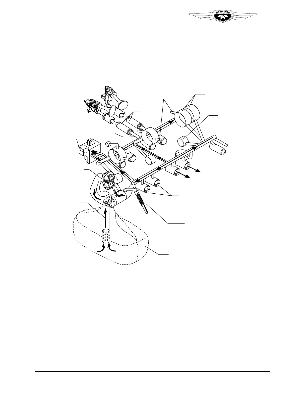
2-2.5. Lubrication System
The engine lubrication system delivers lubricating oil throughout the engine to various
bearings, bushings, and engine components. The wet sump, high pressure lubrication
system consists of an internal engine-driven oil pump, a non-adjustable pressure relief
valve, an oil sump, oil sensing ports. The oil cooler adapter is provided to connect an
optional remote mounted oil cooler.
TM
OIL COOLER
ADAPTER
OIL PUMP
GEARS
OIL
SUCTION
TUBE
INTAKE
PUSHROD
EXHAUST
OIL SQUIRT
NOZZLE
PUSHROD
HOUSING
CRANKSHAFT
BEARINGS
CAMSHAFT
BOSS
VACUUM
PUMP
BUSHING
HYDRAULIC
LIFTERS
OIL PRESSURE
RELIEF VALVE
2-2.5.1. Oil Pump
The engine-driven, gear type oil pump (
consists of two meshed steel gears that revolve inside the oil pump cavity machined in
the accessory case. The camshaft drives the oil pump drive gear, which drives the oil
pump driven gear. The oil pump driven gear is supported by a shaft pressed into the
accessory case and supported by the oil pump cover plate. The oil pump drive gear shaft
is supported by bushings pressed into the accessory case. The oil pump gear shaft
incorporates provisions to drive a mechanical tachometer.
The oil pump housing and oil pump gear chambers are machined in the interior of the
accessory case. The oil pump drive gear shaft hole is machined in-line with the camshaft
and the driven gear shaft hole is directly above it.
2-12 IOF-240 Series Engine Maintenance Manual
Change 1 31 August 2007
OIL SUMP
Figure 2-10. Lubrication Schematic
Figure 2-11) is a positive displacement pump that
 Loading...