

Page 1

IO-240-A
CONTINENTAL® AIRCRAFT ENGINE
B
INSTALLATION
AND
OPERATION
MANUAL
FAA APPROVED
Publication OI-6
©
2011 CONTINENTAL MOTORS, INC. OCT 2011
Page 2

Supersedure Notice
This manual is a revision of the Continental Motors IO-240 Operation and Installation Manual, Part No. X30620,
released on January 1996. Upon FAA Approval, this manual supersedes X30620 in its entirety.
Effective Changes for this Manual
0..........31 October 2011
List of Effective Pages
Document Title: IO-240 Series Engine Installation & Operation Manual
Publication Number: OI-6 Initial Publication Date: 31 October 2011
Page Change Page Change Page Change Page Change
Cover............................0
A...................................0
i-xii................................0
1-1 thru 1-10.................0
2-1 thru 2-32.................0
3-1 thru 3-30.................0
4-1 thru 4-28.................0
A-1 thru A-4..................0
B-1 thru B-10................0
C-1 thru C-20 ...............0
Published and printed in the U.S.A. by Continental Motors, Inc.
Available exclusively from the publisher: P.O. Box 90, Mobile, AL 36601
Copyright © 2011 Continental Motors, Inc. All rights reserved. This material may not be reprinte d, republished, broadcast, or o therwise
altered without the publisher's written permission. This manual is provided without express, statutory, or implied warranties. The publisher will
not be held liable for any damages caused by or alleged to be caused by use, misuse, abuse, or misinterpretation of the contents. Content is
subject to change without notice. Other products and companies mentioned herein may be trademarks of the respective owners.
A IO-240 Series Engine Installation & Operation Manual
31 October 2011
Page 3

Service Document and Technical References
Technical information in the service documents listed below relevant to the engine models
covered by this engine manual have been incorporated in the manual. The full content of active
Continental Motors engine service documents is available http://continentalmotors.aero. Refer to
Section 1-3, “Contact Information” for Continental Motors web site details.
Service Document Subject Affected Chapter
M64-18, Turbocharger Field Conversion Engine Modification N/A
M72-17R1, Maximum Weight Difference Allowance Between
Connecting Rods and Pistons in the Same Engi ne
M73-13, Reaming and Bushing Rocker Shaft Bosses
M75-6R1, Conversion of Engines From One Model to Another Engine Configuration N/A
M76-4, Installation Of Propeller Shaft Or Nose Oil Seals Oil Seal Replacement N/A
M76-5R1, Remote Mounted Oil Coolers
M76-8, Intake Valve Change
M76-15, Fuel Pumps
M77-19, Intake and Exhaust Rocker Arm Identification and
Application
M81-8R1, Fuel Pump Screen Restriction
M81-25, Exhaust Flange to Cylinder Installation Procedures Engine Installation N/A
M86-9, Crankcase Modification Engine Overhaul N/A
M87-15, Alternator Ground Strap Alternator Replacement N/A
M88-9, Lightning Strikes Unscheduled Maintenance 4
M88-10, Contaminated Fuels Unscheduled Maintenance 3 & 4
M89-7R1, Engine Operation after Cylinder Replacement and/or
Major Overhaul
M89-9, Excessive Crankcase Pressure Unscheduled Maintenance 4
M89-18, EGT Recommendations EGT Leaning 4
M90-9, New TCM Magneto and Harness Applications
M90-13, Exhaust Valve Stem Corrosion/Erosion Inspection & Overhaul N/A
M90-17, Crankcase Inspection Criteria Inspection N/A
M91-4, Piston Identification and Piston Ring Application Bulletin Piston Replacement N/A
M91-9, Cam and Lifter Lubrication during Rebuild Overhaul N/A
M93-8, Rocker Arm to Rotocoil Clearance Rocker Arm Clearance N/A
M93-10, TCM Ignition Systems Service Bulletin 639 Inspection N/A
SIL93-11A, New Service Document Format Service Documents 1
MSB93-12, Valve Retainer Key Installation Inspection Inspection N/A
SIL93-14, CFC Compliance N/A N/A
Engine Assembly and
Overhaul
Cylinder Repair and
Overhaul
Engine Installation and Oil
Servicing
Engine Maintenance and
Overhaul
Fuel Pump and Camshaft
Replacement
Engine Assembly N/A
Fuel Pump Inspection and
Parts Replacement
Engine Operation-break-in 4
Magneto and Ignition
Harness Replacement
N/A
N/A
N/A
N/A
N/A
N/A
N/A
IO-240 Series Engine Installation & Operation Manual i
31 October 2011
Page 4

Service Document Subject Affected Chapter
SIL93-15, General Practices for Installation of Lock Wire, Tab
Washers, and Cotter Pins
CSB94-1, TCM Ignition CSB641 Magneto Coil N/A
SIL94-5, Mobil AV-1 Oil Authorized Lubricants N/A
MSB94-8D, Magneto to Engine Timing Service N/A
SB95-2, Inspection and Maintenance of Engine Control Cables
and Linkage
SB95-3B, Alternator/Generator Drive Couplings Inspection N/A
CSB95-4, Intake Valve Guide Seal Inspection N/A N/A
SIL95-5, Hose and Tubing Installation Hose and tubing installation Appendix C
CSB96-1, Starter Gear and Clutch Assembly, P/N 653575 Starter Replacement N/A
SID96-6, TCM Ignition SB653
SB96-7C, Torque Limits fastener torque Appendix B
MSB96-10, Requirements for Ultrasonic Inspection
SB96-11B, Propeller Strikes and Hydraulic Lock Scheduled Inspection 4
SB96-12, Continued Airworthiness for TCM Cylinders Scheduled Inspection N/A
SIL97-1, Airworthiness Limitations Airworthiness Limitations N/A
SID97-2B, TCM Cylinder Warranties N/A N/A
SID97-3E,Procedures and Specifications for Adjustment of TCM
Continuous Flow Fuel Injection Systems
SID97-4C, Cylinder Bore and Piston Fit Specifications Overhaul & Service Limits N/A
SB97-6B, Mandatory Replacement Parts
CSB97-10A, Piston Pin Plug Wear Service Limits N/A
SIL97-14, Replacement Cylinder Assembly Cylinder Replacement N/A
SB97-15, TCM Ignition Service Bulletin SB660 N/A N/A
CSB98-1B, Intake and Exhaust Valve Inspection Service Limits N/A
SIL98-9A, Time Between Overhaul Periods
SIL99-1, Engine Preservation for Active and Stored Aircraft
SIL99-2C, Current Listing of Sealants, Lubricants and Adhesives
Authorized by TCM
SB99-8, Engine Fuel Injection System Preservation
SB00-3A, Crankshaft, Counterweight and Connecting Rod
Repair Information
SB00-4A, Australian AVGAS Contamination Inspection and Operation N/A
SIL00-7A, Oil Gauge Rod Application Oil Servicing N/A
SIL00-9A, Engine Data Plates N/A N/A
SB00-10, Fuel Pump Seal Fuel Pump Installation N/A
Standard Practices Appendix C
Inspection N/A
Engine Operation-Hot
magneto Test
Crankshaft Removal &
Replacement
Engine Operational Check
and Engine Specifications
Engine Inspection &
Assembly
Engine Specifications,
Scheduled Maintenance
Engine preservation and
returning an engine to
service after storage
Materials Throughout
Fuel Injection system
storage
Repair Specifications N/A
4
N/A
3, 4
Appendix C
2
3
3
ii IO-240 Series Engine Installation & Operation Manual
31 October 2011
Page 5

Service Document Subject Affected Chapter
SIL00-11B, Release of new Cylinder Induction Port Drain
Connector
CSB02-8, TCM Ignition Systems CSB664 N/A N/A
SIL03-1, Cold Weather Operation – Engine Preheating Preheating procedures 4
SIL03-2B, Currently Active Approved Spark Plug Application Spark plugs 2 & 3
SIL03-3, Differential Pressure Test and Borescope Inspection Inspection Criteria N/A
SIL03-7, IO-240 Series Magneto Drive Gear Inspection Criteria N/A
SIL04-2, Cylinder Barrel Ultrasonic Inspection N/A N/A
SB04-4, Manifold Valve Spring Replacement Overhaul Repairs N/A
CSB04-5A, TCM Ignition Systems CSB665A Magneto Service N/A
SB04-10, Piston Pin Marking Overhaul Repairs N/A
SB04-11, Valve Guide Application, Installation and Reaming Valve Guide Repairs N/A
SIL04-1A, Installation of Optional Altitude Compensating Fuel
Pump on IO-240-B Series Engines
SIL04-8 Optional Replacement Starter fo IO-240 Series Engines
SIL04-9, IO240B13B Manifold Valve Replacement, Heat Isolation
Modifications, and Throttle Body Modifications
SIL04-12A, TCM Authorized Engine Adjustments, Component
Replacement and Repositioning
SID05-1, Design, Operation and Maintenance of TCM Camshafts
and Hydraulic Lifters
SB05-2, Overspeed Limitations Unscheduled Maintenance 4
SIL05-3, Engine Specification Numbers Engine Specification 2
SIL05-4A, IO-240 Series PN 656850 Inline Fuel Filter Installation
and Inspection Procedures
SIL05-5A, IO-240-B Series Manifold Valve Fuel Scavenge
System Installation
SIL05-6A, IO-240-B Series Product Upgrades
SB07-1, Connecting Rod Piston Pin Bushing Inspection Inspection N/A
SB07-3, Procedures and Specifications for adjustment of TCM
IO-240-B17B Fuel Injection System installed on Diamond DA20C1 Aircraft
SB07-8, Recommended Minimum RPM & Manifold Pressure
Cruise Operations Limits
SB08-3A, Throttle & Mixture Control Arms N/A 4
SB08-4, Fuel Injection System Contamination
SB08-8, Slick Service Bulletin SB2-08 Magneto Inspection N/A
SB08-9A, Slick Service Bulletin SB3-08A Magneto Inspection N/A
Cylinder Assembly N/A
Fuel System Specification
and Engine Operational
Check
Engine Specification and
Parts Replacement
Engine Specification 3, 4
Engine Specification N/A
Inspection Criteria N/A
Engine Specification,
Inspection, Component
Replacement
Engine Specification,
Inspection, Component
Replacement
Engine Specification,
Inspection, Component
Replacement
Engine Specification,
Inspection, Component
Replacement
Engine Operation 4
Engine Specification,
Inspection, Replacement
3, 4
3, 4
3
3
3
3 & 4
3
IO-240 Series Engine Installation & Operation Manual iii
31 October 2011
Page 6

Service Document Subject Affected Chapter
SB08-13, Induction System Hose and Clamp Installation
SB09-14, Camshaft Corrosion Treatmen Engine Inspection N/A
SIL640, Service Document Format Service Documents Preface & 1
SB643B, Maintenance Intervals for TCM Bendix Magnetos Inspection & Operation N/A
SB653, Hot Magneto Test Inspection & Operation 3 & 4
Induction System
Inspection & Assembly
Appendix C
Service Documents Released After Publication
Continental Motors strives to provide clear, concise, and accurate information and instructions
based on best known engineering data at the time of publication. Ongoing process improvements
may change a specification or procedure after a manual is released. Service documents, defined in
Chapter 1, expedite customer notification and serve as the prevailing instruction over conflicting
information until the new information is incorporated in the manual text. As service documents
are received, note the service document number , releas e date, title, a nd applicable sec tion af f ected
by the service document in the blank cells below and insert a copy of the service document behind
the last page of this section. Make pen & ink corrections, where appropriate, to the original text in
the manual with a citation to the service document; i.e. see SB9X-1. For paragraphs or entire
sections, draw an “X” through the affected information in the manual and reference the service
document containing the correction.
Service Bulletins Release After This Manual
Bulletin Number: Release Date:
Title:
Bulletin Number: Release Date:
Title:
Bulletin Number: Release Date:
Title:
Bulletin Number: Release Date:
Title:
Bulletin Number: Release Date:
Title:
Bulletin Number: Release Date:
Title:
Bulletin Number: Release Date:
Title:
Bulletin Number: Release Date:
/ /
/ /
/ /
/ /
/ /
/ /
/ /
/ /
Affected Sections:
Affected Sections:
Affected Sections:
Affected Sections:
Affected Sections:
Affected Sections:
Affected Sections:
Affected Sections:
Title:
iv IO-240 Series Engine Installation & Operation Manual
31 October 2011
Page 7

Service Bulletins Release After This Manual
Bulletin Number: Release Date:
Title:
Bulletin Number: Release Date:
Title:
Bulletin Number: Release Date:
Title:
Bulletin Number: Release Date:
Title:
Bulletin Number: Release Date:
Title:
Bulletin Number: Release Date:
Title:
Bulletin Number: Release Date:
Title:
Bulletin Number: Release Date:
/ /
/ /
/ /
/ /
/ /
/ /
/ /
/ /
Affected Sections:
Affected Sections:
Affected Sections:
Affected Sections:
Affected Sections:
Affected Sections:
Affected Sections:
Affected Sections:
Title:
Bulletin Number: Release Date:
Title:
Bulletin Number: Release Date:
Title:
Bulletin Number: Release Date:
Title:
Bulletin Number: Release Date:
Title:
Bulletin Number: Release Date:
Title:
Bulletin Number: Release Date:
Title:
Bulletin Number: Release Date:
Title:
/ /
/ /
/ /
/ /
/ /
/ /
/ /
Affected Sections:
Affected Sections:
Affected Sections:
Affected Sections:
Affected Sections:
Affected Sections:
Affected Sections:
Bulletin Number: Release Date:
IO-240 Series Engine Installation & Operation Manual v
31 October 2011
/ /
Affected Sections:
Page 8

PREFACE
Continental Motors provides Instructions for Continued Airworthiness based on the design,
testing, and certification of engines and parts for which Continental Motors is the holder of the
Type Certificate (TC) or Parts Manufacture Approval (PMA) issued by the Federal Aviation
Administration (FAA). Instructions in Continental Motors engine manuals, which include
maintenance, repair limits, overhaul, and installation, are applicable only to engines and parts
supplied by Continental Motors.
Except for F AR part 43.3 authorized owner preventive maintenance, Continental Motors ICAs are
written for exclusive use by FAA (or equivalent authority) licensed mechanics or FAA (or
equivalent authority) certified repair station employees working under the supervision of an FAA
licensed mechanic. Information and instructions contained in this manual anticipate the user
possesses and applies the knowledge, training, and experience commensurate with the
requirements to meet the prerequisite FAA license and certification requirements. No other use is
authorized.
Installation of aftermarket parts on a Continental Motors engine constitutes a deviation from FAA
approved type-design criteria. Continental Motors has not participated in design, test, or
certification of any aftermarket parts. Continental Motors does not provide product manufacturing
specifications to aftermarket parts manufacturers and accepts no liability for the suitability,
durability, longevity, or safety of such parts installed on Continental Motors engines. Installation
of aftermarket parts on a Continental Motors engine must be performed using Instructions for
Continued Airworthiness prepared by the manufacturer and accepted by the FAA for the subject
installation. Continental Motors ICAs must not be used for such parts.
Service documents may contain general information or information specific to a group of engines
or be in effect for a limited time frame. Service Documents may also contain advance changes to
the ICAs. It is the responsibility of the organization/person maintaining or operating the engine to
verify that current and complete information, including Service Documents, FAA Airworthiness
Directives (ADs), and publications are used.
To facilitate the use of current data, Continental Motors provides information on the Continental
Motors web site. The information available includes a listing of the latest manual versions,
service documents, FAA ADs, and other information applicable to the ICAs.
Manuals published since 2003 are available on the Continental Motors web site to Fixed Base
Operators (FBOs) who subscribe to Continental Motors Internet Services. Information available
to Continental Motors engine owners is also available to FBOs. Printed manuals and service
subscriptions are also available. Refer to “Publication Access” in Section 1-2.3.
vi IO-240 Series Engine Installation & Operation Manual
31 October 2011
Page 9

TAB LE OF CON TE NT S
Chapter 1. Introduction
1-1. Scope and Purpose of This Manual ................................................................. 1-1
1-1.1. Effectivity Symbols...................................................................................................... 1-1
1-1.2. Advisories .................................................................................................................... 1-1
1-1.3. Using this Manual...................... ......................................................................... ......... 1-1
1-2. Publications...................................................................................................... 1-3
1-2.1. Service Documents ...................................................................................................... 1-3
1-2.2. Related Publications.................................................. ..................................... .............. 1-4
1-2.3. Publication Access....................................................................................................... 1-5
1-2.4. Publication Changes..................................................................................................... 1-5
1-2.4.1. Update/Change Distribution..............................................................................1-5
1-2.4.2. Suggestions and Corrections .............................................................................1-7
1-3. Contact Information......................................................................................... 1-8
Chapter 2. Engine Description
2-1. General Engine Description............................................................................. 2-1
2-1.1. Engine Model Number Definition ............................................................................... 2-2
2-1.2. Cylinder Number Designations.................................................................................... 2-2
2-2. Detailed Engine Description............................................................................ 2-3
2-2.1. Crankcase..................................................................................................................... 2-3
2-2.2. Engine Drive Train...................................................................................................... 2-4
2-2.2.1. Crankshaft..........................................................................................................2-4
2-2.2.2. Connecting Rods................................................................................................2-5
2-2.2.3. Camshaft...........................................................................................................2-6
2-2.3. Accessory Case........................................................................................................... 2-6
2-2.4. Cylinders...................................................................................................................... 2-7
2-2.4.1. Pistons................................................................................................................2-9
2-2.4.2. Hydraulic Valve Tappets...................................................................................2-9
2-2.5. Lubrication System.................................................................................................... 2-10
2-2.5.1. Oil Pump................................................................... ..................................... ..2-11
2-2.5.2. Oil Sump................................................................... ..................................... ..2-12
2-2.5.3. Oil Pressure Relief Valve ................................. .................................... ... ........2-12
2-2.5.4. Oil Cooler Adapter ................................................... ..................................... ..2-12
2-2.6. Ignition System .......................................................................................................... 2-14
2-2.7. Fuel System................................................................................................................ 2-16
2-2.7.1. Fuel Pump........................................................................................................2-16
2-2.7.2. Fuel Injectors...................................................................................................2-18
2-2.8. Starter Assembly........................................................................................................ 2-18
2-2.9. Alternator ................................................................................................................... 2-18
2-2.10. Engine Cooling ............ ......................................................................... ..................... 2-19
2-2.11. Induction System........................................................................................................ 2-20
2-3. Engine Specifications and Operating Limits ................................................. 2-21
2-3.1. Accessory Drive Ratios........................................................ ...................................... 2-25
2-3.2. Performance Data....................................................................................................... 2-25
IO-240 Series Engine Installation & Operation Manual vii
31 October 2011
Page 10

2-3.2.1. IO-240-A Performance Charts ........................................................................2-26
2-3.2.2. IO-240-B Performance Charts.........................................................................2-28
Chapter 3.Engine Installation
3-1. Engine Installation........................................................................................... 3-1
3-1.1. Common Tools and Consumable Supplies Required .................................................. 3-1
3-1.2. Engine Receipt and Handling...................................................................................... 3-1
3-1.2.1. Uncrating the Engine.........................................................................................3-2
3-1.2.2. Crating an Engine for Shipping.........................................................................3-2
3-1.2.3. Acceptance Inspection....................................................................................... 3-2
3-1.3. Engine Transport.......................................................................................................... 3-2
3-2. Installation Procedures..................................................................................... 3-4
3-2.1. Prepare the Airframe for Engine Installation............................................................... 3-4
3-2.2. Prepare the Engine for Installation .............................................................................. 3-4
3-2.3. Installation Sequence................................................................................................... 3-5
3-2.3.1. Engine Pre-oiling............................................................................................... 3-7
3-2.3.2. Fuel Purge and Leak Check............................................................................... 3-8
3-2.4. Installation Inspection.................................................................................................. 3-9
3-2.5. Preflight and Run-up.................................................................................................... 3-9
3-3. Engine Installation Drawings ......................................................................... 3-11
3-3.1. IO-240-A Installation Drawings ................................................................................ 3-11
3-3.2. IO-240-B Installation Drawings ................................................................................ 3-15
3-3.3. IO-240 Common Installation Drawings .................................................................... 3-22
Chapter 4. Engine Operation
4-1. Introduction...................................................................................................... 4-1
4-2. Flight Prerequisites .......................................................................................... 4-1
4-2.1. Oil Change Interval........................................................................................... ........... 4-2
4-2.2. Engine Fuel Requirements........................................................................................... 4-2
4-2.3. Flight Check and Break-In........................................................................................... 4-2
4-2.3.1. Engine Break-In ................................................................................................4-3
4-2.3.2. Flight Check ......................................................................................................4-5
4-3. Normal Operation ............................................................................................ 4-7
4-3.1. Pre-operational Requirements...................................................................................... 4-7
4-3.2. Engine Start..................................................................... ..................................... ........ 4-8
4-3.2.1. Cold Start...........................................................................................................4-9
4-3.2.2. Flooded Engine................................................................................................4-10
4-3.2.3. Hot Start ............................................................................................. ............. 4-10
4-3.3. Ground Run-up .......................................................................................................... 4-10
4-3.4. Taxi Preparation.................................................................................. ....................... 4-12
4-3.5. Power Control............................................................................................................ 4-12
4-3.6. Take-Off..................................................................................................................... 4-13
4-3.7. Climb ......................................................................................................................... 4-14
4-3.8. Cruise......................................................................................................................... 4-15
4-3.9. Descent....................................................................................................................... 4-16
4-3.10. Landing ...................................................................................................................... 4-16
viii IO-240 Series Engine Installation & Operation Manual
31 October 2011
Page 11

4-3.11. Engine Shutdown .................................. ..................................................................... 4-17
4-4. Emergency Operation .................................................................................... 4-18
4-4.1. Engine Fire During Start............................................................... ............................. 4-18
4-4.2. Engine Fire During Flight............................................................. ............................. 4-18
4-4.3. In-Flight Restart......................................................................................................... 4-19
4-4.4. Engine Roughness...................................................................................................... 4-19
4-4.5. High Cylinder Head Temperature..................................... ......................................... 4-19
4-4.6. High Oil Temperature ................................................................................................ 4-20
4-4.7. Low Oil Pressure........................................................................................................ 4-20
4-5. Engine Operation in Abnormal Environments .............................................. 4-21
4-5.1. Engine Operation in Extreme Cold................................................. ........................... 4-21
4-5.1.1. Engine Preheating................................. ..................................... ... ...................4-22
4-5.2. Engine Operation in Hot Weather............................................................ .................. 4-26
4-5.2.1. Cooling an Engine in Hot Weather..................................................................4-26
4-5.2.2. Engine Restart in Hot Weather........................................................................4-27
4-5.2.3. Ground Operation in Hot Weather ..................................................................4-27
4-5.2.4. Take-off and Initial Climb Out in Hot Weather ..............................................4-27
4-5.3. Ground Operation at High Density Altitude.............................................................. 4-28
4-6. Troubleshooting ............................................................................................. 4-28
Appendix A. Glossary
A-1. Acronyms........................................................................................................ A-1
A-2. Glossary.......................................................................................................... A-2
Appendix B.Torque Specifications
B-1. General Information......................................................................................... B-1
B-1.1. Torque Tips ................................................................................................................. B-1
B-2. Cylinder Torque Procedure.............................................................................. B-2
B-3. Torque Wrench and Extension Calculations.................................................... B-3
Appendix C.Standard Practices
C-1. Handling Parts.................................................................................................. C-1
C-2. Replacement Parts............................................................................................ C-2
C-2.1. Background................................................................................................................. C-2
C-2.2. Acceptable Replacement Parts.................................................................................... C-2
C-2.2.1. Know Your Supplier......................................................................................... C-3
C-2.3. 100% Parts Replacement Requirements..................................................................... C-3
C-2.4. Mandatory Overhaul Replacement Parts .................................................................... C-4
C-2.5. Authorized Oversize/Undersize Parts......................................................................... C-4
C-3. Torque.............................................................................................................. C-4
C-4. Safety Wiring Hardware .................................................................................. C-5
C-5. Tab Washer Installation.................................................................................... C-7
IO-240 Series Engine Installation & Operation Manual ix
31 October 2011
Page 12

C-6. Helical Coil Insert Replacement...................................................................... C-8
C-6.1. Helical Coil Removal................................................................................................... C-9
C-6.2. Helical Coil Insertion................................................................................................. C-10
C-7. Stud Replacement.......................................................................................... C-11
C-7.1. Stud Removal............................................................................................................. C-11
C-7.1.1. Size-on-Size Rosan® Stud Removal...............................................................C-11
C-7.1.2. Step-Type Rosan® Stud Removal...................................................................C-12
C-7.2. Stud Installation......................................................................................................... C-13
C-7.2.1. Rosan® Stud Installation.................................................................................C-14
C-8. Cotter Pin Installation.................................................................................... C-15
C-9. Fuel System Service ...................................................................................... C-16
C-9.1. Fuel System Purge..................................................................................................... C-16
C-10. Gasket Maker® Application.......................................................................... C-17
C-11. Gasket Installation......................................................................................... C-18
C-12. Hose and Tubing Installation......................................................................... C-19
C-13. Harness Routing............................................................................................. C-20
LIST OF TABLES
Table 1-1. Related Publications .................................................................................... 1-4
Table 2-1. IO-240-A Specifications and Operating Limits .......................................... 2-21
Table 2-2. IO-240-B Specifications and Operating Limits .......................................... 2-23
Table 2-3. Accessory Drive Ratios .............................................................................. 2-25
Table 4-1. IO-240 Operating Limits .............................................................................. 4-4
Table B-1. General Torque Specification .......................................................................B-5
Table B-3. Hose Fitting (“B” Nut) Torque Specification ...............................................B-6
Table B-2. Tube Fitting Torque Specifications ..............................................................B-6
Table B-4. Component Specific Torque Specifications .................................................B-7
Table B-5. Specific Torque for Non-Lubricated Hardware ..........................................B-10
Table C-1. Rosan® Stud Primary & Secondary Bore Specifications ..........................C-12
x IO-240 Series Engine Installation & Operation Manual
31 October 2011
Page 13

LIST OF ILLUSTRATIONS
Figure 1-1. Figure and Index Reference ................................................................... 1-2
Figure 1-2. Change Page Identification .................................................................... 1-6
Figure 1-3. List of Effective Pages ........................................................................... 1-7
Figure 2-1. Engine Model Definition .......................................................................2-2
Figure 2-2. Cylinder Number Designation ............................................................... 2-2
Figure 2-3. IO-240 Crankcase Features .................................................................... 2-3
Figure 2-4. Engine Drive Train ................................................................................ 2-4
Figure 2-5. Crankshaft .............................................................................................. 2-5
Figure 2-6. Connecting Rod ..................................................................................... 2-5
Figure 2-7. Camshaft ................................................................................................ 2-6
Figure 2-8. Accessory Case Features ....................................................................... 2-7
Figure 2-9. Cylinder Features ................................................................................... 2-8
Figure 2-10. Piston Features ....................................................................................... 2-9
Figure 2-11. IO-240-A Lubrication .........................................................................2-10
Figure 2-12. IO-240-B Lubrication ......................................................................... 2-11
Figure 2-13. Oil Pump ..............................................................................................2-12
Figure 2-14. IO-240-A Oil Cooler Adapter ............................................................. 2-13
Figure 2-15. IO-240-B Oil Cooler Adapter .............................................................2-13
Figure 2-16. IO-240-B Oil Cooler/Filter Adapter ................................................... 2-13
Figure 2-17. Continental Motors Magneto Part Number Structure .......................... 2-14
Figure 2-18. Continental Motors Ignition Distribution ............................................ 2-15
Figure 2-19. Slick Ignition Distribution ................................................................... 2-15
Figure 2-20. IO-240 Standard Fuel Injection System ............................................... 2-16
Figure 2-21. Standard Fuel Pump ............................................................................. 2-17
Figure 2-22. Altitude Compensating Fuel Pump ...................................................... 2-17
Figure 2-23. Fuel Injector ......................................................................................... 2-18
Figure 2-24. Engine Cooling .................................................................................... 2-19
Figure 2-25. IO-240-A Induction System ................................................................. 2-20
Figure 2-26. IO-240-B Crossflow Induction System ............................................... 2-20
Figure 2-27. IO-240-A Fuel Flow vs. Brake Horsepower ........................................ 2-26
Figure 2-28. IO-240-A Sea Level Performance ....................................................... 2-27
Figure 2-29. IO-240-B Fuel Flow vs. Brake Horsepower ........................................ 2-28
Figure 2-30. IO-240-B Sea Level Performance ........................................................ 2-29
Figure 3-1. IO-240-A Top View .............................................................................3-11
Figure 3-2. IO-240-A Left Side View ....................................................................3-12
Figure 3-3. IO-240-A Front View .......................................................................... 3-13
Figure 3-4. IO-240-A Rear View ........................................................................... 3-14
Figure 3-5. IO-240-B Top View ............................................................................. 3-15
Figure 3-6. IO-240-B Left Side View .................................................................... 3-16
Figure 3-7. IO-240-B Front View ...........................................................................3-17
Figure 3-8. IO-240-B Rear View ............................................................................ 3-18
Figure 3-9. IO-240-B w/optional Oil Cooler-Filter Adapter Top View ................. 3-19
Figure 3-10. IO-240-B w/optional Oil Cooler-Filter Adapter Left Side View ........ 3-20
Figure 3-11. IO-240-B w/optional Oil Cooler-Filter Adapter Rear View ................ 3-21
IO-240 Series Engine Installation & Operation Manual xi
31 October 2011
Page 14

Figure 3-12. Propeller Flange ................................................................................... 3-22
Figure 3-13. Exhaust Flange Dimensions ................................................................ 3-23
Figure 3-14. Standard Fuel Pump Installation .......................................................... 3-23
Figure 3-15. Standard Fuel Pump Adjustments ....................................................... 3-24
Figure 3-16. IO-240-B Altitude Compensating Fuel Pump Adjustments ................ 3-24
Figure 3-17. Throttle Lever Installation ................................................................... 3-25
Figure 3-18. Oil Cooler Adapter Connections ......................................................... 3-25
Figure 3-19. Oil Cooler Adapter Connections ......................................................... 3-26
Figure 3-20. Oil Cooler-Filter Adapter Connections ............................................... 3-26
Figure 3-21. IO-240-A Air Intake Flange ................................................................ 3-27
Figure 3-22. Alternator Connections ........................................................................ 3-27
Figure 3-23. Engine Mounts ..................................................................................... 3-28
Figure 3-24. Continental Motors Magneto Ignition Schematic ............................... 3-29
Figure 3-25. Champion (Slick) Magneto Ignition Schematic .................................. 3-29
Figure 3-26. Airframe Ignition Switch Connections to Magneto ............................. 3-30
Figure B-1. Torque Wrench ......................................................................................B-3
Figure B-2. Drive extensions ....................................................................................B-3
Figure B-3. Extension increases applied torque ........................................................B-4
Figure B-4. Extension decreases applied torque .......................................................B-4
Figure C-1. Right-hand-thread safety wire installation .............................................C-5
Figure C-2. Safety wire Patterns for Right-Hand Threads ........................................C-6
Figure C-3. Tab Washer Installation .........................................................................C-7
Figure C-4. Helical Coil Extraction Tool ..................................................................C-9
Figure C-5. Installing a Helical Coil Insert .............................................................C-10
Figure C-6. Rosan® Stud Removal Tool ................................................................C-12
Figure C-7. Rosan® stud removal tool installed on stud ........................................C-12
Figure C-8. Stud Sizes ............................................................................................C-13
Figure C-9. Minimum Material Thickness for Helical Coil insertion ....................C-14
Figure C-10. Rosan® Stud Installation Dimensions .................................................C-14
Figure C-11. Cotter Pin Installation ..........................................................................C-15
Figure C-12. Installing Hoses and Fittings ...............................................................C-19
xii IO-240 Series Engine Installation & Operation Manual
31 October 2011
Page 15

Chapter 1 . Introduction
AA
BB
1-1. Scope and Purpose of This Manual
This manual is part of the interface control document for IO-240-A and B engine models.
This manual provides airframe interface requirements, installation instructions and engine
operating instructions to supplement the Airplane Flight Manual (POH)/Pilot’s Operating
Handbook (POH).
Instructions in this manual are specific to the IO-240 Series engines. For information
specific to other Continental Motors engine series, accessories, or the airplane, refer to the
appropriate manual. Chapters are arranged in sequential order to install, test, and operate
the engine.
1-1.1. Effectivity Symbols
Va riations in IO-240 Series engine models require specific instructions or illustrations. If
peculiar information pertains to only a specific engine model in the series, an effectivity
symbol will accompany the information. Effectivity symbols found in this publication are:
IO-240-A IO-240-B
IO-240-B with altitude compensating fuel pump
Introduction
1-1.2. Advisories
This manual utilizes three types of advisories; defined as follows:
A warning emphasizes information which, if disregarded, could
result in severe injury to personnel or equipment failure.
CAUTION: Emphasizes certain information or instructions, which if
disregarded, may result in damage to the engine or accessories.
NOTE: Provides special interest information, which may facilitate
performance of a procedure or operation of equipment.
Warnings and cautions precede the steps to which they apply; notes are placed in the
manner which provides the greatest clarity. Warnings, cautions, and notes do not impose
undue restrictions. Failure to heed advisories will likely result in the undesirable or unsafe
conditions the advisory was intended to prevent. Advisories are inserted to ensure
maximum safety , ef ficiency, and performance. Abuse, misuse, or neglect of equipment can
cause eventual engine malfunction or failure.
1-1.3. Using this Manual
Except for engine installation drawings, illustrations in this manual are for reference only,
depicting the most prominent configuration in the engine series. Consult the parts catalogs
for engine model-specific illustrated parts breakdowns.
WARNING
This manual and the accessory manuals listed in Table 1-1 and certain service documents,
and other related publications constitute the Instructions for Continued Airworthiness
IO-240 Series Engine Installation & Operation Manual 1-1
31 October 2011
Page 16
Introduction
(ICAs) prepared by Continental Motors and accepted by the Federal Aviation
Administration (FAA). This manual is prepared in a user -friendly format suited equally for
electronic viewing and print.
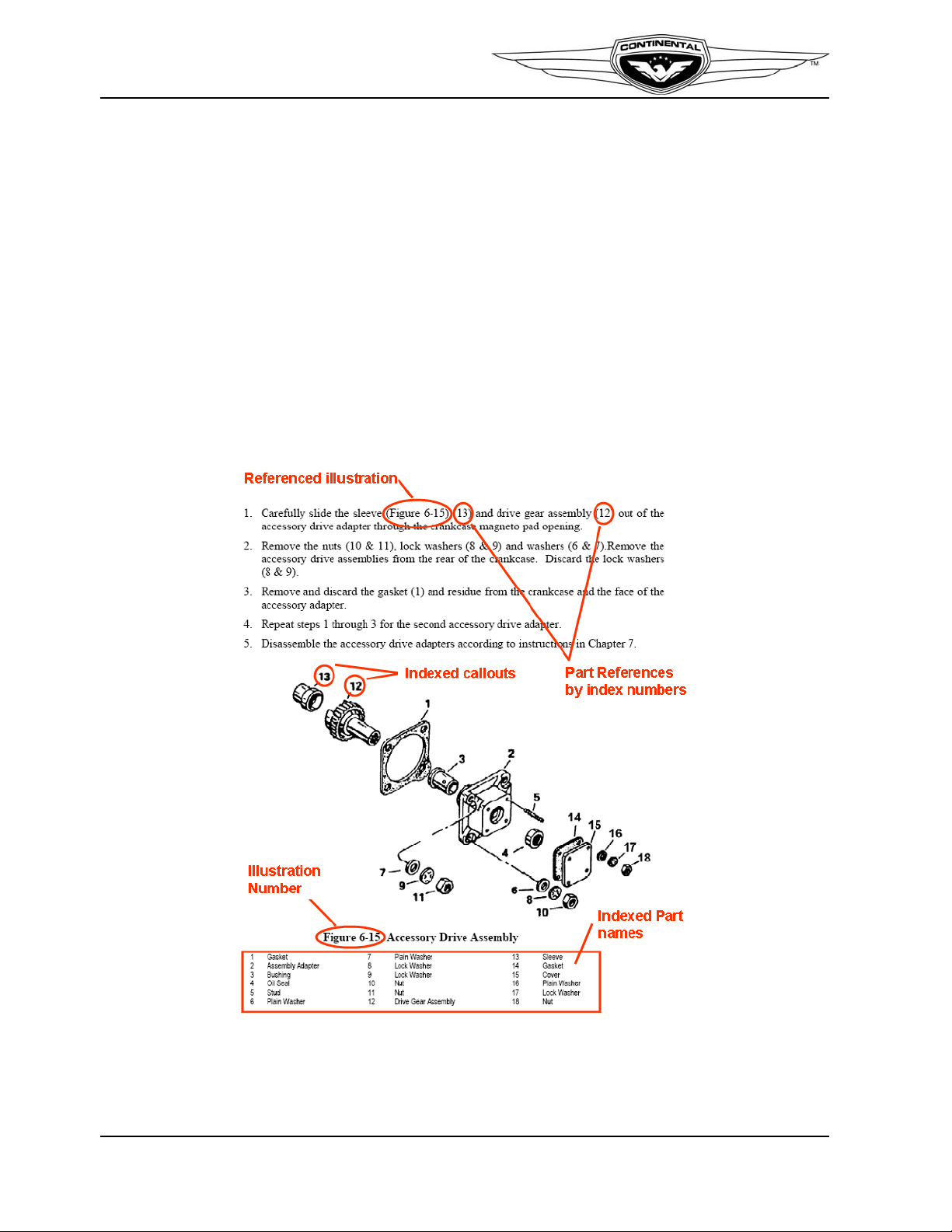
Exploded assembly illustrations accompany instructions throughout the manual. Parts in
illustrations (Figure 1-1.) are identified with numerical callouts (indexes). Corresponding
parts listings follow the illustrations for reference. The first time instructions refer to an
illustration, the figure number is identified in parentheses, followed by the callout. In
subsequent parts references, only the callout will be specified unless the referenced
illustration changes.
WARNING
Continental Motors ICAs are applicable only to Continental
Motors engines conforming to the approved, type certified
engine model configuration. Continental Motors ICAs must not
be used for aftermarket parts.
Figure 1-1. Figure and Index Reference
1-2 IO-240 Series Engine Installation & Operation Manual
31 October 2011
Page 17

1-2. Publications
1-2.1. Service Documents
Continental Motors may issue Service Documents in one of six categories ranging from mandatory
(Category 1) to informational (Category 6). Definitions of the categories are listed below:
NOTE: Upon FAA approval, Continental Motors publishes service
documents for immediate availability on our web site. The service
document cover page indicates the engine models affected by the service
document. Service documents may alter or replace manufacturer’s ICAs.
Insert a copy of applicable Service Documents in affected manuals until
the service document instructions are incorporated in the manual, or the
service document is cancelled or superseded.
1Procedure
Category 1: Mandatory Service Bulletin (MSB)
Used to identify and correct a known or suspected safety hazard which has b een incorporated in whole or in
part into an Airworthiness Directive (AD) issued by the FAA or have been issued at the direction of the FAA
by the manufacturer requiring compliance with an already-issued AD (or an equivalent issued by another
country’s airworthiness authority). May contain updates to Instructions for Continued Airworthiness (ICAs)
to address a safety issue.
Category 2: Critical Service Bulletin (CSB)
This category identifies a condition that threatens continued safe operation of an aircraft, persons or property
on the ground unless some specific action (inspection, repair, replacement, etc.) is taken by the owner or
operator. Documents in this category are candidates for incorporation into an FAA Airworthiness Directive.
May contain updates to ICAs to address a safety issue.
Introduction
Category 3: Service Bulletin (SB)
Information which the product manufacturer believes may improve the i nherent safety of an aircraft or
aircraft component; this category includes the most recent updates to ICAs.
Category 4: Service Information Directive (SID)
The manufacturer directs the owner/operator/mechanic in the use of a product to enhance safety,
maintenance or economy. May contain updates to ICAs in the form of maintenance procedures or
specifications.
Category 5: Service Information Letter (SIL)
This category includes all information (not inclu ded in categories 1 through 4) that may be useful to the
owner/operator/technician. May contain updates to ICAs for optional component installations, which are not
covered in the Applicable Operator, Maintenance, or Overhaul Manuals.
Category 6: Special Service Instruction (SSI)
This category is used to address an issue limited to specific model and/or serial number engines. We will
distribute SSI notification directly to the affected engine’s owners.
service document set but will be made available through our Customer Service Department to owners of the
affected engines only . An SSI may update the applicable engine’s Instructions for Continued Airworthiness.
SSIs will not be included in the general
IO-240 Series Engine Installation & Operation Manual 1-3
31 October 2011
Page 18

Introduction
1-2.2. Related Publications
The table below lists related publications, source, and accessibility relevant to IO-240
Series engine installation and operation.
WARNING
Use only the latest revision of all publications. Using superseded
information may jeopardize engine airworthiness
Table 1-1. Related Publications
Supplied
With
Publication
Engine
Maintenance and Overhaul Manual (M-6) Yes
S-20/S-200 Magneto Service Manual (X42002) Yes Yes Yes
Service Documents No Yes Yes
Parts Catalog No Yes (view only)No
Available
download at
web site
1
Yes
Printed
Manual
Available
for
Purchase
Yes
1. Our web site (http://continentalmotors.aero) provides 24-hour access to engine technical data via the Internet. If you are an internet service subscriber, you can access our web site to confirm and review the latest revision of this manual. If you have not subscribed to internet service and are using printed manuals, contact using the “Contact Information” on page 8. to confirm you have the latest revision of
the manual.
1-4 IO-240 Series Engine Installation & Operation Manual
31 October 2011
Page 19

1-2.3. Publication Access
Contact an authorized Continental Motors distributor to discuss service subscription
options and pricing or visit the Continental Motors web site. Printed technical publications
may be ordered through authorized Continental Motors distributors or via the Internet at
http://continentalmotors.aero.
1-2.4. Publication Changes
The instructions in this manual represent the best and most complete information available
at the time of publication. Product or process improvements may trigger changes to
existing product design specifications or procedures contained in publications. As new
technical information becomes available, Continental Motors will make the information
available to the customer.
New information may be contained in Continental Motors
service documents. Service documents applicable to engines
and accessories within the scope of this manual must be
complied with as defined in these documents. This manual and
other related publications noted herein constitute the ICAs
prepared by Continental Motors and accepted by the FAA.
Introduction
WARNING
Continental Motors releases publication changes in the form of either change pages or
complete publication revisions, depending upon the extent of change. Service Documents
may supplement or replace technical information contained in one publication or an entire
series of publications. Such Service Documents represent a change to the published ICA
until the individual publications incorporate the latest technical information.
1-2.4.1. Update/Change Distribution
Document updates are available on our web site upon notification of FAA document
approval. Printed publication subscribers receive printed changes and revisions as they are
released.
Document revisions are released if the update changes more than 50% of the contents of a
publication. Revisions replace the previous version of a publication from cover to cover.
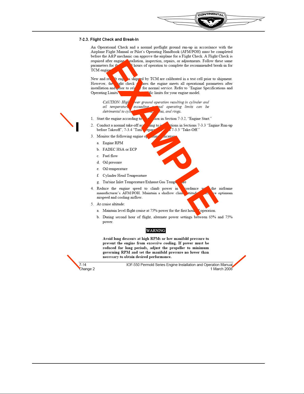
Minor corrections are released as change pages to the original publication, identified with
a change number and effective change date in the page footer. Information on the page that
changed from the previous edition is identified by a vertical, six-point black line (Figure
1-2.), referred to as a “change bar” in the outside margin of the page. A change page
replaces only the previous edition of the affected page.
IO-240 Series Engine Installation & Operation Manual 1-5
31 October 2011
Page 20
Introduction
Change Bar
Change
Number
Change
Date
Change Bar
Change
Number
Change
Date
Change Bar
Change
Number
Change
Date
1-6 IO-240 Series Engine Installation & Operation Manual
Figure 1-2. Change Page Identification
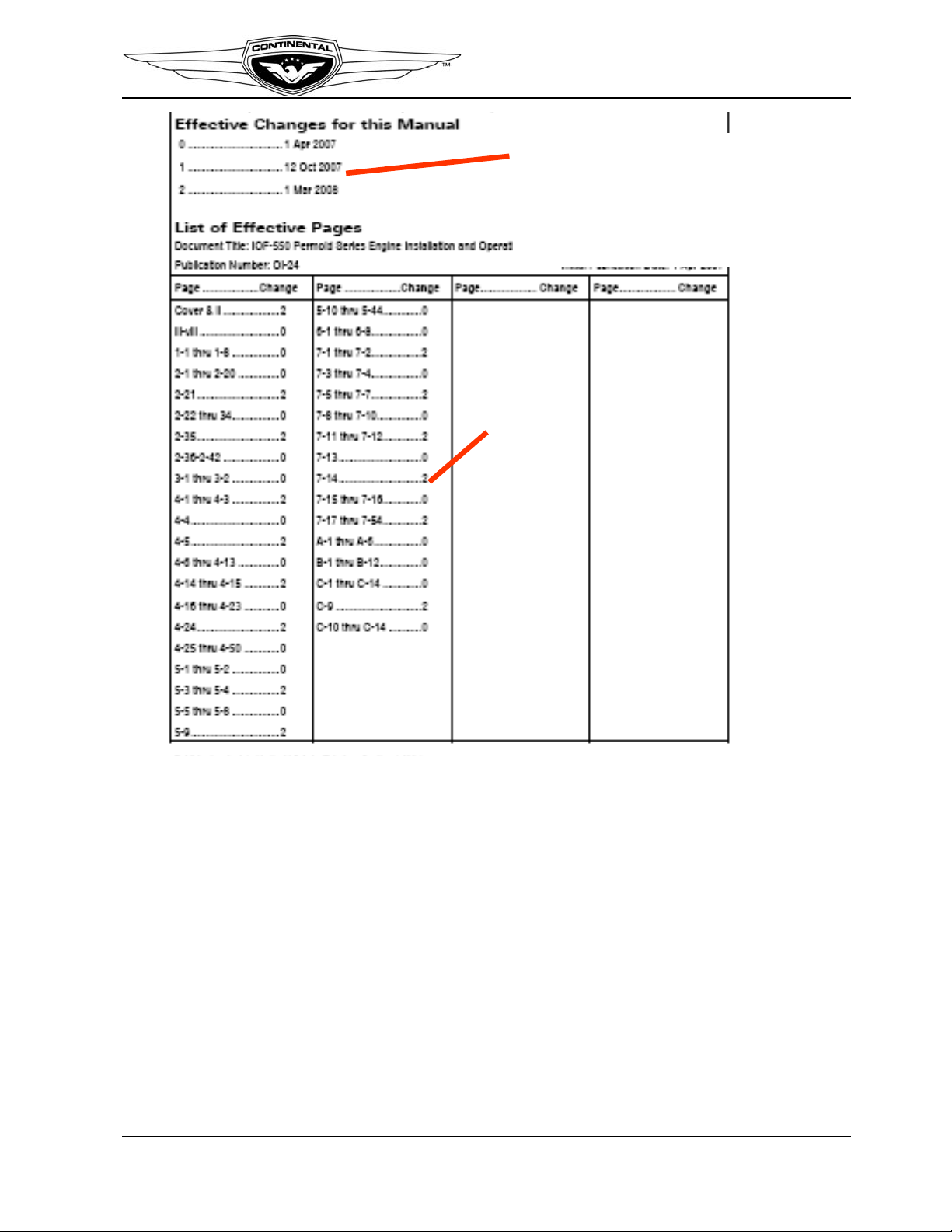
Page A of the manual contains the original publication date and an itemized list of changes
issued for the technical manual (Figure 1-3.). If change pages are issued for the manual,
the change will be identified, with an effective date under the heading “Effective Changes
for This Manual.” The list of effective pages, itemizes the pages in each section, by
change number. Original pages are designated by a 0 in the List of Effective Pages
“Change” column.
31 October 2011
Page 21
Introduction
Effective Manual
Changes and
Change Dates
Itemized List
of Effective
Pages
Effective Manual
Changes and
Change Dates
Itemized List
of Effective
Pages
Figure 1-3. List of Effective Pages
1-2.4.2. Suggestions and Corrections
Continental Motors solicits and encourages user comments regarding suggested changes
to this manual. Direct recommended changes or questions to the attention of
“Publications” at the address listed in Section 1-3, “Contact Information” or send
comments via email to CM.techpubs@continental.aero.
Notify our Customer Service Department immediately, using our toll-free number, if you
discover incorrect information which adversely affects safety.
IO-240 Series Engine Installation & Operation Manual 1-7
31 October 2011
Page 22

Introduction
1-3. Contact Information
Continental Motors is available to answer technical questions and encourages suggestions
regarding products, parts, or service. If customers have an inquiry or require technical
assistance, they should contact their local Continental Motors distributor or field
representative. To contact a factory representative, refer to the contact information below:
Continental Motors, Inc.
P. O. Box 90
Mobile, AL 36601
Customer Service:
Toll free within the Continental United States: 1-888-826-5465
International: 1-251-438-8299
Internet: http://continentalmotors.aero.
1-8 IO-240 Series Engine Installation & Operation Manual
31 October 2011
Page 23

Chapter 2 . Engine Description
2-1. General Engine Description
IO-240 engines are four-cylinder, four-stroke reciprocating aircraft engines. IO-240-A &
B engines are designed for fixed pitch, ground adjustable, or electric constant speed
propellers. There is no provision for a hydraulic propeller governor. Cylinder
displacement of 240 cubic inches is achieved with a 4.44 inch bore and a 3.88 inch stroke.
IO-240 series engines are equipped with continuous flow fuel injection and a either an
updraft or a downdraft induction system, depending on the engine model.
IO-240 series engines are designed with a wet sump, positive displacement oil pump
installed in the accessory case. When properly maintained, under normal operating
conditions, the desired oil pressure is maintained by a pressure relief valve located in the
accessory case. Engine cranking is accomplished by a geared starter mounted on the
accessory case.
A gear driven alternator is installed on the accessory case. The engine is equipped with
two gear-driven magnetos. The downdraft exhaust system is supplied by the airframe
manufacturer.
IO-240 series engines have a doweled, six bolt propeller flange.
Engine Description
IO-240 Series Engine Installation & Operation Manual 2-1
31 October 2011
Page 24
Engine Description
I O-240-B1
Specification Number
Model Identifier
Cubic Inch Displacement
Horizontally Opposed Cylinders
Fuel Injected
B
Shipping Designation
I O-240-B1
Specification Number
Model Identifier
Cubic Inch Displacement
Horizontally Opposed Cylinders
Fuel Injected
B
Shipping Designation
4
2
3
1
4
2
3
1
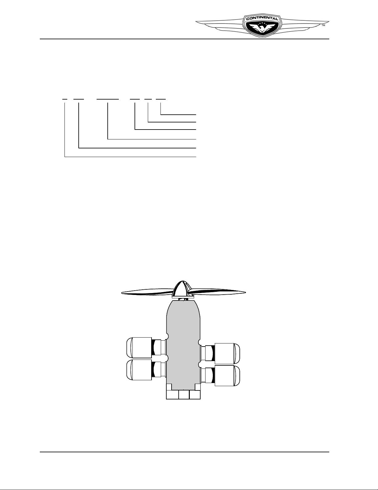
2-1.1. Engine Model Number Definition
The description of each alphanumeric character in the engine model number is given
below for the example engine model number IO-240-B1B (Figure 2-1).
Figure 2-1. Engine Model Definition
2-1.2. Cylinder Number Designations
Refer to Figure 2-2:
• The front of the engine is the end closest to the propeller and the rear of the engine is
the accessory end.
• V iewed from the rear of the engine, the left-side cylinders are designated by even num-
bers 2-4, with Cylinder 2 being closest to the rear.
• The right side cylinders have odd number sequential designation 1-3, with Cylinder 1
being closest to the rear.
• Firing order of the engine is 1-3-2-4.
Figure 2-2. Cylinder Number Designation
2-2 IO-240 Series Engine Installation & Operation Manual
31 October 2011
Page 25
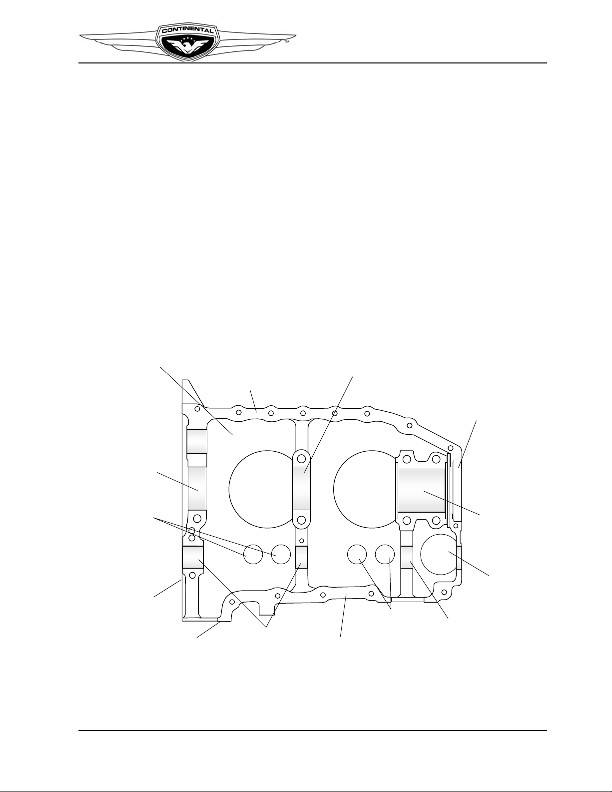
2-2. Detailed Engine Description
REAR CRANKSHFT
BEARING BORE
Cyl #2 Cyl #4
2-4 OR L/H
CRANKCASE HALF
INTERMEDIATE
CRANKSHAFT BEARING BORE
BACKBONE
CRANKSHAFT NOSE
SEAL LAND
FRONT
CRANKSHAFT
BEARING BORE
CAMSHAFT
BEARING BORE
TAPPET
GUIDES
SPINE BELOW
CAMSHAFT
CAMSHAFT
BEARING BORE
OIL SUMP
MOUNT FLANGE
ACCESSORY CASE
MOUNT FLANGE
TAPPET
GUIDES
FUEL
PUMP
MOUNTING
PAD
REAR CRANKSHFT
BEARING BORE
Cyl #2 Cyl #4
REAR CRANKSHFT
BEARING BORE
Cyl #2 Cyl #4
2-4 OR L/H
CRANKCASE HALF
INTERMEDIATE
CRANKSHAFT BEARING BORE
BACKBONE
CRANKSHAFT NOSE
SEAL LAND
FRONT
CRANKSHAFT
BEARING BORE
CAMSHAFT
BEARING BORE
TAPPET
GUIDES
SPINE BELOW
CAMSHAFT
CAMSHAFT
BEARING BORE
OIL SUMP
MOUNT FLANGE
ACCESSORY CASE
MOUNT FLANGE
TAPPET
GUIDES
FUEL
PUMP
MOUNTING
PAD
2-2.1. Crankcase
Two aluminum alloy castings are joined along the vertical center plane to form the
crankcase. The individual castings (with studs and inserts) are referred to as the “left
crankcase” and “right crankcase.” The crankcase provides a tight enclosure, sufficiently
rigid to support the crankshaft, camshaft and bearings, with oil galleries for lubrication.
Bosses molded in the crankcase castings are line bored in the assembled crankcase halves
to form bearings for the camshaft and saddles for precision crankshaft main bearing
inserts. Guides are bored through lateral bosses for hydraulic tappets. There are six studs
and two through-bolts for attaching cylinder base flanges. The fuel pump mounting pad is
located on the left crankcase half, forward of Cylinder 4 (Figure 2-3).
Cylinder mounting pads on the left and right crankcase are offset to permit each crankpin
to transmit the rotational force to the piston through the connecting rod. The crankcase
interior is vented by a breather assembly comprised of a tube and baffle assembly with a
side extension for a hose attachment. The breather assembly is pressed into a boss on the
top side of the right crankcase half, forward of Cylinder 3.
Engine Description
Figure 2-3. IO-240 Crankcase Features
IO-240 Series Engine Installation & Operation Manual 2-3
31 October 2011
Page 26

Engine Description
Starter
Alternator
Crankshaft
Camshaft
Fuel Pump &
Vacuum
Pump Driv e
Shaft
Camshaft
GearTachometer
Drive Shaft Oil Pump
Drive Gear
Oil Pump
Driven Gear
Starter
Alternator
Crankshaft
Camshaft
Fuel Pump &
Vacuum
Pump Driv e
Shaft
Camshaft
GearTachometer
Drive Shaft Oil Pump
Drive Gear
Oil Pump
Driven Gear
2-2.2. Engine Drive Train
The engine drive train (Figure 2-4) consists of the crankshaft, camshaft and drive gears.
The crankshaft has a propeller flange at one end to attach a propeller for thrust. The starter
gear meshes with the outer teeth of the rear crankshaft gear to turn the crankshaft until the
fuel mixture in the cylinder is ignited by the spark plugs. A drive gear at the rear end of the
crankshaft interfaces with a gear mounted on the rear end of the camshaft to synchronize
intake and exhaust valve movement and magneto rotation, as well as supply driving force
to the gear driven alternator. The oil pump driven gear, along with the optional tachometer
drive are gear driven by the inner row of teeth on the camshaft. The engine driven fuel
pump, and the optional vacuum pump drive are driven by a gear on the forward end of the
camshaft.
Figure 2-4. Engine Drive Train
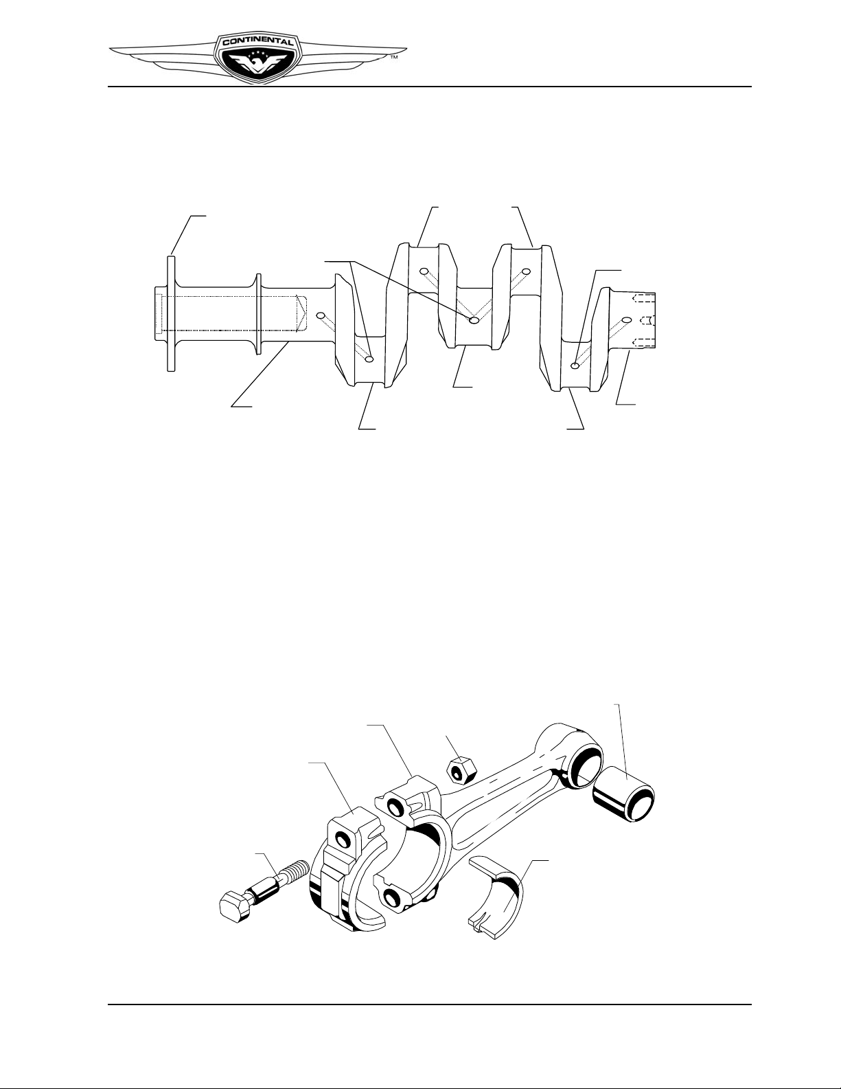
2-2.2.1. Crankshaft
The crankshaft (Figure 2-5) is an aircraft quality steel forging with three machined, main
journals supported by precision-bearing inserts in each of the three bearing saddles
machined in the crankcase. Four machined rod journals provide attachment of the
connecting rod assemblies.
The crankshaft gear is indexed on the crankshaft by a dowel and secured by machined
bolts. A neoprene oil seal over the crankshaft flange is seated between the crankcase
castings in the front shaft exit area, and is sealed to the crankshaft by a helical spring
inside the seal's cavity.
2-4 IO-240 Series Engine Installation & Operation Manual
31 October 2011
Page 27
Engine Description
CRANKSHAFT
FLANGE
FRONT MAIN
JOURNAL
ROD JOURNAL
ROD JOURNAL ROD JOURNAL
REAR MAIN
JOURNAL
MIDDLE MAIN
JOURNAL
OIL
PASSAGE
#1
#2
#3
#4
OIL
PASSAGE
CRANKSHAFT
FLANGE
FRONT MAIN
JOURNAL
ROD JOURNAL
ROD JOURNAL ROD JOURNAL
REAR MAIN
JOURNAL
MIDDLE MAIN
JOURNAL
OIL
PASSAGE
CRANKSHAFT
FLANGE
FRONT MAIN
JOURNAL
ROD JOURNAL
ROD JOURNAL ROD JOURNAL
REAR MAIN
JOURNAL
MIDDLE MAIN
JOURNAL
OIL
PASSAGE
#1
#2
#3
#4
OIL
PASSAGE
NOTE: Some older models use castellated nut with cotter pin
SPIRAL LOCK NUT
BRONZE BUSHING
CONNECTING ROD
CONNECTING ROD
CAP
ROD BOLT
SHELL
BEARING
The flange type crankshaft has a propeller mount flange forged on the front end with six
tapped bushings pressed into holes spaced equally around the flange. Six bolts, screwed
into the shaft flange bushings, clamp the propeller between a loose front flange and the
shaft flange.
Figure 2-5. Crankshaft
2-2.2.2. Connecting Rods
The connecting rods halves (Figure 2-6) are machined from a single forging of aircraft
quality steel and cut into two pieces, splitting the center of the larger opening of the
connecting rod assembly. The resulting pieces, called the rod and cap are fitted with a two
piece bearing and attach to the crankpin or rod journal with special bolts and nuts.
The portion of the rod between the rod and the crankpin and piston pin ends is called the
“I” beam. A split steel-backed bronze bushing is pressed into the piston pin end and
machined for a precision pin-to-bushing fit.
Figure 2-6. Connecting Rod
IO-240 Series Engine Installation & Operation Manual 2-5
31 October 2011
Page 28
Engine Description
FRONT REAR
#4 EXH #3 EXH #2 EXH #1 EXH
#3 & 4
INTAKE
#1 & 2
INTAKE
M/J
C/L C/L C/L C/L C/L C/L
M/J M/J
C/L - CAM LOBE
M/J - MAIN JOURNAL
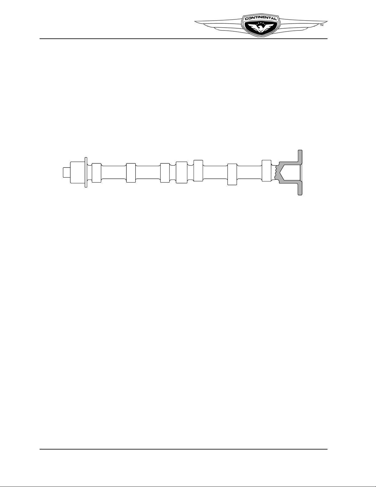
2-2.2.3. Camshaft
The camshaft forging is machined on three main journals, six cam lobes and the gear
mount flange at the rear of the camshaft (Figure 2-7). The lobes and journals are ground
and hardened. Camshaft main journals are supported in the crankcase by machined
bearing saddles. Hydraulic tappets move inward and outward in their bores, following the
eccentric shape of the cam lobes. Four unequally spaced bolts secure the gear to the
camshaft and ensure proper positioning, locating the gears' timing mark in relation to the
cam lobes. The camshaft gear has internal teeth to drive the alternator. A front-mounted
bevel gear drives the accessory drive bevel gear and fuel pump through a common shaft.
Figure 2-7. Camshaft
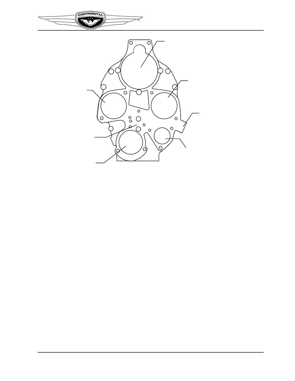
2-2.3. Accessory Case
The accessory case (Figure 2-8) aluminum alloy casting is attached to the rear of the
engine crankcase, aligned with crankcase dowels. The accessory case is secured to the
crankcase by crankcase studs and various attaching hardware. Accessory mount pads on
the rear surface are machined in one plane parallel to the machined parting flange which
surrounds the front side of the casting. Mounting pads for the magnetos, alternator cover,
starter, tachometer drive, oil filter adapter, oil pressure relief valve and an oil suction
screen boss are provided. The accessory case casting has two holes above and three studs
to attach the starter. A mounting pad is provided for a permanent oil screen housing. In
lieu of the oil screen housing, an oil filter adapter, with a screw-on type oil filter is also
available.
The oil pump housing is machined into the internal portion of the accessory case. A
machined, threaded boss is located on the lower right side of the accessory case for
installation of a non-adjustable oil pressure relief valve. Oil pump gear chambers are
machined in the interior of the accessory case. The oil pump drive gear shaft hole is
machined in-line with the camshaft and the driven gear shaft hole is directly above it.
A semicircular opening at the accessory case bottom is a machined threaded hole to
accommodate installation of the oil suction tube. Passages cast into the accessory case
allow oil to flow from the oil suction tube to the oil pump gears, pressure relief valve, and
main oil gallery. The tachometer drive shaft is the slotted end of the oil pump driven gear
shaft.
2-6 IO-240 Series Engine Installation & Operation Manual
31 October 2011
Page 29
Engine Description
STARTER MO UNTING
PAD
MAGNETO MOUNTIN G
PAD
TACH DRIVE
MOUNTING
PAD
ALTERNATOR
MOUNTING
PAD
OIL SCREEN
HOUSING
MOUNTING
PAD
OIL PRESSURE
HOUSING
MAGNETO
MOUNTING
PAD
RELIEF VALVE
2-2.4. Cylinders
The IO-240 engine have four, horizontally-opposed, air cooled cylinders, two on the left
side and two on the right side of the engine. The cylinders, pistons and valve drive train
provide the momentum to sustain crankshaft movement. Aviation fuel and air are drawn
into a cylinder during the intake stroke, compressed by the piston during the compression
stroke and then ignited by a high intensity spark from each spark plug (two per cylinder).
As the mixture is ignited, the expanding gases force the piston to move inward toward the
crankshaft during the power stroke.
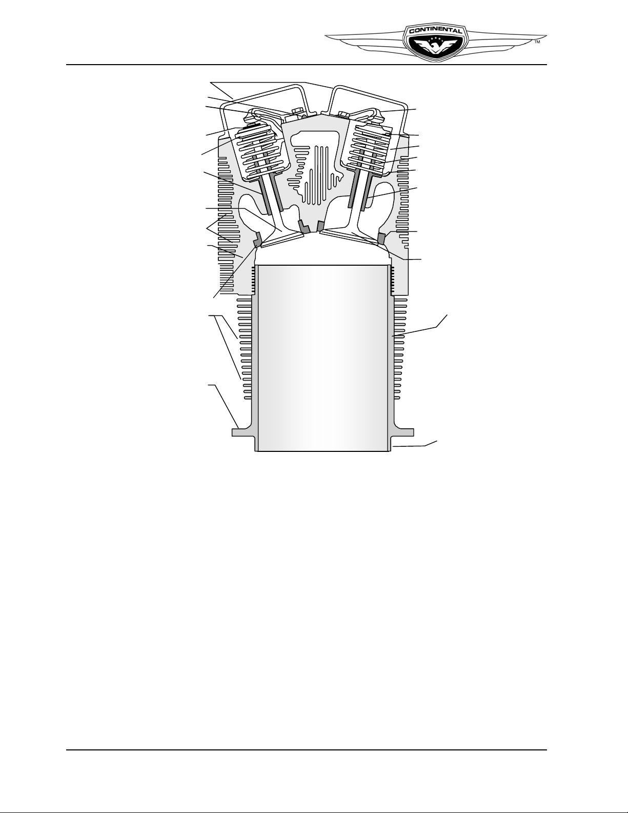
The head and barrel assembly (Figure 2-9) consists of externally finned aluminum alloy
head casting and a steel, nitrided cylinder barrel for wear resistance. Helical coil thread
inserts are installed in upper and lower spark plugs holes. A rotocoil assembly retains two
concentric springs surrounding the exhaust valve and is locked to the stem by tapered,
semi-circular keys which engage grooves around the valve stems. An outer retainer holds
two concentric springs which surround the intake valve and is locked to the stem by
tapered, semi-circular keys which engage grooves on the stem.
IO-240 Series engines use a cross flow cylinder head design. The intake ports are located
on top of the cylinder head while the exhaust ports are located below. There are separate
intake and exhaust valve rocker covers made from zinc-plated stamped sheet steel. This
cylinder design is used in conjunction with a Balanced Induction System mounted above
the engine.
Figure 2-8. Accessory Case Features
IO-240 Series Engine Installation & Operation Manual 2-7
31 October 2011
Page 30
Engine Description
ROCKER SHAFT
ROCKER ARM
VALVE RETAIN ER
KEYS
ROTOCOIL
EXHAUST
VALVE GUIDE
OUTER SPRING
INNER SPRING
SPRING SEAT
INTAKE VALVE GUIDE
INTAKE VALVE
SEAT INSERT
INTAKE VALVE
CYLINDER BARREL
EXHAUST
VALVE
COOLING FINS
CYLINDER HEAD
CYLINDER BARREL
COOLING FINS
CYLINDER BASE
FLANGE
CYLINDER SKIRT
ROCKER COVER
RETAINER
EXHAUST
VALVE
SEAT
INSERT
THRUST WASHER
(ONE ON EACH SIDE
OF EACH ROCKER ARM)
Figure 2-9. Cylinder Features
2-8 IO-240 Series Engine Installation & Operation Manual
31 October 2011
Page 31

2-2.4.1. Pistons
PISTON PIN
MANGANESE PHOSPHATE COATING
GRAPHITE COATED SKIRT
1
ST
COMPRESSION
RING
2
ND
COMPRESSION
RING
OIL CONTROL
RING
OIL SCRAPER
RING
Pistons (Figure 2-10) are aluminum alloy castings with a steel insert cast into the top ring
groove. The skirts are solid and have cylindrical relief cuts at the bottom. Pistons have
three ring grooves above the piston pin bore and one ring groove below. Compression
rings are installed in the top and second grooves. The groove below the piston pin bore
contains an oil scraper . A center grooved and slotted oil control ring is installed in the third
groove which has six oil drain holes to the interior. Weight differences are limited to ½
ounce between opposing cylinders bays. Piston pins are full floating with permanently
pressed-in aluminum end plugs.
Engine Description
2-2.4.2. Hydraulic Valve Tappets
Figure 2-10. Piston Features
The hydraulic valve tappet (lifter) provides an interface between the camshaft lobe and the
remaining valve train. Lifters ride on the eccentric cam lobes, opening and closing the
intake and exhaust valves mechanically via push rod tubes and rocker arms, converting the
cam lobe profile into a linear movement for intake and exhaust valves actuation. The
hydraulic mechanism inside the hydraulic mechanism maintains zero clearance between
the valve and actuating components.
IO-240 Series Engine Installation & Operation Manual 2-9
31 October 2011
Page 32

Engine Description
AA
OIL
SUCTION
TUBE
OIL PRESSURE
RELIEF VALVE
CRANKSHAFT
BEARINGS
CAMSHAFT
BOSS
INTAKE
EXHAUST
PUSHROD
HOUSING
PUSHROD
HYDRAULIC
LIFTERS
OIL SUMP
OIL PUMP GEARS
OIL FILTER
SCREEN
OIL COOLER
ADAPTER
OIL
SUCTION
TUBE
OIL PRESSURE
RELIEF VALVE
CRANKSHAFT
BEARINGS
CAMSHAFT
BOSS
INTAKE
EXHAUST
PUSHROD
HOUSING
PUSHROD
HYDRAULIC
LIFTERS
OIL SUMP
OIL PUMP GEARS
OIL FILTER
SCREEN
OIL COOLER
ADAPTER
2-2.5. Lubrication System
The engine lubrication system (Figure 2-11 and Figure 2-12) delivers lubricating oil
throughout the engine to various bearings, bushings, and engine components. The wet
sump lubrication system consists of an internal engine-driven oil pump, a fixed, nonadjustable pressure relief valve, an oil sump and oil sensing ports. Various optional oil
cooler adapters allow connection of an optional remote mounted oil cooler.
2-10 IO-240 Series Engine Installation & Operation Manual
Figure 2-11. IO-240-A Lubrication
31 October 2011
Page 33

Engine Description
BB
OIL
SUCTION
TUBE
OIL PRESSURE
RELIEF VALVE
CRANKSHAFT
BEARINGS
CAMSHAFT
BOSS
INTAKE
EXHAUST
PUSHROD
HOUSING
PUSHROD
HYDRAULIC
LIFTERS
OIL SUMP
OIL PUMP GEARS
OIL FILTER AND
BYPASS
ASSEMBLY
OIL COOLER
ADAPTER
OIL
SUCTION
TUBE
OIL PRESSURE
RELIEF VALVE
CRANKSHAFT
BEARINGS
CAMSHAFT
BOSS
INTAKE
EXHAUST
PUSHROD
HOUSING
PUSHROD
HYDRAULIC
LIFTERS
OIL SUMP
OIL PUMP GEARS
OIL FILTER AND
BYPASS
ASSEMBLY
OIL COOLER
ADAPTER
2-2.5.1. Oil Pump
IO-240 Series Engine Installation & Operation Manual 2-11
31 October 2011
Figure 2-12. IO-240-B Lubrication
The engine-driven, gear type oil pump (Figure 2-13) is a positive displacement pump that
consists of two meshed steel gears that revolve inside the oil pump cavity machined in the
accessory case. The camshaft drives the oil pump drive gear, which drives the oil pump
driven gear. The oil pump driven gear is supported by a shaft pressed into the accessory
case and the oil pump cover plate. The oil pump drive gear shaft is supported by bushings
pressed into the accessory case. The oil pump gear shaft incorporates provisions to drive a
mechanical tachometer.
The oil pump housing and oil pump gear chambers are machined in the interior of the
accessory case. The oil pump drive gear shaft bore is machined in-line with the camshaft;
the driven gear shaft rests in the bore directly above the drive shaft.
Page 34

Engine Description
Figure 2-13. Oil Pump
2-2.5.2. Oil Sump
The oil sump body is a welded unit composed of front and rear halves of pressed sheet
steel. A thick mounting flange ring, an oil filler neck, and drain plug boss are welded to
the body to complete the assembly. The oil sump plug boss has provisions for safety
wiring the plug. A bracket welded to the neck attaches the oil sump to a stud in the lower
crankcase engine mounting arm. At the neck of the oil filler pipe, a locking device retains
the dip stick. The dipstick is marked in quarts to the full mark.
2-2.5.3. Oil Pressure Relief Valve
A machined, threaded boss is located on the lower right side of the accessory case for
installation of a non-adjustable oil pressure relief valve. Its passages are connected to the
oil pump outlet passage. This valve opens when the oil pump pressure exceeds the
specified operating limit and directs oil back to the oil sump.
2-2.5.4. Oil Cooler Adapter
The IO-240 engine features an oil cooler adapter (Figure 2-11) or oil cooler/filter adapter,
located on the lower 2-4 side crankcase. The IO-240-A (Figure 2-14) and B oil cooler
adapters (Figure 2-15 and Figure 2-16) function the same but differ physically. Each
incorporates a bypass valve in the event of a clogged oil cooler and have provisions for the
attachment of an externally-mounted oil cooler, with bosses for oil temperature and
pressure sensors. The oil cooler/filter adapter offers the same functions as the oil cooler
adapters with the added feature of a threaded boss for a spin on oil filter.
2-12 IO-240 Series Engine Installation & Operation Manual
31 October 2011
Page 35

Figure 2-14. IO-240-A Oil Cooler Adapter
AA
BB
BB
OIL BY-PASS FLOW
PLUG
OIL BY-PASS
VALVE
PLUG
OIL TEMP.
PORT
OIL FLOW BACK
TO ENGINE
OIL PRESSURE PORT
OIL FLOW OUT
TO EXTERNAL
OIL COOLER
OUT
OIL BY-PASS FLOW
PLUG
OIL BY-PASS
VALVE
PLUG
OIL TEMP.
PORT
OIL FLOW BACK
TO ENGINE
OIL PRESSURE PORT
OIL FLOW OUT
TO EXTERNAL
OIL COOLER
OUT
OUT
IN
PR
T
EM
P
OUT
IN
PR
T
EM
P
OUT
IN
PR
T
EM
P
OUT
IN
OUT
IN
PR
T
EM
P
OUT
IN
PR
T
EM
P
OUTOUT
ININ
Engine Description
Figure 2-15. IO-240-B Oil Cooler Adapter
IO-240 Series Engine Installation & Operation Manual 2-13
31 October 2011
Figure 2-16. IO-240-B Oil Cooler/Filter Adapter
Page 36

Engine Description
S 6 R N -1201
Model Number
S-20 Serles
21: Dog-Ear Mount, Impulse Coupled
25: Deep Flange Mount, Impulse Coupled
S-200 Serles
200: Dog Ear Mount, With Retard Breaker
201: Deep Flange Mount, With Retard Breaker
204: Dog Ear Mount
205: Deep Flange Mount
S-1200 Serles
1201: Deep Flange Mount, With Retard Breaker
1205: Deep Flange Mount
1208: Short Flange Mount, With Retard Breaker
1209: Short Flange Mount
1225: Deep Flange Mount, Impulse Coupled
1227: Short Flange Mount, Impulse Coupled
1251: Pressurized Version of 1201
1255: Pressurized Version of 1205
1258: Pressurized Version of 1208
1259: Pressurized Version of 1209
D-3000 Serles
3000: Impulse Coupled
3200: With Retard Breaker
Magneto Configuration
S = Single Type Magneto:
one drive, one output distributor
D = Dual Type Magneto:
one drive, two output distributors
Cylinders Fired
4 = Four Cylinders
6 = Six Cylinders
8 = Eight Cylinders
Rotatlon
(Viewed Looking in to Drive End)
L = Left (counterclockwise)
R = Right (clockwise)
Designator
N = Scintilla Design
SC = Short Cover
Suffix: S-20 and S-200 Series Only
T= Tachometer Breaker Points
P= Pressurized
2-2.6. Ignition System
Two magnetos, installed on the aft side of the accessory case use magneto drive adapters
to interface with the crankshaft gear. IO-240 Series engines are fitted with either
Champion (Slick) 4301or Continental Motors S4LSC-21 series magnetos, designed to
provide ignition for four cylinder aircraft engines. The Continental Motors magneto model
number identifies the key features of each magneto model, as shown in Figure 2-17. The
engine firing order (Figure 2-18) is determined by the camshaft lobes; magneto firing
order is sequential from the number one position and must be synchronized to the
crankshaft.
To obtain the retard spark necessary for starting, the magnetos may be equipped with a
starting vibrator for a shower of sparks type ignition or employ impulse couplings within
the magneto. Impulse couplings rotate the magneto between impulse trips faster than
engine cranking speed, thus generating a better spark for starting the engine and
automatically retard the spark during engine cranking. After engine start, impulse
couplings function as normal magneto drive couplings.
2-14 IO-240 Series Engine Installation & Operation Manual
Figure 2-17. Continental Motors Magneto Part Number Structure
31 October 2011
Page 37

Engine Description
7
7
%
%
7
7
%
%
(1*,1(),5,1*25'(5
0$*1(72),5,1*25'(5
5,*+70$*1(72
72/()7
0$*1(72
6:,7&+
725,*+7
0$*1(72
6:,7&+
/()70$*1(72
³
3´ /(
$
'
7
2
5
4
8
(
,
1
/
%
6
³
3´ /(
$
'
7
2
5
4
8
(
,
1
/
%
6
³3´ /($'
72548(
,1/%6
³3´ /($'
72548(
,1/%6
7
7
%
%
7
7
%
%
(1*,1(),5,1*25'(5
0$*1(72),5,1*25'(5
5,*+70$*1(72
72/()7
0$*1(72
6:,7&+
725,*+7
0$*1(72
6:,7&+
/()70$*1(72
Figure 2-18. Continental Motors Ignition Distribution
Figure 2-19. Slick Ignition Distribution
IO-240 Series Engine Installation & Operation Manual 2-15
31 October 2011
Page 38

Engine Description
2-2.7. Fuel System
The Fuel System (Figure 2-20) is composed of an engine-driven fuel pump, a fuel
manifold valve, an induction system throttle body and fuel injector assemblies. The multiport, continuous flow fuel injection system controls fuel flow to match engine
requirements. The fuel metering unit/throttle controls the amount of intake air admitted
through the intake manifold and meters the proportionate amount of fuel to the fuel
manifold valve.
Figure 2-20. IO-240 Standard Fuel Injection System
2-2.7.1. Fuel Pump
An engine-driven, positive displacement fuel pump (Figure 2-21) delivers fuel to the fuel
injectors. Fuel enters the fuel pump at the well of the swirl chamber where the fuel is
centrifuged and the liquid is separated from fuel vapor. The liquid fuel is directed to the
fuel pump blades. The fuel pump blades force the fuel to the fuel pump outlet through
various fittings, and fuel lines to the fuel manifold valve.
The fuel pump is directly driven at the same speed as the crankshaft; fuel flow and
pressure vary directly with engine speed. An adjustable relief valve maintains pump flow
and pressure for the lower engine speeds, while an adjustable orifice controls fuel pump
2-16 IO-240 Series Engine Installation & Operation Manual
31 October 2011
Page 39

Engine Description
PATH TO
RELIEF VALVE
FUEL INLET
STOP PIN
VAPOR RETURN
DRY BAY DRAIN
FUEL SUPPLY TO ENGINE
MIXTURE
CONTROL
LOW PRESSURE
RELIEF VALVE
ANEROID
ADJUSTMENT
PATH TO
RELIEF VALVE
FUEL INLET
STOP PIN
VAPOR RETURN
DRY BAY DRAIN
FUEL SUPPLY TO ENGINE
MIXTURE
CONTROL
LOW PRESSURE
RELIEF VALVE
ANEROID
ADJUSTMENT
pressure for the higher engine speeds. This combination of mechanical control circuits
ensures proper pump pressure and delivery for all engine operating speeds.
IO-240-B model engines may be equipped with an altitude compensating fuel pump
which adjusts fuel pressure to compensate for atmospheric variations (Figure 2-22). The
IO-240-B fuel system with altitude compensating fuel pump incorporates a fuel filter
between the fuel pump and fuel manifold valve. From the fuel filter, fuel flows to the fuel
manifold valve and subsequently to the injector nozzles.
Figure 2-21. Standard Fuel Pump
Figure 2-22. Altitude Compensating Fuel Pump
IO-240 Series Engine Installation & Operation Manual 2-17
31 October 2011
Page 40

Engine Description
A check valve on the fuel pump permits the use of an auxiliary electric fuel boost pump
during engine priming and starting (allows the aircraft boost pump to bypass the engine
driven fuel pump) or in the unlikely event of an engine driven fuel pump malfunction.
2-2.7.2. Fuel Injectors
The fuel discharge nozzle is located in the cylinder head. The nozzle outlet is screwed into
a tapped fuel nozzle bore in the cylinder head. The nozzle body has a drilled central
passage with a counterbore at each end. The lower end is the fuel outlet. The upper bore
contains a removable jet for nozzle calibration. Near the top, radial holes connect the
upper counterbore with the outside of the nozzle body for air admission. A shroud is
mounted on the nozzle body and extends over the nozzle body. The nozzle shroud is
sealed to the nozzle body by o-rings. The nozzle shrouds are referenced to upper deck
pressure to provide a positive air pressure differential to insure proper fuel atomization at
all operating parameters.
Nozzles are calibrated in several ranges and tuned to each cylinder position for optimum
balance of engine performance and fuel economy. Each nozzle is identified with the
cylinder position number and flow rate engraved on the nozzle body wrench flats.
Figure 2-23. Fuel Injector
2-2.8. Starter Assembly
Several electric starter motors are approved for use on IO-240 engines, all available starter
configurations mount on the rear of the accessory case. Starter engagement is controlled
by the airframe wiring harness and ignition switch contactor.
2-2.9. Alternator
IO-240 engines incorporate a boss on the rear of the engine accessory case for mounting a
direct drive alternator. A 12 volt, 60 amp gear driven alternator is standard equipment for
current engines. Optional belt-driven and lightweight alternators are available, with
retrofit capabilities to older model specifications.
2-18 IO-240 Series Engine Installation & Operation Manual
31 October 2011
Page 41

The alternator generates electrical current for recharging aircraft batteries and powering
aircraft electrical systems. For a description of the aircraft electrical and charging system,
see the applicable Airframe Manufacturer's Instructions. For a detailed description of
Continental Motors alternators, refer to the Alternator Service Instructions.
2-2.10. Engine Cooling
The engine cylinders are cooled by transferring heat from the cylinder barrel and cylinder
head cooling fins to the surrounding airflow. The airframe engine cowling, baffles, and
baffle seals direct cooling air (which is ram air-induced by the aircraft's forward speed)
evenly around the cylinders. This airflow is regulated by the size of the cooling air inlets
and outlets. Increasing or decreasing outlet size with the use of cowl flaps changes airflow
and is used as an aid in controlling engine operating temperatures.
Engine Description
Figure 2-24. Engine Cooling
IO-240 Series Engine Installation & Operation Manual 2-19
31 October 2011
Page 42

Engine Description
FUEL PUMP
THROTTLE
INDUCTION SYSTEM
FUEL PUMP
THROTTLE
INDUCTION SYSTEM
2-2.11. Induction System
IO-240-A engines feature an updraft induction system. The air throttle is mounted below
the engine. Induction tubes deliver air from the throttle body to the intake ports on top of
the cylinder.
Figure 2-25. IO-240-A Induction System
The IO-240-B downdraft induction system (Figure 2-26), consists of the air throttle and
manifold body mounted on top of the engine. Intake tubes carry induction air from the
manifold to the individual cylinder intake ports. Crossflow design cylinders improve
airflow efficiency through the cylinder head. Air flows from the aircraft air inlet/alternate
air door to the engine cylinders through the Induction System.
Figure 2-26. IO-240-B Crossflow Induction System
2-20 IO-240 Series Engine Installation & Operation Manual
31 October 2011
Page 43

Engine Description
2-3. Engine Specifications and Operating Limits
Table 2-1. IO-240-A Specifications and Operating Limits
General
Model IO-240-A
FAA Type Certificate E7S0
Installation Drawing Number 653200
Compression Ratio 8.5:1
Number of Cylinders 4
Firing Order 1-3-2-4
Time Between Overhaul (TBO) 2000 accumulated hours or 12 years
Bore 4.43 in. 112.7 cm
Stroke 3.875 in. 98.4 cm
Piston Displacement 240 cubic inches L
Crankshaft Speed & Brake Horsepower
Rated Maximum Continuous Operation
1
Crankshaft Speed (Maximum rated) 2800 rpm
Engine Idle Speed, Minimum 675 rpm
Rated Manifold Pressure 29.5 in. Hg Full Throttle (Sea Level)
Maximum Recommended Cruise 94 bhp @ 2550 rpm
1 Performance is based on sea level, standard da y, zero water vapor pressure conditions at the throttle inlet and exhau st exit with no
engine accessory load. Standard day conditions are 2 9.92 in. Hg a nd 59 °F. Horsepower will vary approximately 1% for each 10°F (5.6°
C) change in compressor inlet air temperature. Corre ction must also b e made for the effect of exhaust back pressure and ac cessory
drive losses. Contact Continental Motors engineering for correction factors for specific applica tions.
125 BHP -0/+5% @ 2800 RPM
Fuel System Specifications
Fuel Minimum Grade
2
100 or 100-LL
Fuel System Pressure & Flow Refer to the Fuel System Operational Check in
Section 6-3.7.3 of the Maintenance and Overhaul Manual (M-6)
Boost Fuel Pump Specifications Refer to engine model specification
2 This engine is certified for operation with 100-LL Blue or 100 Green aviation fuel. If the minimum fuel grade is not available, use the next
higher available grade. Never use a lower grade fuel.
Fuel Consumption
Power Level BHP (kW) lbs./hr (max)
Rated Power, 100% 125 (93.2) .560
Cruise, 75% 94 (70.0) .404
Cruise, 65% 81 (60.4) .407
Cruise, 55% 69 (51.5) .406
Ignition
Spark Plugs to be used FAA Approved Radio Shielded
Ignition Timing 22°± 1° BTC
Spark Plug Gap Spark plug manufacturer’s specified gap.
IO-240 Series Engine Installation & Operation Manual 2-21
31 October 2011
Page 44

Engine Description
Table 2-1. IO-240-A Specifications and Operating Limits
Cylinder Head Temperature
Maximum Cruise Operational Temperature
1
Maximum Allowable Operational Temperature
Minimum Takeoff Temperature
1.
1.
360° to 420°F 182° to 215°C
460°F 238°C
240°F 1 16°C
Exhaust
Exhaust System back pressure, maximum, measured at port, in Hg (kPa) 2.0 (6.75)
EGT Thermocouple Probe, minimum distance from port, in. (mm) 2.0/2.50 (50.8/63.5)
Oil
Oil Pressure - Normal Operation @ 75° to 240°F (24° to116°C) 30 to 60 psig
4
Maximum Allowable Oil Pressure
(cold oil)
Minimum Oil Pressure @ Idle (600 RPM)
Maximum Allowable Oil Temperature
Minimum Take-off Oil Temperature
4
4
4
100 psig
10 psig at or below 200°F
240°F 1 16°C
75°F 24°C
Cruise Flight Oil Temperature 170° to 220° F 77° to 104° C
Oil Sump Capacity 6.0 quarts 5.67L
Usable Oil - 16° Nose Up 3.0 quarts 2.8L
Usable Oil - 10° Nose Down 3.0 quarts 2.8L
Oil Grade, Specification SAE J-1899 (normal ops) SAE J-1966 (break-in
CAUTION: Oil must be aviation oil conforming to SAE J-1899 or SAE J-1966 specifications
Brake Specific Oil Consumption
Maximum BSOC = 0.006 lb. X (engine rated power) X (% power at which measured/100) X (duration of test in hours)
1 quart = 1.875 pounds
Engine Physical Specifications
Weight, dry (basic engine), lb. (kg) +/- 2.5%
Basic engine, minus accessories
Detailed weights by Specification Number
246.0 (111.6)
Refer to engine model specification
Overall Dimensions, inches (mm)
Height
Width
Length
23.5
31.4
29.8
(596.9)
(797.6)
(756.9)
Center of Gravity, inches (mm)
Forward of rear accessory case
Below crankshaft centerline
Beside crankshaft centerline toward 1-3 side
Moment of Inertia, standard accessory package
Roll Longitudinal Axis, (I
Pitch Lateral Axis, (I
Yaw Vertical Axis, (I
1. Measured with bayonet thermocouples
) 32.2 371
x-x
) 32.2 371
y-y
) 52.9 609
z-z
14.55
0.96
0.06
in·lb·sec
2
(mm·kg·sec2)
369.6
24.4
1.5
2-22 IO-240 Series Engine Installation & Operation Manual
31 October 2011
Page 45

Engine Description
Table 2-2. IO-240-B Specifications and Operating Limits
General
Model IO-240-B
FAA Type Certificate E7S0
Installation Drawing Number 653910 IO-240-B1
656846 IO-240-B17 and beyond
Compression Ratio 8.5:1
Number of Cylinders 4
Firing Order 1-3-2-4
Time Between Overhaul (TBO) 2000 accumulated hours or 12 years
Bore 4.43 in. 112.7 cm
Stroke 3.875 in. 98.4 cm
Piston Displacement 240 cubic inches L
Crankshaft Speed & Brake Horsepower
Rated Maximum Continuous Operation
1
125 BHP -0/+5% @ 2800 RPM
Crankshaft Speed (Maximum rated) 2800 rpm
Engine Idle Speed, Minimum 675
Rated Manifold Pressure 29.5 in. Hg Full Throttle (Sea Level)
Maximum Recommended Cruise 94 bhp @ 2550 rpm
1 Performance is based on sea level, standard da y, zero water vapor pressure conditions at the throttle inlet and exhau st exit with no
engine accessory load. Standard day conditions are 2 9.92 in. Hg a nd 59 °F. Horsepower will vary approximately 1% for each 10°F (5.6°
C) change in compressor inlet air temperature. Corre ction must also b e made for the effect of exhaust back pressure and ac cessory
drive losses. Contact Continental Motors engineering for correction factors for specific applica tions.
Fuel System Specifications
Fuel Control System
Fuel Minimum Grade
2
Multi-port, Continuous Flow
100 or 100-LL
Fuel System Pressure & Flow Refer to the Fuel System Operational Check in
Section 6-3.7.3 of the Maintenance and Over-
haul Manual (M-6)
Boost Fuel Pump Specifications Refer to engine model specification
2 This engine is certified for operation with 100-LL Blue or 100 Green aviation fuel. If the minimum fuel grade is not available, use the next
higher available grade. Never use a lower grade fuel.
Fuel Consumption
Power Level BHP (kW) lbs./hr (max)
Rated Power, 100% 125 (93.2) .560
Cruise, 75% 94 (70) .404
Cruise, 65% 81 (60.4) .407
Cruise, 55% 69 (51.4) .406
Ignition
Spark Plugs to be used FAA Approved Radio Shielded
Ignition Timing 26°± 1° BTC
Spark Plug Gap Spark plug manufacturer’s specified gap.
IO-240 Series Engine Installation & Operation Manual 2-23
31 October 2011
Page 46

Engine Description
Table 2-2. IO-240-B Specifications and Operating Limits
Cylinder Head Temperature
Maximum Cruise Operational Temperature
1
Maximum Allowable Operational Temperature
Minimum Takeoff Temperature
1.
1.
360° to 420°F 182°to 215°C
460°F 238°C
240°F 1 16°C
Maximum Allowable Cylinder Base 310°F 154°C
Exhaust
Exhaust System back pressure, maximum, measured at port, in Hg (kPa) 2.0 (6.75)
EGT Thermocouple Probe, minimum distance from port, in. (mm) 2.0/2.50 (50.8/63.5)
Oil
Oil Pressure - Normal Operation @ 75° to 240°F (24° to116°C) 30 to 60 psig
Maximum Allowable Oil Pressure
4
(cold oil)
Minimum Oil Pressure @ Idle (600 RPM)
Maximum Allowable Oil Temperature
Minimum Take-off Oil Temperature
4
4
4
100 psig
10 psig at or below 200°F
240°F 1 16°C
75°F 24°C
Cruise Flight Oil Temperature 170° to 220°F 77° to 104°C
Oil Sump Capacity 6.0 quarts 5.67L
Usable Oil - 16° Nose Up 3.0 quarts 2.8L
Usable Oil - 10° Nose Down 3.0 quarts 2.8L
Oil Grade, Specification SAE J-1899 (normal ops) SAE J-1966 (break-in
CAUTION: Oil must be aviation oil conforming to SAE J-1899 or SAE J-1966 specifications
Brake Specific Oil Consumption
Maximum BSOC = 0.006 lb. X (engine rated power) X (% power at which measured/100) X (duration of test in hours)
1 quart = 1.875 pounds
Engine Physical Specifications
Weight, dry (basic engine), lb. (kg) +/- 2.5%
Basic engine, minus accessories
Detailed Weights by Specification Number
246.0 (111.6)
Refer to engine model specification
Overall Dimensions, inches (mm)
Height
Width
Length
23.5
31.4
29.8
(596.9)
(797.6)
(756.9)
Center of Gravity, inches (mm)
Forward of rear accessory case
Below crankshaft centerline
Beside crankshaft centerline toward 1-3 side
Moment of Inertia, standard accessory package
Roll Longitudinal Axis, (I
Pitch Lateral Axis, (I
Yaw Vertical Axis, (I
1. Measured with bayonet thermocouples
) 32.2 371
x-x
) 32.2 371
y-y
) 52.9 609
z-z
14.55
0.96
0.06
in·lb·sec
2
(mm·kg·sec2)
369.6
24.4
1.5
2-24 IO-240 Series Engine Installation & Operation Manual
31 October 2011
Page 47

2-3.1. Accessory Drive Ratios
Accessory drive ratios are the same for all of the IO-240 series engines, except as noted.
Tab le 2-3 . Acc es sory Drive Ratios
Engine Description
Maximum Torque
Direction of
Accessory
Tachometer
Starter Motor CCW 24.727 50 -- -Alternator (gear driven) CCW 2.035:1 60 10 0 100
Alternator (belt driven) CCW 3.333:1 30 100 100
Fuel Pump
Vacuum Pump
1. CW=Clockwise Rotation CCW=Counterclockwise rotation; viewed facing the drive; OPT= Optional
2. Drive is an AND20000 pad modified for speed only
2
Rotation
CW, OPT 0.500:1 7 50 25
CCW 1:1 40 800 -CW 1:1 25 -- --
Drive Ratio
1
to Crankcase
(in. lbs.)
Cont. Static
Maximum
Overhang
Moment,
(in lbs.)
2-3.2. Performance Data
Refer to the applicable engine Detailed Model Specification For complete engine
technical specifications, installation requirements, certification data, and engine test stand
performance.
WARNING
Performance charts included in this manual indicate
uninstalled engine performance under controlled conditions
and will vary from installed performance. The charts are
neither intended nor suitable for installed performance
specifications or flight planning. Consult the Airplane Flight
Manual or Pilot's Operating Handbook for installed aircraft
performance specification.
IO-240 Series Engine Installation & Operation Manual 2-25
31 October 2011
Page 48

Engine Description
2-3.2.1. IO-240-A Performance Charts
Figure 2-27. IO-240-A Fuel Flow vs. Brake Horsepower
2-26 IO-240 Series Engine Installation & Operation Manual
31 October 2011
Page 49

Engine Description
Figure 2-28. IO-240-A Sea Level Performance
IO-240 Series Engine Installation & Operation Manual 2-27
31 October 2011
Page 50

Engine Description
2-3.2.2. IO-240-B Performance Charts
Figure 2-29. IO-240-B Fuel Flow vs. Brake Horsepower
2-28 IO-240 Series Engine Installation & Operation Manual
31 October 2011
Page 51

Engine Description
Figure 2-30. IO-240-B Sea Level Performance
IO-240 Series Engine Installation & Operation Manual 2-29
31 October 2011
Page 52

Engine Description
Intentionally Left Blank
2-30 IO-240 Series Engine Installation & Operation Manual
31 October 2011
Page 53

Chapter 3 .Engine Installation
3-1. Engine Installation
Engine Installation Drawings are provided in Section 3.3.
3-1.1. Common Tools and Consumable Supplies Required
1. Engine Hoist
2. Oil conforming to SAE J-1966 (break-in oil, non-dispersant mineral oil) MIL-C6529 Type II (Fly-away oil)
3. Ashless dispersant oil conforming to SAE J-1899
4. MIL-P-46002, Grade 1 oil
5. 100-LL Blue or 100 Green aviation fuel
6. Spark plugs and copper gaskets
7. Safety Wire (.032”)
8. Cable ties
9. Bladder-type pressure pot (at least 1 gallon capacity)
Engine Installation
10. Type 1 flammable fuel container
11. Clean fuel hoses
12. AN union fittings
13. Rubber grommets
14. MS-122AD Spray (procured from Miller-Stephenson)
15. Spark Plug Manufacturer’s recommended spark plug thread lubricant
16. Loctite Hydraulic Sealant
17. Anti-seize Lubricant
18. Loctite Pipe Sealant
19. Other supplies and consumables required by the airframe manufacturer
3-1.2. Engine Receipt and Handling
When the engine arrives, inspect the crating for damage. If the engine crating appears
damaged, contact our Customer Service Department (refer to “Contact Information” in
Section 1-3 and the freight shipping company. If the crating appears intact, proceed to
Section 3-1.2.1.
IO-240 Series Engine Installation & Operation Manual 3-1
31 October 2011
Page 54

Engine Installation
3-1.2.1. Uncrating the Engine
1. Remove the lag screws attaching the wooden cover to the base.
2. Lift the wooden cover and remove it.
3. Open the plastic bag wrapped around the engine.
4. Inspect the engine according to the “Acceptance Inspection” criteria in Section 3-
1.2.3.
NOTE: The engine is preserved for long term storage at the factory; if it is
not immediately installed after acceptance, refer to the “Engine
Preservation and Storage” instructions in Chapter 9 of the Maintenance
and Overhaul Manual (M-6) for ongoing corrosion protection
instructions. Environmental conditions (humidity), seasonal changes, and
engine usage influence susceptibility to corrosion. In areas of high
humidity, corrosion can occur within two days of uncrating the engine.
The owner/operator is responsible for recognizing the risk of corrosion
and taking the appropriate precautions.
5. If the engine will be stored for any length of time, refer to the “Engine Preservation
and Storage” instructions in Chapter 9 of the Maintenance and Overhaul Manual
(M-6).
3-1.2.2. Crating an Engine for Shipping
1. Lower the engine onto the container base.
2. Attach the engine using shock mounts and bolts.
3. Cover the engine with a plastic bag.
4. Install and attach the container cover to the base.
3-1.2.3. Acceptance Inspection
CAUTION: If the hidden engine damage or corrosion is discovered,
contact Continental Motors (see “Contact Information” in
Section 1-3). Do not install or place a damaged/corroded engine in
storage.
1. Verify the engine serial number and model number on the engine nameplate are the
same as specified in the engine logbook and the packing slip.
2. Inspect the engine for signs of damage or corrosion.
a. If the engine exhibits no sign of damage or corrosion, proceed with installation.
b. If damage or corrosion is discovered, contact the supplier of the engine for
disposition. Do not install a damaged or corroded engine or place it in storage.
3-1.3. Engine Transport
Refer to the “Engine Installation Drawings” in Section 3-3 for the engine lifting eye
locations.
3-2 IO-240 Series Engine Installation & Operation Manual
31 October 2011
Page 55

Engine Installation
CAUTION: Do not allow chains to become entangled on the engine
or its hardware. Be sure the area is clear when lifting the engine. Do
not allow the front, rear, sides or bottom of the engine to strike any
obstructions as the extreme weight may damage the engine or its
components.
1. Attach a hoist to the engine lifting eyes located at the top of the crankcase backbone.
2. Take up slack on the hoist prior to loosening the engine mount bolts; remove the bolts
from the shipping shock mounts.
3. Lift the engine and install it on a transportation stand or dolly.
IO-240 Series Engine Installation & Operation Manual 3-3
31 October 2011
Page 56

Engine Installation
3-2. Installation Procedures
3-2.1. Prepare the Airframe for Engine Installation
1. Verify the airframe fuel filter and boost pump are installed and operate according to
the airframe manufacturer’s instructions.
WARNING
Purge the aircraft fuel tanks and lines to remove all
contamination prior to connecting the main fuel supply to the
fuel pump inlet. Failure to purge contamination may cause
erratic fuel injection system operation.
Fuel injectors are sensitive to dirt and particulate
contamination. To avoid contamination, do not disconnect fuel
line connections between the fuel pump and the fuel injectors.
CAUTION: Follow the airframe manufacturer’s schedule interval
for airframe mounted fuel and oil hoses. Hoses become brittle with
age; we recommend hose replacement coincident with engine
overhaul to avoid immediate contamination or failure at a later date.
2. Replace all aircraft flexible oil and fuel hoses according to the aircraft
manufacturer’s instructions prior to engine installation.
3. Clean the aircraft fuel strainer and allow at least one quart of fuel to flow through the
strainer and fuel supply line into a Type 1 fuel container through a paper filter.
4. Inspect the paper filter for contamination; if the fuel supply is free of contamination,
proceed with engine installation. If contaminants are found in the fuel supply, isolate
and correct the source of contamination prior to connecting the aircraft fuel supply
to the engine driven fuel pump.
3-2.2. Prepare the Engine for Installation
Remove packing material, tags, and the preservative fluid from the oil sump of new,
rebuilt, overhauled or stored engines prior to installation.
NOTE: If the engine won’t be installed immediately, refer to the “Engine
Preservation and Storage” instructions in Chapter 9 of the Maintenance
and Overhaul Manual (M-6).
1. Remove the shipping plugs or dehydrator plugs from the spark plug holes.
2. Remove the AN-4060 protectors from the ignition leads.
3. Place a basin under the engine to catch the cylinder preservation oil.
NOTE: NOTE: A small amount of preservative oil remaining in the
cylinder bore is acceptable; it will burn off during the first engine start.
4. Turn the crankshaft through at least two complete revolutions to remove the cylinder
preservation oil from the cylinders.
5. Catch the cylinder preservation oil draining out of the lower spark plug holes.
3-4 IO-240 Series Engine Installation & Operation Manual
31 October 2011
Page 57

Engine Installation
NOTE: If corrosion or abnormal conditions are discovered during the
borescope inspection, contact the supplier (If the engine was obtained
from Continental Motors, refer to
“Contact Information” in Section 1-
3) for disposition instructions.
6. Inspect the cylinder bores with a borescope for rust and contamination according to
the “Cylinder Borescope Inspection” instructions in Section 6-3.9.4 of the
Maintenance and Overhaul Manual (M-6).
7. Remove the oil sump drain plug and drain the remaining cylinder preservation oil
from the oil sump. Drain plug locations are depicted in the “Engine Installation
Drawings” in Section 3-3.
8. Reinstall the oil sump drain plug with a new crush washer; torque the drain plug to
Appendix B specifications; safety wire the drain plug according to instructions in
Appendix C.
9. Place a catch basin underneath the fuel pump. Remove the shipping cap installed on
the fuel pump inlet fitting. Disconnect the fuel pump outlet hose from the outlet
fitting. Allow the preservative fluid to drain from the fuel pump and hose; reconnect
the fuel hose to the fuel pump outlet fitting and torque the fitting to Appendix B
specifications. Re-install the shipping cap.
NOTE: Optional accessories such as hydraulic pumps, vacuum pumps,
etc. may be installed in the accessory drive pads located on the upper rear
portion of the crankcase. Remove the accessory drive covers and install
new gaskets. Install accessories in accordance with the airframe
manufacturer’s instructions.
10. Install all airframe manufacturer-required components according to the airframe
manufacturer’s instructions, including the following:
a. Cooling baffles
b. Hoses and fittings
c. Brackets
d. Ground straps
e. Hydraulic or vacuum pumps
f. Exhaust system
g. Other airframe manufacturer required item(s)
11. Install the engine in the sequence indicated in Section 3-2.3.
3-2.3. Installation Sequence
1. Install the engine in the airframe mounts according to the airframe manufacturer’s
instructions. Refer to the “Engine Installation Drawings” in Section 3-3 for engine
dimensions, clearances, and connections.
IO-240 Series Engine Installation & Operation Manual 3-5
31 October 2011
Page 58

Engine Installation
NOTE: IO-240 engines with a bypass fuel system incorporate two fuel
hose connections at the airframe firewall. Ensure both connections are
properly connected and torqued during engine installation.
2. Connect the fuel supply, vapor return and fuel pump drain connections to the engine
driven fuel pump fittings according to airframe manufacturer’s instructions.
3. Install the exhaust system according to the airframe manufacturer's instructions.
Oil pressure is applied to the face of the accessory drive pads. If
gasket or accessory covers are not properly installed and
torqued to Appendix B specifications, oil leakage will occur.
4. Connect the remote oil cooler (if equipped) hoses to the engine oil cooler adapter
according to the airframe manufacturer's instructions.
5. Service the engine to the specified oil sump capacity according to the “Engine Oil
Servicing” instructions in Section 6-3.7 of the Maintenance and Overhaul Manual
(M-6).
6. Turn the Ignition Switch to the OFF position.
WARNING
WARNING
Do not install the ignition harness “B” nuts on the spark plugs
until the propeller installation and the ignition system
operational checkout is complete. Failure to comply can result
in bodily injury when the propeller is rotated during
installation.
7. Connect the starter and alternator wiring according to airframe manufacturer’s
instructions.
8. Install the propeller according to the airframe and propeller manufacturer's
instructions.
9. Connect the airframe ignition switch wiring to the P-leads of each magneto and
perform a functional check of the circuit to verify the ignition switch properly
disables the magnetos.
10. If the magnetos were loosened or rotated during engine installation, adjust magneto
to engine timing according to the “Magneto Timing” instructions in Section 6-3.9.1
of the Maintenance and Overhaul Manual (M-6).
11. Install any remaining aircraft accessories listed below according to the airframe
manufacturer's instructions.
a. Pneumatic, freon or vacuum pumps
b. Tachometer (mechanical) drive cable or (electrical) sensor connection
c. Oil temperature sensor and oil pressure sensor connections
d. Fuel pressure sensor and fuel flow sensor connections
3-6 IO-240 Series Engine Installation & Operation Manual
31 October 2011
Page 59

e. Exhaust Gas Temperature sensor connections
f. Manifold pressure gauge line
g. Throttle and mixture control cables
h. Remaining airframe manufacturer’s supplied accessories and instrument
connections
12. Perform the “Engine Pre-oiling” procedure according to Section 3-2.3.1.
13. Complete a “Fuel Purge and Leak Check” according to instructions in Section 3-
2.3.2
Do not operate the engine until all hardware, spark plugs,
gaskets, and seals are in place and torqued and the oil sump is
properly filled to the specified capacity with oil.
14. Perform the “Engine Operational Check” according to instructions in Section 6-3.7
of the Maintenance and Overhaul Manual (M-6).
3-2.3.1. Engine Pre-oiling
NOTE: f engine cylinders were installed or the engine is new or has been
overhauled, follow the “Engine Preoiling Method 1” instruction in
Section 3-2.3.1.1.
Engine Installation
WARNING
Engine pre-oiling must be accomplished prior to engine start-up after engine installation
or overhaul/re-assembly. Two methods are provided in Section 3-2.3.1.1 and Section 3-
2.3.1.2; “Engine Preoiling Method 1” is preferred.
3-2.3.1.1. Engine Preoiling Method 1
1. Install and torque the spark plugs and ignition lead wires according to the “Spark
Plug Maintenance” instructions in Section 6-3.9.2 and “Ignition Harness
Maintenance” instructions in Section 6-3.9.3 of the Maintenance and Overhaul
Manual (M-6).
2. Verify lubrication lines, fittings, hoses, screens, and filters are in place prior to preoiling.
3. Obtain a 1-gallon capacity bladder-type pressure pot with 50 psi output pressure (not
to exceed 60 psi).
4. Connect the pre-oiler supply hose to the engine oil pressure output (fitting). It may
be necessary to disconnect the airframe oil pressure sensor fitting according to the
airframe manufacturer's instructions.
5. Remove the rocker covers.
6. Open the pre-oiler valve and monitor the rocker areas for oil flow. Depending upon
oil temperature, it may take up to 20 minutes to see an indication of oil flow.
7. Close the pre-oiler valve upon verification of oil flow at the rocker arms.
IO-240 Series Engine Installation & Operation Manual 3-7
31 October 2011
Page 60

Engine Installation
8. Install the rocker covers with new gaskets according to the “Rocker Arm
Installation” instructions in Section 17-4.3 of the Maintenance and Overhaul
Manual (M-2). Torque the rocker cover fasteners to Appendix B specifications.
9. Disconnect the pre-oiler supply hose and cap; connect the airframe oil pressure
sensor to the engine oil pressure output according to the airframe manufacturer's
instructions.
Do not operate the engine unless the oil is properly serviced.
10. Check the oil level in the sump using the oil gauge rod (dip stick). Verify the engine
oil is at the proper level according to “Engine Oil Servicing” instructions in Section
6-3.7.1 of the Maintenance and Overhaul Manual (M-6).
3-2.3.1.2. Engine Preoiling Method 2
1. Service the engine oil level (See “Engine Oil Servicing” instructions in Section 6-
3.7.1 of the Maintenance and Overhaul Manual (M-6)).
CAUTION: If the engine oil cooler adapter is connected to an
airframe mounted oil cooler, the oil cooler and hoses will contain
trapped air that oil servicing will not evacuate from the engine
lubrication system. Failure to purge the air from the oil cooler and
hoses prior to engine start will damage the engine.
WARNING
2. Turn the fuel selector valve to the OFF position.
3. Position the mixture control to the IDLE/CUTOFF position and ensure the magneto
switch(es) are in the OFF position.
Do not continuously operate the starter for more than 30
seconds.
4. Engage the starter for no longer than 30 seconds or until oil pressure is indicated on
the oil pressure gage. After 30 seconds, allow 3 to 5 minutes to allow the starter to
cool before engaging the starter again. If no oil pressure is indicated after three 30
second engage/cooling intervals, check connections and gauge operation.
5. Install and torque the spark plugs and ignition lead wires according to the “Spark
Plug Maintenance” instructions in Section 6-3.9.2 and “Ignition Harness
Maintenance” instructions in Section 6-3.9.3 of the Maintenance and Overhaul
Manual (M-6).
3-2.3.2. Fuel Purge and Leak Check
Prior to shipping from the factory , the fuel injection system was pres erved with MIL-PRF6081D Grade 1010. The preservative fluid was drained during completion of Section 3-
2.2. Flushing the system with aircraft fuel will complete the purge and prime the fuel
injection system for operation.
WARNING
1. Disconnect the fuel supply at the inlet to the fuel manifold valve.
3-8 IO-240 Series Engine Installation & Operation Manual
31 October 2011
Page 61

Engine Installation
2. Connect a length of the appropriate size hose to the aircraft fuel supply using an AN
union fitting and secure the end of the hose in a properly grounded Type 1
flammable fluid container.
CAUTION: Ensure the ignition switch is in the OFF position and
clear the rotational arc of the propeller before proceeding.
3. Have an assistant turn the aircraft master power switch on.
4. Place the aircraft boost pump in the ON position for approximately one minute
while cycling the throttle and mixture controls through the full range of travel
several times.
5. Turn the aircraft boost pump and Master Power switches to the OFF positions.
6. Close the mixture and throttle controls.
7. Inspect the paper filter for contamination; isolate and correct the source of
contamination and continue flushing until no contamination is present in the paper
filter.
8. Remove the extra length of hose and union installed in step 2 from the fuel manifold
supply hose.
9. Connect the fuel manifold valve fuel supply hose to the inlet fitting on the manifold
valve and torque the fuel hose “B” nut to Appendix B specifications.
NOTE: Place approved containers at the induction system drain locations
to collect fuel as it is drained overboard.
10. Turn the aircraft Master Power Switch to the ON position.
11. With the Mixture control in FULL RICH and the Throttle ¼ OPEN, turn the aircraft
boost pump to the ON position.
12. Inspect all fuel lines, hoses and fitting for evidence of fuel leakage.
13. Place the mixture control to IDLE CUT-OFF and CLOSE the THROTTLE.
14. Turn the aircraft fuel boost pump OFF.
15. Turn the aircraft Master Power Switch OFF.
16. Correct any discrepancies noted.
17. Dispose of the fuel/oil mixture according to local hazardous material regulations.
3-2.4. Installation Inspection
Perform a “Visual Inspection” of the engine according to the instructions in Section 6-3.6
of the Maintenance and Overhaul Manual (M-6) prior to engine start.
3-2.5. Preflight and Run-up
Perform an Engine Operational Check after completing the engine installation and before
performing the flight check according to the Airplane Flight Manual (AFM) or Pilot
Operating Handbook (POH). Perform a flight check before releasing the engine for
IO-240 Series Engine Installation & Operation Manual 3-9
31 October 2011
Page 62

Engine Installation
normal service to ensure the installed engine meets the manufacturer’s performance and
operational specifications.
The fuel system must be adjusted after installation in the
airframe according to the “Engine Operational Check”
instructions in Section 6-3.7 of the Maintenance and Overhaul
Manual (M-6) to ensure proper operation. Correct all
discrepancies prior to release for flight.
IO-240 engines are neither designed, nor approved, for
continuous negative or zero “G” operation. Engine Mount
loads shall not exceed FAR 23 utility category load factors.
CAUTION: Adhere to the “Engine Specifications and Operating
Limits” in Section 2-3 during Flight Check.
CAUTION: Check the oil level in the sump and service, if necessary
to the capacity specified in Section 2-3, “Engine Specifications and
Operating Limits” with oil meeting the SAE specification described
in “Engine Oil Specifications” in Section 3-2.1 of the Maintenance
and Overhaul Manual (M-6). Pressure check the fuel system for
leaks before starting the engine.
WARNING
NOTE: Perform a flight check according to instructions in Section 4-2.3.2
before releasing the engine for normal operations. New and rebuilt
engines, and engine with one or more new cylinders or pistons, require a
25-hour break-in. After installation, avoid prolonged ground operation at
high power.
1Procedure
1. Perform an “Engine Operational Check” instructions in Section 6-3.7 of the
Maintenance and Overhaul Manual (M-2).
2. Perform a “Flight Check” according to instructions in Section 4-2.3.2.
3-10 IO-240 Series Engine Installation & Operation Manual
31 October 2011
Page 63

3-3. Engine Installation Drawings
10.156
10.50
10.50
9.31
LIFTING EYE
Ø0.625”
FUEL VENT DRAIN
0.43765-20 UNF-2A
MAGNETO
STARTER
TERMINAL
0.56-18 UNC-21
LIFTING EYE
Ø0.88”
10.156
10.50
10.50
9.31
LIFTING EYE
Ø0.625”
FUEL VENT DRAIN
0.43765-20 UNF-2A
MAGNETO
STARTER
TERMINAL
0.56-18 UNC-21
LIFTING EYE
Ø0.88”
Installation drawings are provided to assist the airframe manufacturer determine
appropriate fittings and fasteners for airframe interconnect and determine engine
compartment fit and limit requirements. Variations between the IO-240-A and subsequent
engine models require separate engine installation drawings. Pay particular attention to the
model depicted when referencing drawings for engine installation requirements.
3-3.1. IO-240-A Installation Drawings
Engine Installation
Figure 3-1. IO-240-A Top View
IO-240 Series Engine Installation & Operation Manual 3-11
31 October 2011
Page 64

Engine Installation
OIL COOLER
ADAPTER
CYLINDER HEAD
TEMPERATURE (CHT)
THERMOCOUPLE
0.375-24 UNF-2A
FUEL INLET
0.56-18 UNF-2A
6.25
23.45
29.82
14.55
7.18
0.96
19.78
C
L
EXHAUST PORT
4X 2.47
3.81
6.61
8.25
ALTERNATOR
ALTERNATOR
3.00
OIL COOLER
ADAPTER
CYLINDER HEAD
TEMPERATURE (CHT)
THERMOCOUPLE
0.375-24 UNF-2A
FUEL INLET
0.56-18 UNF-2A
6.25
23.45
29.82
14.55
7.18
0.96
19.78
CLC
L
EXHAUST PORT
4X 2.47
3.81
6.61
8.25
ALTERNATOR
ALTERNATOR
3.00
Figure 3-2. IO-240-A Left Side View
3-12 IO-240 Series Engine Installation & Operation Manual
31 October 2011
Page 65

Engine Installation
31.41
16.27
8.25
8.30
12.12
IDLE PRESSURE
ADJUSTMENT
(CW TO INCREASE)
FUEL PUMP
CYLINDER DRAIN
0.4375-20 UNF-2A
(4 Places)
FUEL DRAIN
0.4375-20 UNF-2A
31.41
16.27
8.25
8.30
12.12
IDLE PRESSURE
ADJUSTMENT
(CW TO INCREASE)
FUEL PUMP
CYLINDER DRAIN
0.4375-20 UNF-2A
(4 Places)
FUEL DRAIN
0.4375-20 UNF-2A
Figure 3-3. IO-240-A Front View
IO-240 Series Engine Installation & Operation Manual 3-13
31 October 2011
Page 66

Engine Installation
31.41
3.50 3.50
5.25
5.25
11.56
SPARK PLUG
OIL PRESSURE
RELIEF VALVE
OIL SCREEN ASSY
TACHOMETER DRIVE
ADAPTER A854 TYPE 1
AIR/OIL SEPARATOR
RETURN 0.250-18 NPTF
OIL SUMP
ALTERNATOR
OIL DRAIN PLUG
0.88 HEX, 0.625-18
31.41
3.503.50 3.503.50
5.25
5.25
11.56
SPARK PLUG
OIL PRESSURE
RELIEF VALVE
OIL SCREEN ASSY
TACHOMETER DRIVE
ADAPTER A854 TYPE 1
AIR/OIL SEPARATOR
RETURN 0.250-18 NPTF
OIL SUMP
ALTERNATOR
OIL DRAIN PLUG
0.88 HEX, 0.625-18
Figure 3-4. IO-240-A Rear View
3-14 IO-240 Series Engine Installation & Operation Manual
31 October 2011
Page 67

3-3.2. IO-240-B Installation Drawings
35°
13
21
14
16
15
22 2
1
2
AND 20000 PAD
VAC PUMP DRIVE
ROTATION CW
DRIVE RATIO 1:1
2X R0.12-0.19
[3.05-4.83]
2.248-2.250
[57.01-57.15]
B
B
(F8-2)
(0.50)
0.31
[7.87]
2.10
4.14
[105.161]
[53.34]
X
X
(F7-2)
[91.19]
3.59
30°
C
LCYL.#3
[328.42]
12.93
9.281
[235.74]
C
L
CYL.#1
2.968
[75.39]
4.76
[120.90]
1.38
[35.05]
C
LCYL.#4
[361.95]
14.25
11.406
[289.71]
C
L
CYL.#2
5.093
2.25
[57.15]
Optional Altitude
Compensating
Fuel Pump
Engine Installation
Figure 3-5. IO-240-B Top View
IO-240 Series Engine Installation & Operation Manual 3-15
31 October 2011
Page 68

Engine Installation
Figure 3-6. IO-240-B Left Side View
3-16 IO-240 Series Engine Installation & Operation Manual
31 October 2011
Page 69

Engine Installation
Figure 3-7. IO-240-B Front View
IO-240 Series Engine Installation & Operation Manual 3-17
31 October 2011
Page 70

Engine Installation
Figure 3-8. IO-240-B Rear View
3-18 IO-240 Series Engine Installation & Operation Manual
31 October 2011
Page 71

Engine Installation
Figure 3-9. IO-240-B w/optional Oil Cooler-Filter Adapter Top View
IO-240 Series Engine Installation & Operation Manual 3-19
31 October 2011
Page 72

Engine Installation
Figure 3-10. IO-240-B w/optional Oil Cooler-Filter Adapter Left Side View
3-20 IO-240 Series Engine Installation & Operation Manual
31 October 2011
Page 73

Engine Installation
Figure 3-11. IO-240-B w/optional Oil Cooler-Filter Adapter Rear View
IO-240 Series Engine Installation & Operation Manual 3-21
31 October 2011
Page 74

Engine Installation
Ø ----------
Ø 0.508-0.521
6 HOLES
Ø4.000
4.880
4.870
3
0
°
ARP 502 MODIFIED
PROP FLANGE
Ø 0.500-0.501
2 HOLES
30°
30°
Ø ----------
Ø 0.508-0.521
6 HOLES
Ø4.000
4.880
4.870
3
0
°
ARP 502 MODIFIED
PROP FLANGE
Ø 0.500-0.501
2 HOLES
30°
30°
3-3.3. IO-240 Common Installation Drawings
Figure 3-12. Propeller Flange
3-22 IO-240 Series Engine Installation & Operation Manual
31 October 2011
Page 75

Engine Installation
2X R 0.31
Ø2.50 B.C.
15°
0.3125-24 UNF-3A STUD
0.78 EXTENSION HEIGHT
Typical 4 Places
0.06
Ø1.50
R 0.97
EXHAUST MOUNTING FLANGE
2X R 0.31
Ø2.50 B.C.
15°
0.3125-24 UNF-3A STUD
0.78 EXTENSION HEIGHT
Typical 4 Places
0.06
Ø1.50
R 0.97
EXHAUST MOUNTING FLANGE
Figure 3-13. Exhaust Flange Dimensions
Figure 3-14. Standard Fuel Pump Installation
IO-240 Series Engine Installation & Operation Manual 3-23
31 October 2011
Page 76

Engine Installation
VAPOR RETURN (LOCATED ON OPPOSITE
SIDE ON MOST FUEL PUMPS)
FUEL INLET
IDLE CUTOFF
FULL RICH
LOW
PRESSURE
RELIEF VALVE
CW =
INCREASE
METERED POWER
CW = INCREASE
DRAIN
FUEL OUTLET
(UNMETERED
PRESSURE)
LOW
PRESSURE
RELIEF VALVE
CW =
INCREASE
FUEL INLET
VAPOR RETURN
VAPOR RETURN (LOCATED ON OPPOSITE
SIDE ON MOST FUEL PUMPS)
FUEL INLET
IDLE CUTOFF
FULL RICH
LOW
PRESSURE
RELIEF VALVE
CW =
INCREASE
METERED POWER
CW = INCREASE
DRAIN
FUEL OUTLET
(UNMETERED
PRESSURE)
LOW
PRESSURE
RELIEF VALVE
CW =
INCREASE
FUEL INLET
VAPOR RETURN
Low Pressure
Relief Valve
CW= Increase
Mixture Control
Aneroid Adjustment
CCW= Increase
Pump Output
Vapor Return
Fuel Inlet
Fuel Inlet
Drain
Low Pressure
Relief Valve
CW= Increase
Mixture Control
Aneroid Adjustment
CCW= Increase
Pump Output
Vapor Return
Fuel Inlet
Fuel Inlet
Drain
Figure 3-15. Standard Fuel Pump Adjustments
3-24 IO-240 Series Engine Installation & Operation Manual
Figure 3-16. IO-240-B Altitude Compensating Fuel Pump Adjustments
31 October 2011
Page 77

Figure 3-17. Throttle Lever Installation
0.12
73.00°
O
0.1885
0.1875
1.90
IDLE SPEED
ADJUSTMENT
0.3125-24 UNF-3B
LEVER MAY BE POSITIONED BY CUSTOMER.
FORMED SERRATIONS ON THE LEVER SHOULD
INTERLOCK WITH THE FORMED SERRATIONS
ON THE SHAFT. APPLY CLEAN 50-WEIGHT
AVIATION ENGINE OIL TO THE SHAFT THREADS
AND LOCK NUT PRIOR TO TORQUE. HOLD
LEVER AWAY FROM LEVER PIN WHEN
TORQUING NUT. TORQUE NUT 100-120 IN/LBS.
TO OIL FILTER AND COOLER
FOR Ø 0.50 TUBE WITH
37° FLARED FITTING
0.750-16 UNF-2A THDS.
IN
OUT
26°
OIL PRESSURE
0.125-27 NPTF
OIL TEMPERATURE
0.4375-20 UNJF -3B
ALTERNATE OIL PRESSURE
0.125-27 NPTF
C
L
1.01
3.88
CRANKSHAFT
0.44
1.80
2.80
FROM OIL FILTER AND COOLER
FOR Ø 0.50 TUBE WITH
37° FLARED FITTING
0.750-16 UNF-2A THD S.
CRANKCASE FINISHED
SURFACE
TO OIL FILTER AND COOLER
FOR Ø 0.50 TUBE WITH
37° FLARED FITTING
0.750-16 UNF-2A THDS.
IN
OUT
26°
OIL PRESSURE
0.125-27 NPTF
OIL TEMPERATURE
0.4375-20 UNJF -3B
ALTERNATE OIL PRESSURE
0.125-27 NPTF
CLC
L
1.01
3.88
CRANKSHAFT
0.44
1.80
2.80
FROM OIL FILTER AND COOLER
FOR Ø 0.50 TUBE WITH
37° FLARED FITTING
0.750-16 UNF-2A THD S.
CRANKCASE FINISHED
SURFACE
Engine Installation
IO-240 Series Engine Installation & Operation Manual 3-25
31 October 2011
Figure 3-18. Oil Cooler Adapter Connections
Page 78

Engine Installation
C
L
CRANKSHAFT
1.88
0.94
1.77
45°
1.14
0.11
0.48
0.55
1.29
OIL TEMPERATURE
SENSOR 0.125-27 NPTF
OIL PRESSURE
SENSOR 0.125-27 NPTF
OIL PRESSURE
SWITCH 0.125-27 NPTF
1.57
FROM OIL COOLER
37° FLARED FITTING
0.750-16 UNF-2A THDS.
TO OIL COOLER
37° FLARED FITTING
0.750-16 UNF-2A THDS.
C
L
CRANKSHAFT
1.88
0.94
1.77
45°
1.14
0.11
0.48
0.55
1.29
OIL TEMPERATURE
SENSOR 0.125-27 NPTF
OIL PRESSURE
SENSOR 0.125-27 NPTF
OIL PRESSURE
SWITCH 0.125-27 NPTF
1.57
FROM OIL COOLER
37° FLARED FITTING
0.750-16 UNF-2A THDS.
TO OIL COOLER
37° FLARED FITTING
0.750-16 UNF-2A THDS.
Figure 3-19. Oil Cooler Adapter Connections
3-26 IO-240 Series Engine Installation & Operation Manual
Figure 3-20. Oil Cooler-Filter Adapter Connections
31 October 2011
Page 79

Engine Installation
Ø 0.28-0.31
4 HOLES
4X R .31
2.505
2.495
1.255
1.245
Ø
2.169
2.165
1.255
1.245
2.505
2.495
Ø 0.28-0.31
4 HOLES
4X R .31
2.505
2.495
1.255
1.245
Ø
2.169
2.165
1.255
1.245
2.505
2.495
BATTERY TERMINAL
0.25-20 UNC-2A
FIELD TERMINAL
#10-24 UNC-2A
GROUND TERMINAL
#10-24 UNC-2A
STATOR TERMINAL
#10-24 UNC-2A
BATTERY TERMINAL
0.25-20 UNC-2A
FIELD TERMINAL
#10-24 UNC-2A
GROUND TERMINAL
#10-24 UNC-2A
STATOR TERMINAL
#10-24 UNC-2A
Figure 3-21. IO-240-A Air Intake Flange
Figure 3-22. Alternator Connections
IO-240 Series Engine Installation & Operation Manual 3-27
31 October 2011
Page 80

Engine Installation
1 REQUIRED
SEAT 2 REQUIRED
BUSHING LORD
# J3608-1 2 REQUIRED
CUP 2 REQUIRED
CRANKCASE
0.19
REAR CRANKCASE
FINISH
0.70
HOLE FOR
O 0.375 BOLT
SPACER
1 REQUIRED
3.00
ENGINE MOUNT ASSEMBLY
4 ASSEMBLIES REQUIRED
BUSHINGS ARE SUPPLIED
WITH ENGINE
1 REQUIRED
SEAT 2 REQUIRED
BUSHING LORD
# J3608-1 2 REQUIRED
CUP 2 REQUIRED
CRANKCASE
0.19
REAR CRANKCASE
FINISH
0.70
HOLE FOR
O 0.375 BOLT
SPACER
1 REQUIRED
3.00
ENGINE MOUNT ASSEMBLY
4 ASSEMBLIES REQUIRED
BUSHINGS ARE SUPPLIED
WITH ENGINE
2X 0.10
0.19
CRANKCASE
ACCESSORY END
2XO 1.34
2X 0.03 X 45°
2XO 1.12
ENGINE MOUNT LEG
2X 0.10
0.19
CRANKCASE
ACCESSORY END
2XO 1.34
2X 0.03 X 45°
2XO 1.12
ENGINE MOUNT LEG
3-28 IO-240 Series Engine Installation & Operation Manual
Figure 3-23. Engine Mounts
31 October 2011
Page 81

Engine Installation
7
7
%
%
7
7
%
%
(1*,1(),5,1*25'(5
0$*1(72),5,1*25'(5
5,*+70$*1(72
72/()7
0$*1(72
6:,7&+
725,*+7
0$*1(72
6:,7&+
/()70$*1(72
³
3´ /(
$
'
7
2
5
4
8
(
,
1
/
%
6
³
3´ /(
$
'
7
2
5
4
8
(
,
1
/
%
6
³3´ /($'
72548(
,1/%6
³3´ /($'
72548(
,1/%6
7
7
%
%
7
7
%
%
(1*,1(),5,1*25'(5
0$*1(72),5,1*25'(5
5,*+70$*1(72
72/()7
0$*1(72
6:,7&+
725,*+7
0$*1(72
6:,7&+
/()70$*1(72
Figure 3-24. Continental Motors Magneto Ignition Schematic
IO-240 Series Engine Installation & Operation Manual 3-29
Figure 3-25. Champion (Slick) Magneto Ignition Schematic
31 October 2011
Page 82

Engine Installation
Slick Magneto
#10-32 TO IGNITION
SWITCH
OPTIONAL
IGNITION SWITCH
SHIELD CONN.
“P” LEAD
TORQUE
13-15 IN LBS
1
“P” LEAD
TORQUE
13-15 IN LBS
111
GND
Slick Magneto
#10-32 TO IGNITION
SWITCH
OPTIONAL
IGNITION SWITCH
SHIELD CONN.
“P” LEAD
TORQUE
13-15 IN LBS
111
“P” LEAD
TORQUE
13-15 IN LBS
1111
GND
1
#10-32 TACH
SENSOR
TERMINAL
OPTIONAL
IGNITION SWITCH
SHIELD CONN.
#10-32 TO
IGNITION SWITCH
11
#10-32 TACH
SENSOR
TERMINAL
OPTIONAL
IGNITION SWITCH
SHIELD CONN.
#10-32 TO
IGNITION SWITCH
3-30 IO-240 Series Engine Installation & Operation Manual
Figure 3-26. Airframe Ignition Switch Connections to Magneto
31 October 2011
Page 83

Chapter 4. Engine Operation
4-1. Introduction
This chapter contains IO-240 engine operating instructions to supplement the AFM/POH.
• Flight Prerequisites
• Normal Operation
• Emergency Operation
• Operation in Abnormal Environments
This chapter provides IO-240 engine operating instructions with fixed pitch propellers and
supplements information in the Airplane Flight Manual (AFM) or Pilot's Operating
Handbook (POH) provided by the airframe manufacturer or supplemental type certificate
holder as required by the Federal Aviation Regulations (FAR) for aircraft operating
procedures.
CAUTION: This section pertains to engine operations under various
operating conditions. Normal operations are presented first,
followed by emergency and abnormal operating conditions. The pilot
must read and thoroughly understand Section 4-4 and Section 4-5
prior to the occurrence of such conditions. Whenever abnormal
conditions arise, timely response is critical.
Engine Operation
4-2. Flight Prerequisites
If the engine is newly installed and/or has been repaired/overhauled, perform the
sequential tasks listed in the “Engine Operational Check” instructions in Section 6-3.6 of
the Maintenance and Overhaul Manual (M-6) prior to releasing the engine for normal
operation.
The “Engine Operational Check” in Section 6-3.6 of the
Maintenance and Overhaul Manual (M-6) must be completed
on an engine that has been installed, inspected, repaired, or
overhauled before the aircraft can be released for normal
operation.
DO NOT FLY THE AIRCRAFT UNTIL ALL FLIGHT
PREREQUISITES HAVE BEEN MET.
NOTE: Environmental conditions (humidity), seasonal changes, and
engine usage influence susceptibility to corrosion. Engines that are flown
occasionally (less than one time per week) are more vulnerable to
corrosion under these conditions. The best method of reducing the risk of
corrosion is to fly the aircraft weekly for at least one hour. The owner/
operator is ultimately responsible for recognizing corrosion and taking
appropriate corrective action.
WARNING
After successful completion of the Engine Operational Check, perform a Flight Check
according to instructions in Section 4-2.3.
IO-240 Series Engine Installation & Operation Manual 4-1
31 October 2011
Page 84

Engine Operation
4-2.1. Oil Change Interval
NOTE: After the first 25 hours of operation, perform an oil change
according to the “Engine Oil Servicing” instructions in Section 6-3.7 of
the Maintenance and Overhaul Manual (M-6).
The Oil Change Interval is specified in Table 6-1, “Engine Inspection and Maintenance
Schedule.” in the Maintenance and Overhaul Manual (M-6).
4-2.2. Engine Fuel Requirements
The engine is certified for operation with 100 or 100-LL
aviation fuel. If the minimum fuel grade is not available, use the
next higher grade. Never use a lower grade fuel. The use of
lower octane fuel may result in damage to, or destruction of, an
engine the first time high power is applied.
If the aircraft is inadvertently serviced with the incorrect grade of aviation fuel or jet fuel,
the fuel system must be completely drained and the fuel tanks serviced in accordance with
the aircraft manufacturer's recommendations. After the fuel system is decontaminated,
inspect the engine according to the “Contaminated Fuel System Inspection” instructions in
Section 6-4.5 in the Maintenance and Overhaul Manual (M-6).
4-2.3. Flight Check and Break-In
WARNING
New and factory rebuilt Continental Motors engines are adjusted to meet product
specifications prior to shipment. A flight check ensures the engine meets operational
specifications after installation in the airframe, prior to release for normal service.
Section 2-3, “Engine Specifications and Operating Limits” contains the engine
specifications and operating limits for each engine model.
Perform an Engine Operational Check and a normal preflight ground run-up in accordance
with the Airplane Flight Manual (AFM) or Pilot's Operating Handbook (POH), before
releasing the engine for a Flight Check. Engines with an altitude compensating fuel pump
requires a Flight Check after engine installation, fuel system repairs or adjustments,
significant changes in geographic location from the last operational check, if the autoleaning function is suspect, and at twelve month intervals, in conjunction with the Annual/
100-hour inspection. Engines equipped with a standard fuel pump flight check
requirements are the same as the engines with an altitude compensating fuel pump except
geographic location and auto-leaning functions do not apply. A flight check is also
required for engines with a standard fuel pump if rated, full power RPM cannot be verified
during a ground run-up.
Perform an “Engine Operational Check” according to instructions in Section 6-3.7 of the
Maintenance and Overhaul Manual (M-6) and a normal preflight, engine start and ground
run-up, according to the AFM/POH, before the A&P mechanic can approve the airplane
for a Flight Check.
Follow the instructions in Section 4-2.3.1 to completed the recommended break-in period
for Continental Motors engines. Perform a flight check after engine installation,
inspection, repairs, or adjustments on engine models equipped with a standard fuel pump
4-2 IO-240 Series Engine Installation & Operation Manual
31 October 2011
Page 85

according to instructions in Section 4-2.3.2.1; see Section 4-2.3.2.2 for engine models
with an altitude compensating fuel pump.
4-2.3.1. Engine Break-In
Avoid long descents at high engine RPM to prevent undesirable
engine cooling. If outside air temperature is extremely cold, it
may be desirable to increase drag to maintain engine power
without gaining excess airspeed. Do not permit cylinder head
temperature to drop below 300°F (149°C).
CAUTION: High power ground operation resulting in cylinder and
oil temperatures exceeding normal operating limits can be
detrimental to cylinders, pistons, valves, and rings.
1. Start the engine according to “Engine Start” instructions in Section 4-3.2.
2. Conduct a normal ground run-up and take-off according to the AFM/POH
instructions.
3. Monitor the following engine instrument panel indications: a) engine RPM, b) fuel
flow and pressure, c) Oil pressure and temperature, d) cylinder head temperature, and
e) exhaust gas temperature to verify the engine is operating within the parameters
specified in Section 2-3.
Engine Operation
WARNING
4. Reduce the engine speed to climb power according to the AFM/POH instructions.
Maintain a shallow climb attitude to achieve optimum airspeed and cooling airflow.
5. At cruise altitude:
a. Maintain level flight cruise at 75% power with best power or richer mixture for
the first hour of operation.
NOTE: Best power mixture setting is 100°-150°F (38°-66°C) rich of peak
exhaust gas temperature. Adjust engine controls or aircraft attitude to
maintain engine instrumentation within specification.
b. For the second and subsequent hours of flight, alternate cruise power settings
between 65% and 75% power with appropriate best power mixture settings.
WARNING
Long descents at high engine RPM or low manifold pressure
may cause undesirable engine cooling. If outside air
temperature is extremely cold, it may be desirable to increase
drag to maintain engine power without gaining excess airspeed.
Do not permit cylinder head temperature to drop below 300° F
(149° C).
6. Descend at low cruise power settings. Avoid long descents or descents at cruise
power RPM with manifold pressure below 18 in. Hg. If necessary, reduce engine
RPM to the lower limit of the specified operating range to maintain sufficient
IO-240 Series Engine Installation & Operation Manual 4-3
31 October 2011
Page 86

Engine Operation
manifold pressure. Carefully monitor engine instrumentation to maintain levels
above the minimum specified cylinder head temperature and oil temperature.
7. Comply with the scheduled maintenance intervals specified in Table 6-1, “Engine
Inspection and Maintenance Schedule.” in the Maintenance and Overhaul Manual
(M-6).
Table 4-1. IO-240 Operating Limits
Observe the following limits during normal engine operation, flig ht check and break-in
ITEM SPECIFICATION
IO-240-A IO-240-B
Full Throttle Speed 2800 ±25 RPM 2800 ±25 RPM
Idle Speed-RPM 1000 ±25 RPM 900-1000 ±25 RPM
(propeller dependent)
Rated Manifold Air Pressure 29.5 in. Hg. 2 9.5 in. Hg.
Engine Intake Air Temperature Ambient Ambient
Engine Intake Air Pressure Ambient Ambient
Fuel Grade (Octane) 100-LL or 100 100-LL or 100
Maximum Oil Temperature Limit 240° F (116° C) 240° F (116° C)
Oil Pressure (Max. Oil Cold) 100 psig 100 psig
Minimum Oil Pressure at Idle 10 psig at or below
200° F (93° C)
Oil Sump Capacity (Quarts) 6 Quarts 6 Quarts
Ignition Timing 22° BTC +/- 1° 26° BTC +/- 1°
Cylinder Head Temperature
with Bayonet Thermocouple (Limit)
Oil Consumption 0.006 x (rated power of engine) x (%power at which
460° F (238° C) Max. 460° F (238° C) Max.
measured/100) x (hours duration) = oil consumed
1 quart of oil = 1.875 lbs
10 psig at or below
200° F (93° C)
4-4 IO-240 Series Engine Installation & Operation Manual
31 October 2011
Page 87

4-2.3.2. Flight Check
33
Flight Check procedures vary for IO-240 engines based on fuel system configuration. For
IO-240 engines with a standard fuel pump, perform the Flight Check according to
instructions in Section 4-2.3.2.1. On IO-240 engines with an altitude compensating fuel
pump , perform the Flight Check according to instructions in Section 4-2.3.2.2.
4-2.3.2.1. Flight Check w/Standard Fuel Pump
1. Start the engine according to the “Engine Start” instructions in Section 4-3.2.
2. Conduct a normal ground run-up and take-off according to the AFM/POH.
3. Monitor the following engine instrument panel indications: a) engine RPM, b) fuel
flow, c) oil pressure and temperature, d) cylinder head temperature and e) exhaust
gas temperature (4) to verify the engine is operating within the parameters specified
in Section 2-3.
4. If the engine fails to reach the rated full throttle RPM during ground operations,
ascend to cruise altitude (>2000' above field elevation) and verify the engine
achieves full throttle, full rich, rated RPM at cruise altitude and operates within the
limits specified in Section 2-3; If full power, rated RPM is achieved, proceed to step
5. If the aircraft indicated values fail to meet the published limits, repeat the Engine
Operational Check and Flight Check.
Engine Operation
WARNING
All abnormal conditions must be corrected prior to releasing
the aircraft for normal operation.
5. Release the engine to normal service.
IO-240 Series Engine Installation & Operation Manual 4-5
31 October 2011
Page 88

Engine Operation
33
Exhaust
Gas Temperature
Rise?
Less than
50°F (10°C)
IO-240-B Altitude Compensating Fuel Pump Flight Check
Ascend to a minimum of 3000 ft above airfield elevation. Ad just
aircraft attitude to maintain 2450 RPM, wide open throttle (WOT).
Retard the mixture control from Full Rich to Peak EGT while
monitoring EGT indication. Note EGT rise from Full Rich to Peak
EGT on the Engine Operational Checklist.
Greater than
250°F (121°C)
Maintenance Complete.
50°F-250°F
(10°C-121°C)?
WOT fuel pump pressure
is too low.
WOT fuel pump pressure
is too high.
Select two different additional altitudes at least 2000 ft. above the
initial test altitude. Repeat and record the leaning authority test.
NOTE:
Adjust the fuel mixture control
for Peak EGT in a slow,
deliberate movement while
monitoring the EGT indicator.
Leaning from FULL RICH EGT
to PEAK EGT requires no less
than 30 seconds. Abruptly
chopping the fuel mixture
control will yield an inaccurate
PEAK EGT indication.
Troubleshoot Fuel System
according to instructions in
Chapter 8 of the
Maintenance and Overhaul
Manual (M-6)
Perform a normal takeoff according to AFM/POH. Monitor engine
instruments; Observe operating limits in Section 2-3.
Recheck Metered
Pressure setting vs.
Figs. 6-7 or 6-8 in the
Maintenance
Manual (M-6).
Increase Metered Fuel
Pressure setting.
Less than
Maximum Limit
Reduce Metered Fuel
Pressure setting.
Greater than
Minimum Limit
Equal to or Greater than
Maximum
Metered Pressure
Limit.
Recheck Metered
Pressure setting vs.
Figs. 6-7 or 6-8 in the
Maintenance
Manual (M-6).
Equal to or Less than
Minimum
Metered Pressure
Limit.
4-2.3.2.2. Flight Check w/Altitude Compensating Fuel Pump
4-6 IO-240 Series Engine Installation & Operation Manual
31 October 2011
Page 89

4-3. Normal Operation
Information in this section supplements instructions for normal operation found in the
AFM/POH. Adhere to the aircraft AFM/POH operating procedures.
Before flying the aircraft, ensure all tasks listed in “Flight
Prerequisites” in Section 4-2 have been completed, in addition
to those required aircraft manufacturer's instructions in the
AFM/POH.
Operation of a malfunctioning engine can result in additional
damage to the engine, bodily injury or death.
Supplemental instructions for normal operation in this section are:
• Pre-operational Requirements
• Engine Start
• Ground Engine Run-up
• Taxi Preparation
• Take-off
• Climbing/Ascent
• Cruising
• Descent
Engine Operation
WARNING
• Landing/Approach
• Engine Shutdown
4-3.1. Pre-operational Requirements
1. Check the oil level, and verify the quantity is within specified limits.
2. Verify oil fill cap and dipstick are secure.
3. Drain the fuel sumps and strainers in accordance with airframe manufacturer's
recommendations.
4. Check the fuel system according to the POH and verify compliance with the “Engine
Fuel Requirements” in Section 4-2.2.
5. Check propeller and propeller hub for cracks, oil leaks, and security.
6. Check engine nacelle for signs of damage, leaks, and debris.
IO-240 Series Engine Installation & Operation Manual 4-7
31 October 2011
Page 90

Engine Operation
4-3.2. Engine Start
Do not attempt to start an engine with an over-primed or
flooded induction system. Starting an engine with a flooded
induction system can result in hydraulic lock and subsequent
engine malfunction or failure. Allow excess fuel to drain from
the intake manifold and/or cylinder prior to attempting to start
the engine.
Refer to the aircraft POH for detailed engine starting procedures. Complete Section 4-3.1,
“Pre-operational Requirements” prior to engine start. Be familiar with the quantity and
location of the engine fuel system drains.
CAUTION: Attempting to start an engine with a partially discharged
aircraft battery may result in damage to the starter relay or possible
engine kick-back resulting in a broken starter adapter clutch spring.
When starting the engine, ensure the battery is completely charged, especially in subfreezing temperatures.
Verify the tasks listed in Table 4-2, “Flight Prerequisites,” have been completed in
addition to those required by the aircraft POH, aircraft manufacturer, or Supplemental
Type Certificate (STC) holder. Note the following:
WARNING
• If the engine is being started in extreme cold, preheating may be required. Refer to
Section 4-5.1, “Engine Operation in Extreme Cold.”
• If the engine is started in hot weather, refer to Section 4-5.2, “Engine Operation in Hot
Weather.”
• If the engine is being started at high altitude, refer to Section 4-5.3, “Ground Operation
at High Density Altitude.”
WARNING
Ensure the propeller arc is clear of personnel and obstructions
before starting the engine.
CAUTION: If the engine is hot, engage starter first, then turn on the
auxiliary fuel pump as instructed by the airframe manufacturer.
Release the starter as soon as the engine fires. Never engage the
starter while the propeller is turning.
Engine operation without oil pressure will result in engine
malfunction and probable failure.
NOTE: Check oil pressure frequently. Oil pressure indication must be
noted within 30 seconds in normal weather. If no oil pressure is observed ,
stop the engine and investigate the cause.
1. Propeller............................................................Clear
2. Master Switch ................................................... ON
4-8 IO-240 Series Engine Installation & Operation Manual
31 October 2011
Page 91

Engine Operation
3. Fuel Selector Valve ...........................................ON or Fullest Tank
4. Aircraft Fuel Boost Pump .................................According to AFM/POH
5. Ignition Switch..................................................L, R or BOTH
CAUTION: If the engine is hot, engage starter first, then turn on the
auxiliary fuel pump as instructed by the airframe manufacturer.
Release starter switch as soon as engine fires. Never engage the
starter while the propeller is still turning. If the starter has been
engaged for 30 seconds and the engine has not started, release the
starter switch and allow the starter motor to cool for 3-5 minutes
before another starting attempt is made.
6. Mixture Control.................................................FULL RICH
7. Throttle..............................................................1/4 OPEN
WARNING
Ensure the propeller plane of rotation is clear before engaging
the starter.
8. Ignition Switch..................................................START
RESULT: Engine starts and runs smoothly at idle; indicated oil pressure is greater
than 10 psi. If the engine fails to start, refer to the troubleshooting instructions in
Section 8 of the Maintenance and Overhaul Manual (M-6).
NOTE: Check oil pressure frequently. Oil pressure indication must be
noted within 30 seconds in normal weather. If no pressure is observed,
stop the engine and investigate the cause.
9. Oil Pressure.......................................................Check
Indicated Oil Pressure is greater than 10 psi. If oil pressure is low or no oil pressure is
indicated, shut down the engine immediately and investigate the cause.
10. Proceed to Section 4-3.3, “Ground Run-up.”
4-3.2.1. Cold Start
Follow the AFM/POH instructions, using the same procedure as for a normal start. After
the engine starts, it may be necessary to operate the boost pump intermittently for a few
seconds in order to prevent the engine from stalling.
IO-240 Series Engine Installation & Operation Manual 4-9
31 October 2011
Page 92

Engine Operation
4-3.2.2. Flooded Engine
Do not operate the engine if hydraulic lock is suspected. Engine
damage may occur. Perform a “Hydraulic Lock Inspection”
according to instructions in Section 6-4.2 in the Maintenance
and Overhaul Manual (M-6). If no fuel drainage is observed,
discontinue starting attempts until the cause is determined.
If starting difficulty is experienced, verify fuel is running from the cylinder drains.
Persistent starting attempts, with no fuel venting overboard may be an indication of either
fuel starvation or hydraulic lock. Hydraulic lock is a condition where fluid accumulates in
the Induction System or the cylinder assembly.
4-3.2.3. Hot Start
NOTE: For several minutes after stopping a hot engine, heat soaked fuel
injection components, (especially the fuel pump, if equipped) may cause
fuel vaporization, making engine start difficult.
Supplement the AFM/POH normal starting instructions with the following steps:
1. Fuel Selector Valve ..........................................ON
WARNING
2. Throttle..............................................................CLOSED
3. Mixture Control ................................................IDLE CUT OFF
4. Boost Pump.......................................................ON (15-20 seconds)
5. Boost Pump.......................................................OFF
6. Allow fuel to drain from intake prior to engine start; follow AFM/POH starting
instructions.
4-3.3. Ground Run-up
CAUTION: DO NOT operate the engine at run-up speed unless the
oil temperature is at least 75° F (24° C) and the oil pressure is within
the 30-60 psi range. Operating the engine above idle before reaching
minimum oil temperature may cause a loss of oil pressure and
engine damage.
1. Maneuver aircraft nose into wind
2. Throttle..............................................................IDLE
CAUTION: Avoid prolonged idle at low RPM to prevent spark plug
fouling.
3. Mixture..............................................................FULL RICH
4. Throttle..............................................................900-1200 RPM
5. Maintain engine RPM between 900 and 1000 RPM for at least one minute or until
engine oil temperature exceeds 75° F (24° C).
6. Cowling Flaps ................................................... FULL OPEN (if equipped)
4-10 IO-240 Series Engine Installation & Operation Manual
31 October 2011
Page 93

Engine Operation
WARNING
Absence of RPM drop during the magneto check may be an
indication of a faulty ignition circuit resulting in a condition
known as “Hot Magneto.” Should the propeller be turned by
hand, the engine may inadvertently start and cause personal
injury or death. This condition must be corrected prior to
continued aircraft operation.
CAUTION: Do not underestimate the importance of the magneto
check. When operating on single ignition, some RPM drop should be
noted. Normal indications are 25-75 RPM drop and slight engine
roughness as each magneto is switched off. RPM drop exceeding 150
RPM may indicate a faulty magneto or fouled spark plugs.
NOTE: If the engine runs roughly after single magneto operation,
increase engine speed to 2200 RPM in the BOTH position and lean the
mixture control until the RPM peaks for ten seconds before returning to
the full rich position to clear the spark plugs and smooth operation before
returning to single magneto operation.
Limit ground operation to time necessary to complete engine warm-up and pre-flight
checkout.
7. Throttle..............................................................1700 RPM
a. Magneto Checkout
1) Ignition Switch......................................R
RESULT: Noticeable RPM (not to exceed 150 RPM) drop and slight engine
roughness; record Left Magneto channel drop results. Maximum allowable
RPM drop spread between magneto channels is 50 RPM.
2) Ignition Switch......................................BOTH
RESULT : Engine speed returns to normal. Allow Ignition switch to remain in
BOTH for approximately 30 seconds to clear engine.
3) Ignition Switch......................................L
RESULT: Noticeable RPM (not to exceed 150 RPM) drop and slight engine
roughness. The difference between magnetos individual operation should not
exceed 75 RPM. Maximum RPM drop for either magneto is 150 RPM.
Observe engine smoothness during magneto switching.
CAUTION: Do not operate the engine at speeds in excess of 2000
RPM longer than necessary to complete ground checks. Proper
engine cooling depends upon forward motion of aircraft.
Discontinue testing if temperature or pressure limits are
approached.
b. Minor spark plug fowling can be cleared as follows:
1) Ignition Switch......................................BOTH
2) Throttle..................................................2200 RPM
IO-240 Series Engine Installation & Operation Manual 4-11
31 October 2011
Page 94

Engine Operation
3) Mixture Control .................................... lean until RPM peaks for 10 seconds.
4) Mixture Control .................................... FULL RICH
8. Throttle..............................................................1200 RPM
4-3.4. Taxi Preparation
Before taxiing, refer to the AFM/POH for detailed taxi preparation procedures applicable
to your aircraft. Check the following items:
CAUTION: DO NOT operate the engine at run-up speed unless the
oil temperature is at least 75°F (24°C) and the oil pressure is within
the 30-60 psi range. Operating the engine above idle before reaching
minimum oil temperature may cause a loss of oil pressure and
engine damage.
NOTE: For taxi operation during high ambient temperature or from fields
at higher altitudes, the mixture control may require leaning for smooth
engine operation. A FULL RICH mixture must be used for takeoff.
1. Cowling Flaps ................................................... FULL OPEN (if equipped)
2. Instrument Checkout.........................................Refer to AFM/POH
4-3.5. Power Control
When increasing power: enrich the mixture, then advance the throttle to increase RPM.
When decreasing power: reduce the RPM, then adjust the mixture setting.
4-12 IO-240 Series Engine Installation & Operation Manual
31 October 2011
Page 95

4-3.6. Take-Off
If, during preflight check or engine warm-up, any operational
abnormalities occur, do not takeoff. Determine the cause and
take corrective action necessary to maintain airworthiness.
Supplement the AFM/POH take-off procedures with these engine settings:
1. Mixture..............................................................FULL RICH
2. Cowl Flaps ........................................................Refer AFM/POH
3. Throttle..............................................................Advance for rated takeoff power
CAUTION: Cylinder head and oil temperatures must never be
allowed to exceed limits. Near maximum temperatures should occur
only when operating under adverse conditions such as high power
settings, low airspeed, extreme ambient temperatures, etc. Take
remedial steps to reduce such temperatures as soon as possible. If
excessive temperatures are noted and cannot be explained, or if
abnormal cowl flap and/or mixture settings are required to maintain
temperatures, inspect to determine cause. Possible causes are
broken or missing baffles, inoperative cowl flaps, sticking oil
temperature control unit, or restricted fuel flow. Faulty instruments
or thermocouples may cause erroneously high (or low) indications.
Refer to troubleshooting procedures in Section 8 of the Maintenance
and Overhaul Manual (M-6).
Engine Operation
WARNING
4. Monitor Engine Gauges not to exceed operating limits
a. Manifold Pressure
b. Tachometer
c. Fuel Flow
d. Cylinder Head Temperature
e. Oil Temperature and Pressure
IO-240 Series Engine Installation & Operation Manual 4-13
31 October 2011
Page 96

Engine Operation
4-3.7. Climb
For climbing or ascent procedures at full power, supplement the AFM/POH with these
settings:
At power settings above 75% normal rated power, do not use
the EGT gauge as an aid to mixture adjustment. Attempts to
determine “peak” EGT at high power will result in burned
valves, detonation and engine failure.
1. Throttle..............................................................Greater than 75% rated power
2. Mixture Control ................................................FULL RICH
3. Cowl Flaps ........................................................Set to maintain CHT/Oil Temp
NOTE: Maintain mixture and throttle settings until climb is complete.
Upon completion of climb, power settings may be reduced to desired
settings.
4. Immediately after takeoff, monitor engine gauges not to exceed operating limits.
a. Manifold Pressure
WARNING
b. Tachometer
c. Fuel Flow
d. Cylinder Head Temperature
e. Oil Pressure
f. Oil Temperature
4-14 IO-240 Series Engine Installation & Operation Manual
31 October 2011
Page 97

4-3.8. Cruise
When the desired altitude has been reached, supplement the AFM/POH instructions with
these steps:
1. Adjust the throttle for the desired cruise power settings.
2. Monitor Engine Instruments - Allow engine temperatures to stabilize (approximately
five minutes after cruise settings).
3. Adjust the mixture control to lean cruise condition in accordance to AFM/POH.
4. If using the exhaust gas temperature gauge to monitor cruise fuel flow, adjust the fuel
mixture to 75° to 100°F (24° to 38°C) rich of peak for best power setting.
Engine Operation
CAUTION: Do not lean the fuel mixture beyond the “Best Power”
setting. Excessive mixture leaning will increase engine temperatures
and may damage the engine.
NOTE: When increasing power, enrich mixture, then advance the throttle
to increase RPM. When reducing power, retard throttle, then adjust the
mixture control.
Changes in altitude or air temperature will require adjustments in
manifold pressure and fuel flow.
IO-240 Series Engine Installation & Operation Manual 4-15
31 October 2011
Page 98

Engine Operation
4-3.9. Descent
Avoid rapid descents at high RPM and idle manifold pressure.
Supplement the AFM/POH with the following:
1. RPM .................................................................. Reduce from cruise
2. Mixture..............................................................Adjust for smooth engine operation
Avoid long descents at high RPMs or low manifold pressure to
prevent the engine from excessive cooling. If power must be
reduced for long periods, set the manifold pressure no lower
than necessary to obtain desired performance. If the outside air
is extremely cold, it may be desirable to add drag to maintain
engine power without gaining excess airspeed. Do not permit
the cylinder temperature to drop below 300° F (149° C).
CAUTION: Monitor engine RPM during descent to ensure maximum
rated engine RPM is not exceeded. If engine RPM approaches
maximum rated RPM, reduce the angle of descent to increase drag
and maintain engine operation within rated specifications. If the
engine exceeds rated engine RPM for more than one minute, refer to
“Engine Overspeed Inspections” in Section 6-4.3 of the
Maintenance and Overhaul Manual (M-6).
WARNING
WARNING
3. Cylinder Head Temperature.............................. 300°-460° F (149°-238° C)
4. Oil Temperature................................................75°-240° F (24°-116° C)
5. Engine Gauges ..................................................within operating limits
6. Manifold pressure ............................................. above 18.5 in.Hg
7. Engine gauges ................................................... within operating limits
4-3.10. Landing
Supplement the AFM/POH landing procedure with the following:
NOTE: If engine roughness occurs with the mixture at full rich, as may
occur at very low throttle settings and high RPM, moderate leaning of the
mixture is required to maintain smooth engine operation.
1. Mixture Control ................................................FULL RICH
2. Boost Pump.......................................................According to AFM/POH
4-16 IO-240 Series Engine Installation & Operation Manual
31 October 2011
Page 99

4-3.11. Engine Shutdown
Supplement the AFM/POH engine shutdown procedures with the following:
1. Boost Pump.......................................................OFF
2. Throttle..............................................................1700 RPM
Absence of RPM drop during the magneto check may be an
indication of a faulty ignition circuit resulting in a condition
known as “Hot Magneto.” Should the propeller be turned by
hand, the engine may inadvertently start and cause personal
injury or death. This condition must be corrected prior to
continued aircraft operation.
CAUTION: When operating on single ignition, some RPM drop
should be noted. Normal indications are up to 150 RPM drop and
slight engine roughness as each magneto is switched off. RPM drop
in excess of 150 RPM may indicate a faulty magneto or fouled spark
plugs. Avoid prolonged single magneto operation to preclude spark
plug fouling.
Engine Operation
WARNING
NOTE: If the engine runs roughly after single magneto operation,
increase engine speed to 2200 RPM in the BOTH position and lean the
mixture control until the RPM peaks for ten seconds before returning to
the full rich position to clear the spark plugs and restore smooth operation
before returning to single magneto operation.
The difference between magnetos individual operation should not exceed
50 RPM. Maximum RPM drop for either magneto is 150 RPM. Observe
engine smoothness during magneto switching.
3. Ignition Switch..................................................R
RESULT: 25-75 RPM drop (not to exceed 150 RPM) and slight engine roughness.
Maximum allowable RPM drop spread between magneto channels is 50 RPM.
4. Ignition Switch..................................................BOTH
RESULT: Engine speed returns to normal. Allow Ignition switch to remain in BOTH
for approximately 30 seconds to clear engine.
5. Ignition Switch..................................................L
RESULT: 25-75 RPM drop (not to exceed 150 RPM) and slight engine roughness.
Maximum allowable RPM drop spread between magneto channels is 50 RPM.
6. Throttle..............................................................IDLE
7. Mixture Control.................................................IDLE CUTOFF
8. Ignition Switch..................................................OFF
IO-240 Series Engine Installation & Operation Manual 4-17
31 October 2011
Page 100

Engine Operation
4-4. Emergency Operation
Information in this section supplements instructions for emergency operations found in the
aircraft POH. Perform the following engine-specific steps in addition to the POH
requirements when responding to emergency conditions.
If a malfunction should occur in-flight, certain remedial actions may eliminate or reduce
the severity of the condition. Some malfunctions which might occur are listed in this
chapter. Recommended corrective action is also included. However, no single procedure
will be applicable in every situation.
Thorough aircraft and engine familiarity are invaluable assets in assessing a given
situation and responding accordingly.
Maintain control of the aircraft at all times. Do not stall the
airplane attempting to extend the gliding distance.
The following terms are used throughout Section 4-4
Land as Soon as Practical: Land at the nearest airport suitable for the aircraft.
Land at the best available landing area within aircraft
Land as Soon as Possible:
gliding distance, following instructions in the AFM/POH
WARNING
4-4.1. Engine Fire During Start
Maintain control of the aircraft at all times. Do not stall the
airplane attempting to extend the gliding distance.
Supplement the AFM/POH instructions if possible with the following if flames are
observed in the induction or exhaust system during engine start:
1. Mixture Control ................................................IDLE CUT-OFF
2. Throttle..............................................................FULL OPEN
3. Starter Switch.................................................... Hold in cranking position to
.......................................................................... extinguish fire
4-4.2. Engine Fire During Flight
1. Fuel Selector ..................................................... OFF
2. Mixture..............................................................IDLE/CUTOFF
3. Throttle..............................................................CLOSED
4. Magneto Switches.............................................OFF
5. Perform emergency/forced landing per AFM/POH and LAND AS SOON AS
POSSIBLE.
WARNING
4-18 IO-240 Series Engine Installation & Operation Manual
31 October 2011
 Loading...