

Continental Refrigerator ContiPressureCheck User Manual
ContiPressureCheck
™
The system for permanent tire pressure monitoring
GB
USA
User manual
[Rev. 04]

Table of Contents
ContiPressureCheckTM
1 General .................................................................................................................................6
1.1 Information on this user manual ................................................................................ 6
1.2 Liability disclaimer ............................................................................................................ 7
1.3 Copyright ............................................................................................................................... 7
1.4 Abbreviations ....................................................................................................................... 8
1.5 Explanation of symbols ................................................................................................... 8
1.6 Warnings ................................................................................................................................ 9
1.7 Manufacturer's address.................................................................................................10
1.8 After-sales service ...........................................................................................................10
2 Technical data display ...............................................................................................10
3 Safety .................................................................................................................................11
3.1 Intended use .......................................................................................................................11
3.2 General safety instructions .........................................................................................12
3.3 Particular hazards ............................................................................................................13
4 Tool overview ................................................................................................................14
4.1 Operating keys ..................................................................................................................14
5 Mounting the display .................................................................................................15
5.1 Display holder with suction caps for attaching to the windscreen ..........16
5.2 Display holder for screwing to the dashboard ...................................................16
5.3 Adjusting the display ......................................................................................................17
6 Commissioning .............................................................................................................18
6.1 Start screen .........................................................................................................................18
6.2 Warnings ..............................................................................................................................18
6.3 Automatic Language Query ........................................................................................19
6.3.1 Setting the language for automatic language query ........................20
6.3.2 Activate/deactivate automatic language query ..................................20
2

Table of Contents
7 Operation .........................................................................................................................21
7.1 Safety precautions ...........................................................................................................21
7.2 Setup menu .........................................................................................................................22
7.2.1 Open the settings menu .................................................................................22
7.2.2 Navigating the settings menu ......................................................................22
7.2.3 Day/night mode ..................................................................................................23
7.2.4 Switching the buzzer ON/OFF ......................................................................24
7.2.5 Display brightness ............................................................................................25
7.2.6 Selecting the language ....................................................................................26
7.2.7 Selecting units .....................................................................................................27
7.3 Switching between the vehicle view and
the settings menu ............................................................................................................28
7.4 Vehicle view: standard screen pressure/temperature monitor ..................29
7.5 General operation without automatic trailer detection) ...............................30
7.5.1 General ....................................................................................................................30
7.5.2 Start screen pressure/temperature monitoring ..................................31
7.5.3 Switching between pressure, temperature and target
pressure indicator..............................................................................................32
7.5.4 Warning message overview ..........................................................................33
7.5.5 Low-level warning messages .......................................................................35
7.5.5.1 Tire sensor defective .....................................................................35
7.5.5.2 No signal ..............................................................................................36
7.5.5.3 Pressure dierence ........................................................................37
7.5.5.4 Temperature ......................................................................................38
7.5.5.5 Low pressure .....................................................................................38
7.5.6 High-level warning messages ......................................................................39
7.5.6.1 Check sensor .....................................................................................39
7.5.6.2 Very low pressure ...........................................................................40
7.5.6.3 Fast pressure loss ............................................................................41
7.5.7 Multiple warnings ..............................................................................................42
7.5.8 Special features when operating on special vehicles .......................44
7.5.9 Automatic Single Wheel Exchange (SWE*) ............................................45
3

Table of Contents
7.6 Operating with Automatic Trailer Learning (ATL*) ...........................................46
7.6.1 General ....................................................................................................................46
7.6.2 Automatic Trailer Learning with tire position .......................................48
7.6.3 Start screen for automatic trailer learning .............................................49
7.6.3.1 No trailers found with tire sensors ..........................................51
7.6.3.2 Special cases with automatic trailer learning ....................52
7.6.4 Warning messages in the case of automatic trailer detection .....57
7.6.5 Multiple warnings for trailer tires in the case of automatic trailer
detection ................................................................................................................58
7.6.6 Multiple warnings for truck and trailer tires in the case of
automatic trailer detection............................................................................60
7.6.7 Automatic Trailer Learning with Surrounding Observer (SO*) .....61
8 Error messages .............................................................................................................63
9 Pressure control indicator .......................................................................................65
9.1 Pressure control indicator operating states ........................................................65
9.2 Readjusting the pressure control indicator .........................................................68
10 Cleaning the display ...................................................................................................69
11 Maintenance ...................................................................................................................69
12 Disposal ...........................................................................................................................70
12.1 General instructions .......................................................................................................70
12.2 Tire sensor ...........................................................................................................................70
12.3 Electrical/electronic components ............................................................................71
12.4 CPC collection point........................................................................................................71
4

Table of Contents
13 Declaration of Conformity .......................................................................................72
14 Certiications ..................................................................................................................73
14.1 Radio permit .......................................................................................................................73
14.2 General Operating Permit ............................................................................................73
14.3 ADR .........................................................................................................................................73
15 Index ..................................................................................................................................74
5
1 General
1.1 Information on this user manual
General
The information listed here serves to become familiar with the display
and the ContiPressureCheck
► This manual applies to the
ContiPressureCheck
(FW) 7.00 or higher.
The user can see this from the software status of the
display or the
Central Control Unit, (CCU).
The software status of the display is indicated by
simultaneously pressing the SET and OK buttons and
must be software (SW version) 03.40 or higher.
As an alternative to the display, the software status of
the CCU can be read using the hand-held tool in the
respective vehicle via the Diagnosis - SW Update menu
and must be software 1.27 or higher.
► If the software of the display or CCU is older, please
contact your CPC supplier or the authorized workshop
that installed the CPC system and have the system
updated
The user manual must always be in the immediate vicinity of the display.
It must be read and observed by everyone who is involved with
● Installation,
● startup and
● operation
of the display and of the ContiPressureCheck
TM
system and make full use of its functions.
NOTE
TM
software package with irmware
TM
system.
6

General
1.2 Liability disclaimer
The manufacturer assumes no liability for damage and operational faults
resulting from:
■ failure to observe this user manual,
■ use for other than the intended purpose,
■ faulty installation,
■ technical changes and modiications.
1.3 Copyright
This user manual is copyrighted.
This user manual may not be duplicated either wholly or in part without
the express permission of Continental Reifen Deutschland GmbH.
7

1.4 Abbreviations
The following abbreviations are used in this user manual:
General
Abbrevia-
tion:
ATL* Auto Trailer Learning
CPC ContiPressureCheckTM
SO* Surrounding Observer
SWE* Single Wheel Exchange
HHT Hand-held tool
* Optional functions that are not activated for all CPC systems.
Meaning
1.5 Explanation of symbols
Warnings in this user manual are also indicated by warning symbols.
The following warning symbols are used in this user manual:
Symbol Meaning
General warning
General instructions and useful suggestions on
handling
Note on observing environmental regulations for
disposal
Electric/electronic components with this symbol
may not be disposed of in the normal household
waste.
8
General
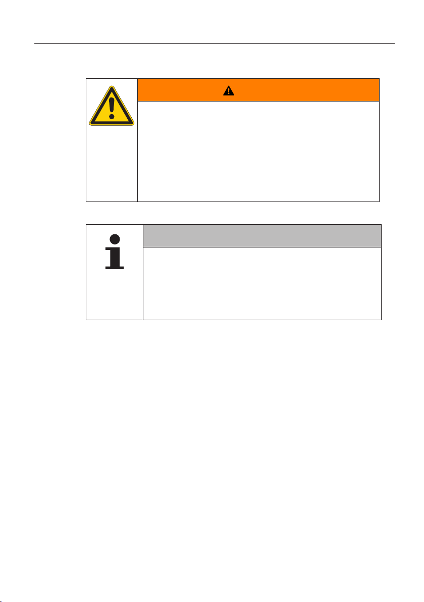
1.6 Warnings
In the current user manual, the following warnings are used:
WARNING
A warning of this hazard level indicates a hazardous
situation.
If the hazardous situation is not avoided, it can result in
serious injuries.
► Follow the instructions in this warning to avoid serious
injuries to persons.
ATTENTION
A warning of this category indicates potential danger to
property.
If the situation is not avoided, it may lead to damage to
property.
► Follow the instructions in this warning to avoid dam-
age to property.
NOTE
► A note contains additional information that is im-
portant for further processing or for simplifying the
procedure step explained.
9
1.7 Manufacturer's address
Continental Reifen Deutschland GmbH
Büttnerstraße 25
30165 Hannover
Germany
www.contipressurecheck.com
1.8 After-sales service
In the case of technical questions on the display, pressure control indicator or the entire ContiPressureCheckTM system, please contact your CPC
supplier or the authorized garage that installed the CPC system.
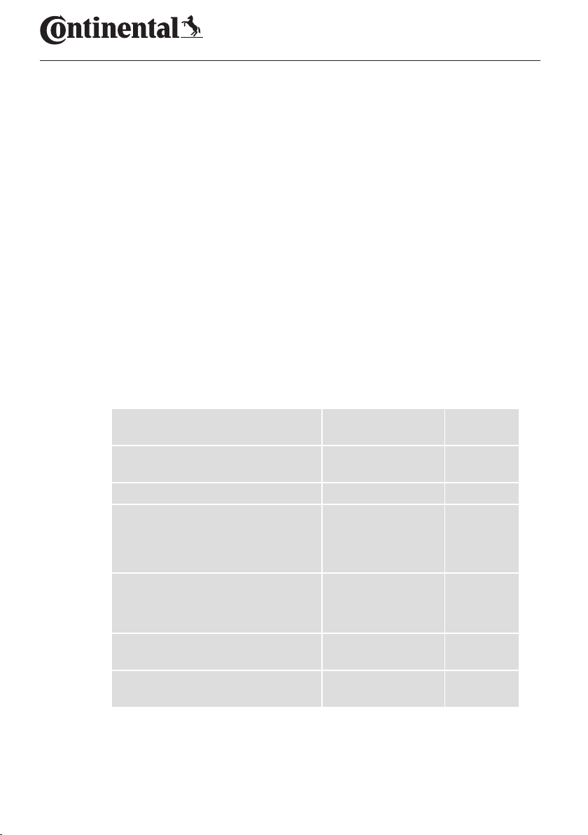
2 Technical data display
Technical data display
Dimensions (L x W x H)
Weight
Supply voltage 12/24 V
Number of plugging cycles, min.
Connecting plug diagnosis
Connection plug supply
Number of plugging cycles, min.
Connecting plate holder for the
display
Operating temperature
Readability of the LCD without
restrictions
117 x 107 x 40
4.60 x 4.21 x 1.57
240
8.47
100
10
5 cycles
-40 to 85
-40 to 185
-20 to 80
-4 to 176
mm
inch
cycles
cycles
g
oz
°C
°F
°C
°F
10
Safety
3 Safety
3.1 Intended use
The display is only intended for displaying the data detected by the CPC
system (air pressure and temperature of the tires) as well as warning
messages.
The pressure control indicator installed in the trailer is intended to be
used for displaying the status of the CPC system at the trailer using light
signals.
Use for any other purpose is not considered as intended use.
No claims of any kind will be accepted for damage resulting from use of
the appliance for other than its intended purpose.
In such cases, the risk must be borne solely by the user.
WARNING
Danger resulting from improper use!
Any use other than and/or going beyond the intended
use of the CPC system can lead to damage and serious
injuries.
► Use the system only for its intended purpose.
11

3.2 General safety instructions
Observe the following general safety instructions to ensure safe handling
of the CPC system:
■ The operator must ensure that tires in which tire sensors are
installed, are only operated in vehicles, in which monitoring is
ensured by the CPC system.
■ If continuous technical monitoring is not ensured, the operator
must make sure that the condition of the tire sensor is checked
regularly, at the latest after 20,000 km (12,425 miles).
■ In the case of continued use of the tires on other vehicles where
monitoring is not ensured, the tire sensors must irst be removed
from the tires.
■ The operator of the vehicle must ensure that the CPC system is
properly installed and put into operation. This includes setting the
nominal pressures recommended in the tire guide, correct assignment of the tire sensors to the wheel position, etc.
Observe the following general safety instructions to ensure safe handling
of the display:
■ Check the display for visible damage before using. Do not put a
damaged display into operation.
■ Never open the housing of the display.
■ The display is designed for a temperature range from -40 °C to
85 °C (-40 to 185 °F) however, temporary display errors may occur
at temperatures lower than -20 °C (-4 °F) or above 80 °C (176 °F).
■ Protect the display against moisture and penetration by liquids.
Safety
12

Safety
3.3 Particular hazards
Special characteristic in the case of vehicles for hazardous substances
(ADR):
■ If the CPC system is installed in a vehicle for hazardous materials
(ADR) and the CPC system remains switched on although the vehicle ignition is switched o, it is possible that sparks, other ignition
sources or similar could lead to a reaction with the hazardous
material in the event of a fault. This can result in accidents and
serious injuries.
– For this reason, it is absolutely necessary when parking vehicles
for hazardous substances to disconnect the CPC system fro the
power supply (normally via the battery main switch)
13
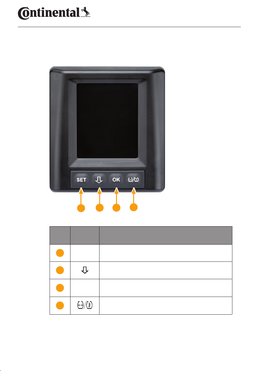
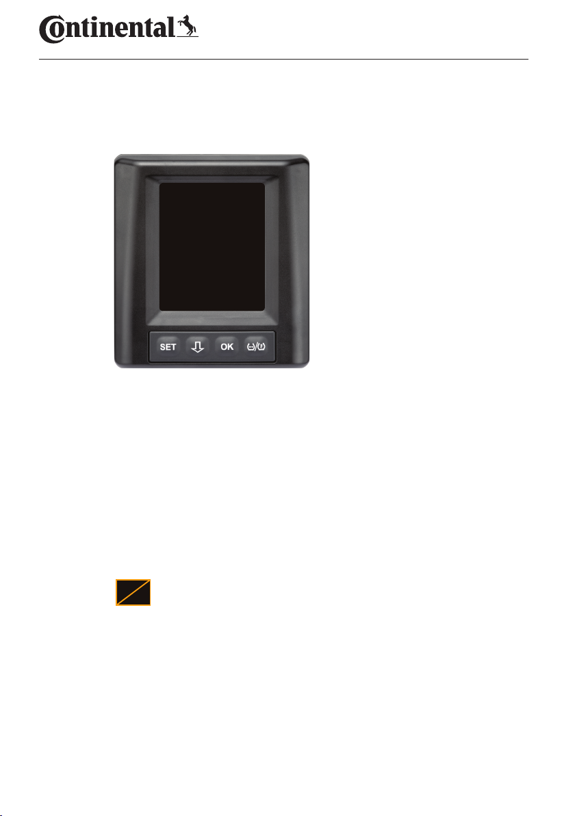
4 Tool overview
4.1 Operating keys
Tool overview
2 3
1
But-
ton
Symbol Task
1 SET Switch between vehicle view and setup
2
3 OK Conirmation of the selected menu item
4
Navigation between menu items and warning
messages
Switch between pressure or temperature display
in the vehicle view
4
14
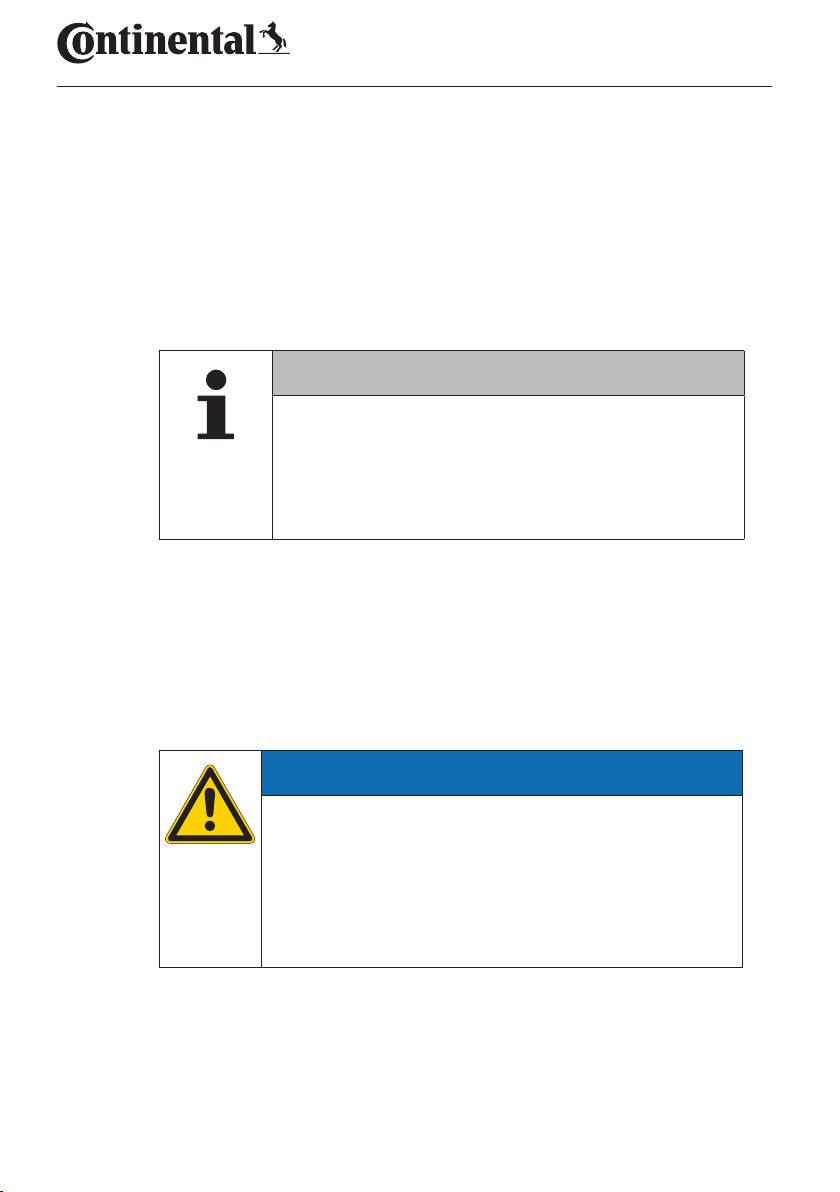
Mounting the display
5 Mounting the display
Risk of injury!
The risk of injury cannot be ruled out if the installation
instructions are not followed.
► Mount the display oset to the side of the driver and
the front passenger(s).
► Do not mount the display in the impact zone of the
body or the head and not in the airbag area (driver &
front passenger).
The vehicle driver must have a suicient ield of view
under all operating and weather conditions.
► Mount the display so that the ield of view of the
driver is not restricted.
WARNING
NOTE
15
Mounting the display
5.1 Display holder with suction caps for attaching to the
windscreen
To attach the display to the windscreen to the display holder, use the suction caps.
Connect the display with the display holder supplied. Make sure
that the display is completely snapped and locked into the holder.
Choose a suitable location on the windscreen. Pay attention to
possible dazzling by sunlight.
NOTE
National regulations!
► If national regulations stipulate that devices may no
be attached to the windscreen, mount the display
with the holder according to chapter “5.2 Display
holder for screwing to the dashboard”
5.2 Display holder for screwing to the dashboard
To mount the display to the dashboard, glue and screw the display holder
to the dashboard.
Connect the display with the display holder supplied.
Chose a suitable location on the dashboard. Pay attention to possi-
ble dazzling by sunlight.
ATTENTION
Damage!
In the case of improper screwing of the display holder, it
is possible to damage components or cables in the dashboard of the vehicle:
► Before screwing tight, maker sure that components
or cables cannot be damaged when ixing the display
holder.
16
Mounting the display
Remove the display from the holder.
Pull of the protective foil of the contact surfaces on the holder and
glue the holder to the desired location.
Also screw the holder into the dashboard with the 2 screws sup-
plied.
Connect the display with the display holder supplied. Make sure
that the display is completely snapped and locked into the holder.
It is recommended to ix the display by gluing and
screwing!
► The adhesive foil compensates unevenness between
the holder and installation location and ensures a
tighter it.
► The screws secures the holder against vibration during
operation and therefore against unintentional loosening.
Dismantling the display holder!
► After dismantling the display holder, two holes remain
in the dashboard. In addition, residual adhesive could
remain on the dashboard.
NOTE
NOTE
5.3 Adjusting the display
Adjust the display with the help of the holder.
► The display must always be clearly visible to the driver.
NOTE
17
6 Commissioning
!
6.1 Start screen
CONTINENTAL
6.2 Warnings
Commissioning
The start screen is displayed for
10 seconds after ignition.
After the start screen is displayed, the applicable warnings for proper use
of the system are displayed for 30 seconds at a time.
The warning message for deactivated warnings only appears if the warning messages on a special vehicle have been deactivated.
The setting can be selected during coniguration with the hand-held tool
and suppresses any warning messages except for the pressure loss warning message.
In addition to the warning, the corresponding icon for deactivated warnings is permanently displayed on the screen.
18

Commissioning
6.3 Automatic Language Query
► By default, the automatic language query is activated
for initial startup
■ If the automatic language query is activated, the display switches
from the start screen to setup - Language view, see chapter “6.3.1
Setting the language for automatic language query”.
If no button is pressed within 15 seconds, the display switches
automatically to the vehicle view.
■ If the automatic language query is deactivated, the display imme-
diately switches from the start screen to the vehicle view.
NOTE
19
Commissioning
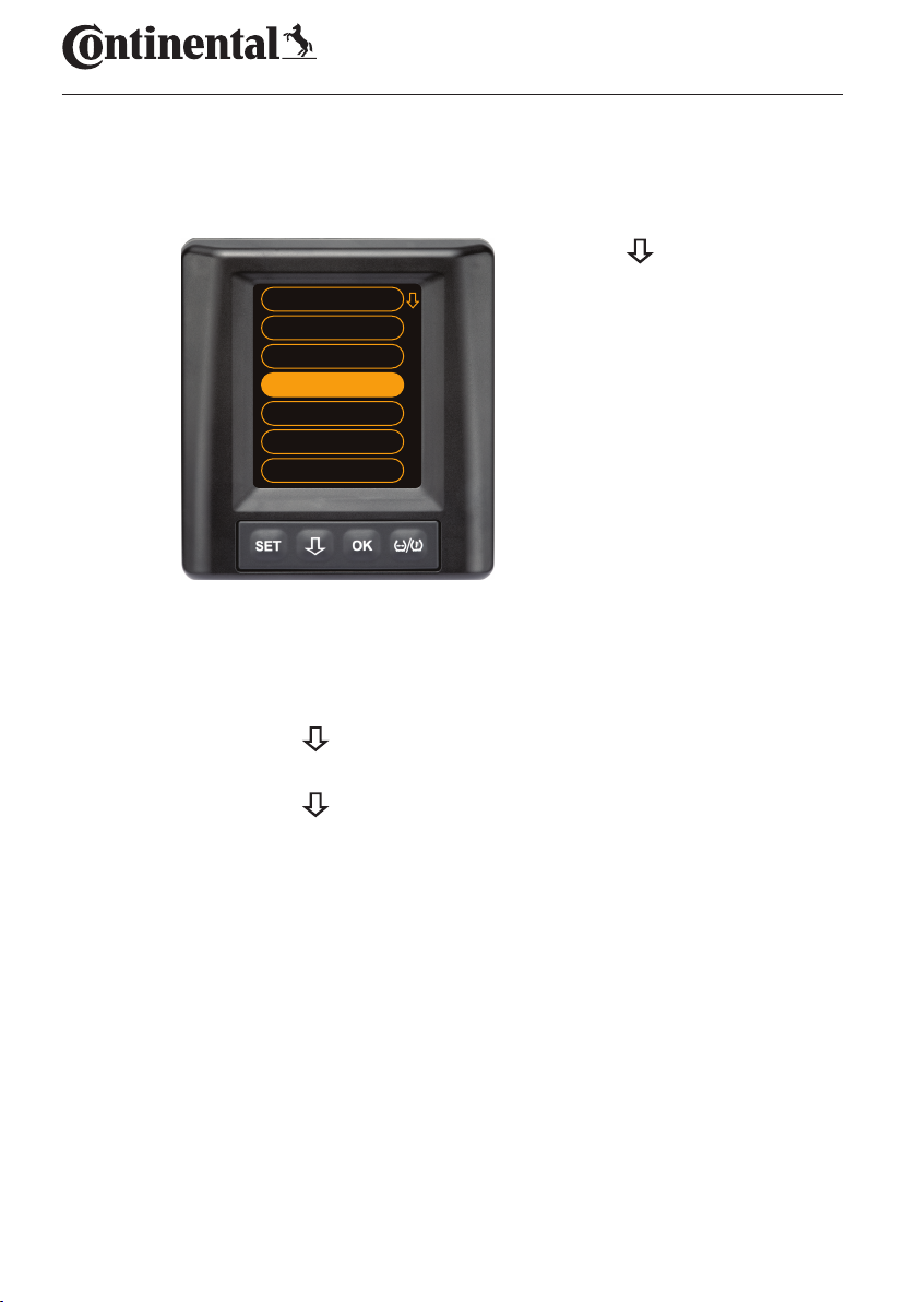
6.3.1 Setting the language for automatic language query
If the automatic language query is activated, the Settings - Language
view appears for 15 seconds.
Press the button to
Autostart ON
Česky
Deutsch
English
Español
Français
Italiano
6.3.2 Activate/deactivate automatic language query
select a language (the
selected language is
highlighted).
Press the OK button to
conirm the language
selection.
The display switches to
the vehicle view.
Press the SET button, the Setup view is displayed.
Press the
button to select the "Language" menu item.
Press the OK button to conirm.
Press the
button to select the "Autostart" menu item.
Select "Autostart ON“ or "Autostart OFF" with the OK button.
20
Operation
7 Operation
7.1 Safety precautions
Danger of accident!
Operating the display while driving can lead to accidents.
An incorrectly or carelessly mounted display can impair
driving safety!
■ The ContiPressureCheck
pressure. The responsibility for the correct pressure lies with the
driver.
■ Increase the tire pressure only when the tire temperature corre-
sponds to the ambient temperature.
■ The ContiPressureCheck
be completely ruled out in the event of adverse conditions that the
CPC system does not display any warnings or conversely, that the
CPC system displays an incorrect warning.
WARNING
► Do not operate the display while driving.
► View the screen only if the traic situation allows.
► Before each journey, check the seating of the display
and stability of the holder.
TM
system supports monitoring of tire
TM
system is a comfort system. It cannot
NOTE
► Use of snow chains can impair the transmission power
of the tire sensors in the corresponding tires. This can
lead to a delay in transmitting the tire pressures and
the resulting warning messages for those tires.
21
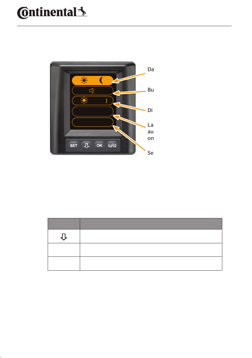
7.2 Setup menu
The following functions can be set in the settings menu:
→
(100%)
English
Operation
Day/night mode
Buzzer ON/OFF
Display brightness
bar / °C
7.2.1 Open the settings menu
Press the SET button to open the settings menu.
7.2.2 Navigating the settings menu
Button Task
Select between the menu items, selection is highlighted
OK Change settings or open submenus
SET Return to vehicle view
If no button is pressed within 30 seconds, the display switches automatically to the vehicle view
Language selection and
automatic language query
on/o
Selection of units
22
Operation
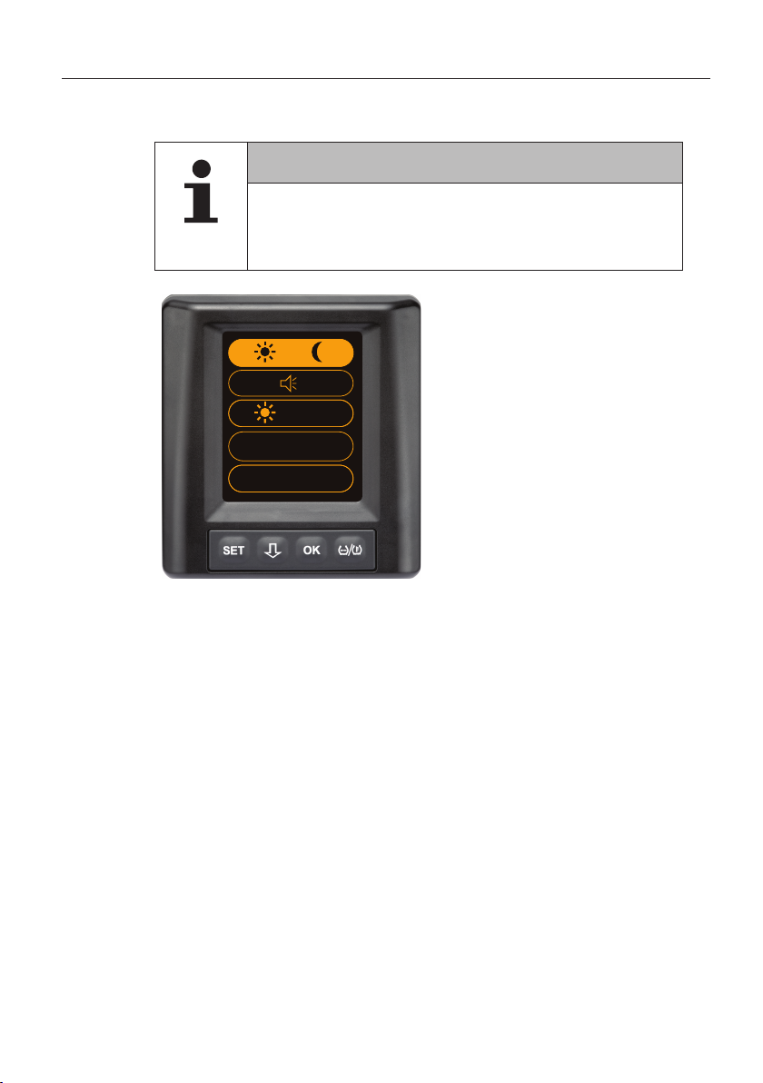
7.2.3 Day/night mode
NOTE
► The display brightness is adjusted to the day and
night conditions with the day/night mode. No dazzling
during night driving and suicient readability during
the day.
Press the OK button
to switch to the night
→
(100%)
English
bar / °C
mode or the vice versa.
Switching depends on the
last setting. The display
switches back to the
vehicle view.
23
 Loading...