

Continental Refrigerator C75, C85, C90, O-200 Overhaul Manual

C75
C85
C90
O-200
CONTINENTAL® AIRCRAFT ENGINE
OVERHAUL
MANUAL
FAA APPROVED
Publication X30010
©
2011 CONTINENTAL MOTORS, INC. AUG 2011

Supersedure Notice
This manual revision replaces the front cover and list of effective pages for Pub lication Part No. X30010, dated
January 1984. Previous editions are obsolete upon release of this manual.
Effective Changes for this Manual
0...............January 1984
1............31 August 2011
List of Effective Pages
Document Title: C75, C85, C90 & O-200 Series Engines Overhaul Manual
Publication Number: X30010 Initial Publication Date: January 1984
Page Change Page Change Page Change Page Change
Cover............................1
A...................................1
1 - blank added............1
2 thru 124.....................0
Published and printed in the U.S.A. by Continental Motors, Inc.
Available exclusively from the publisher: P.O. Box 90, Mobile, AL 36601
Copyright © 2011 Continental Motors, Inc. All rights reserved. This material may not be reprinted, republished, broadcast, or otherwise
altered without the publisher's written permission. This manual is provided without express, statutory, or implied warranties. The publisher will
not be held liable for any damages caused by or alleged to be caused by use, misuse, abuse, or misinterpretation of the contents. Content is
subject to change without notice. Other products and companies mentioned herein may be trademarks of the respective owners.
A C75, C85, C90 & O-200 Series Engines Overhaul Manual
31 August 2011

INTENTIONALLY
LEFT
BLANK
2
FOREWORD
This manual
is
published for the guidance
of
all facilities engaged in
operation, maintenance and overhaul
of
four cylinder engines
of
the
Teledyne Continental C
and
0-200
Series.
A description
is
included in this manual
of
the various models
and
special
equipments
of
the
series
and
photographs selected
to
illustrate
the
major
differences between models. The Table
of
Specifications provides more
detailed information in regard
to
features
and
performance
of
the
models.
It
should be noticed
that
such descriptive material
is
neither intended
nor
adequate
to
enable conversion
of
any model
to
another
in instances in which
such conversion
is
permissible.
For
detailed information regarding
application
of
parts
and
their interchangeability, refer
to
the
Spare Parts
Catalog.
For
model
and
series number conversion instructions, refer
to
the
Teledyne Continental Service Bulletin
on
that
subject.
Service maintenance instructions relative
to
accessories installed
on
Teledyne
Continental aircraft engines in
our
factory are reprinted herein
by
permission
of
the
accessory manufacturers. Instructions for overhaul
of
these acces-
sories may be obtained direct from
the
manufacturers
or
through their
authorized service facilities.
All descriptive
and
dimensional information
and
all instructions contained in
this edition have been revised and extended
to
cover all four cylinder models
of
the Teledyne Continental C Series in current production. The parts
catalog section
is
not
included in this edition, since
it
is subject
to
frequeht
change in details.
A manual
of
this scope cannot be revised
often
enough
to
be kept up
to
date
at all times, since
it
is
our
policy
to
improve details
of
engine design
in
the
interest
of
maximum safety and utility
of
our
products whenever the results
of
our
continuous experimental and development program indicate the
desirability
of
replacing the old
with
something even better.
For
this reason
we issue Service Bulletins
to
our
Approved Distributors
to
advise
of
important changes in parts, desirable inspections
and
precautions found
necessary in operation and maintenance. These bulletins are available for
reading
at
all Teledyne Continental Approved Service Stations. Those who
need permanent copies
of
Service Bulletins may obtain
them
by
direct mail,
as
issued, from the factory Publications Department
on
an
annual
subscription basis. A nominal charge
is
made
to
cover
the
cost
of
mailing.
It
is
suggested
that
a careful study
of
the
text
of
this manual will provide the
reader with knowledge
of
engine constrq.ction
and
of
techniques for
both
operation
and
repair work which,
if
applied in practice, will
promote
safety
in flight
and
long engine life.
If,
in
spite
of
the
high quality
of
materials
and
the careful inspection
and
testing
of
these engines, any defect
is
suspected,
the
question should be
brought immediately
to
the
attention
of
the nearest Teledyne Continental
Approved Service Station so
that
a diagnosis
and
any necessary correction
may be made.
Section
&
Para.
1-1
1-2
1-3
1-4
II
III
3-1
3-2
3-3
3-4
3-5
3-6
3-7
3-8
3-9
3-10
3-11
3-12
3-13
3-17
3-18
3-19
3-25
3-26
3-27
3-28
3-29
3-30
3-36
3-37
3-38
3-39
3-40
3-41
IV
4-1
4-2
4-3
4-4
V
5-1
5-2
5-3
TABLE
OF
CONTENTS
Tide
Page
Introduction.
. . . . . . . . . . . . . . . . . . . 9
Model Designation. . . . . . . . . . . . . . . . 9
Definitions
and
Abbreviations.
. . . . . . . 9
Measurement.
. . . . . . . . . . . . . . .
... . 10
Cleanliness. . . . . . . . . . . . . . . . . . . . .
10
Table
of
Specifications.
. . . . . . . . . . . . 11
General
Description.
. . . . . . . . . . . . . . 16
Difference Between Model
Groups.·.
. . . 16
Significance
of
C Series Dash
Numbers
and
Letters
. . . . . . . . . .
..
16
Model Conversions. . . . . . . . . . . . . . . .
16
Optional
Equipment
. . . . . . . . . . . . . . 17
Superseding
Parts
. . . . . . . . . . . . . . . .
17
Crankcase
Construction
. . . . . . . . . . . . 17
Crankshafts . . . . . . . . . . . . . . . . . . . . 18
Nitrided
Crankshafts.
. . . . . . . . . . .
..
18
Crankshaft
Gears. . . . . . . . . . . . . . . . . 19
Connecting
Rods.
. . . . . . . . . . . . . . . . 19
Camshafts.
. . . . . . . . . . . . . . . . . . . . 19
Camshaft
Gears. . . . . . . . . . . . . . . . . . 19
Hydraulic Valve Lifters. . . . . . . . . . . . .
20
Push rods
and
Housings.
. . . . . . . . . .
..
21
Piston
Assemblies.
. . . . . . . . . . . . . . . 21
Cylinder
Assemblies. . . . . . . . . . . . .
..
21
Crankcase Cover Assembly
for
-12, -14, -16 &
0-200
Models.
. . . .
..
22
Crankcase Cover Assembly
for
-8 Models. . . . . . . . . . . . . . . . . . . . 23
Gear
Train.
. . . . . . . . . . . . . . . . . . . . 23
Carburetor
Induction
System. . . . . . . . . 24
Oil
Sumps
. . . . . . . . . . . . . . . . . . .
..
24
Ignition System. . . . . . . . . . . . . . . . . . 24
Deko-Remy
Starter.
. . . . . . . . . . . . . . 25
Prestolite
Starter.
. . . . . . . . . . . . . . . . 26
Generator
and
Drive. . . . . . . . . . . . .
..
26
Side
Mounted
Fuel
Pump.
. . . . . . . . . . 26
Duel
Fuel
Pump
Equipment
. . . . . . .
..
26
Lubrication
System.
. . . . . . . . . . . . . . 27
Unpacking
the
Engine . . . . . . . . . . . . . 29
Shipping
Crates. . . . . . . . . . . . . . . . . . 29
Method
of
Packing
and
Preservation . . . . 29
Removal
of
Engine
from
Crate.
. . . . . . .
30
Preparation
for
Installation.
. . . . . . . . .
30
Storage
of
Engines. . . . . . . . . . . . . . . . 31
General
..............................
31
Flyable Storage
.......................
31
Temporary
Storage
....................
31
Section
& Para.
5-4
5-5
5-6
VI
6-1
6-2
6-3
6-4
6-5
VII
7-1
7-2
7-3
7-4
7-5
7-6
7-7
7-8
7-9
7-10
7-11
7-12
7-13
7-14
VIII
IX
9-1
9-2
9-3
X
10-1
10-7
10-18
10-24
10-30
10-38
10-47
XI
11-1
11-10
Tide
Page
Indefinite Storage
.....................
32
Procedure
For
Return
of
AIC
to
Service 33
Indefinite Storage Inspection
............
33
Installation
in Airplane &
Removal.
. . . .
34
Mounting
the
Engine.
. . . . . . . . . . . . .
34
Fuel
Systems . . . . . . . . . . . . . . . . . . .
38
Oil
System.
. . . . . . . . . . . . . . . . . .
..
38
Propeller
Installation.
. . . . . . . . . . . . . 38
Engine Removal . . . . . . . . . . . . . . .
..
39
Operating
Instruction.
. . . . . . . . . . .
..
40
Procedure
Preliminary
to
Starting.
. . .
..
40
Starting
Procedure.
. . . . . . . . . . . . . . .
40
Warm-Up.
. . . . . . . . . . . . . . . . . . .
..
40
Ground
Test.
. . . . . . . . . . . . . . . . .
..
40
Take-Off.
. . . . . . . . . . . . . . . . . . .
..
41
Climbing.
. . . . . . . . . . . . . . . . . . .
..
41
Level
Flight.
. . . . . . . . . . . . . . . . .
..
41
Let-Down
and
Landing. . . . . . . . . . .
..
42
Stopping
the
Engine. . . . . . . . . . . . .
..
42
Lubricating
Oil
......
'.'
. . . . . . . .
..
42
Viscosity
.............................
42
Oil Change Periods
....................
42
Oil Change
Procedure
.................
43
Engine Fuel
..........................
43
Engine
Troubles
and
S.ervice
Repairs
...........
, . . . . . . .
..
44
Periodic
Inspection
and
Maintenance. .
..
48
Daily
Inspection.
. . . . . . . . . . . . . .
..
48
First
Fifty
Hour
Inspection
.........
, 48
100-Hour
Periodic
Inspection
. . . . . .
..
49
Adjustment
and
Minor
Repair.
. . . . . . .
51
Carburetors.
. . . . . . . . . . . . . . . . . . .
51
Magnetos.
. . . . . . . . . . . . . . . . . . . . .
53
Replacement
of
Ignition
Cables.
. . . . . .
57
Delco-Remy
Starter.
. . . . . . . . . . . .
..
59
Prestolite
Starter.
. . . . . . . . . . . . . .
..
60
Generator
and
Drive. . . . . . . . . . . . . . . 62
Hydraulic Valve Lifters. . . . . . . . . . . . .
64
Disassembly.
. . . . . . . . . . . . . . . . . . . 67
Preliminary
Operations.
. . . . . . . . . . . . 67
Disassembly.
. . . . . . . . . . . . . . . . . . . 68
3
TABLE
OF
CONTENTS
(Con't)
Section
Section
& Para. Title Page
& Para.
Title Page
XII
Cleaning
............................................
72
XVI
Final Assembly. . . . . . . . . . . . . . . . . .
97
12-1
Materials and Processes
.............
72
16-1 General
Procedure.
. . . . . . . . . . . . . . .
97
12-6
Specific Parts
...................
72
16-4 Detailed Procedure . . . . . . . . . . . . . . .
97
XIII
Inspection
.....................
74
XVII Testing
after
Overhaul . . . . . . . . . . . .
106
13-1
Definitions
.....................
74
17-1
Testing Equipment
....................
106
13-2
Inspection Tools
.................
74
17-2
Test Stand
...........................
106
13-5
Inspection Methods
...............
75
17-3
Instruments.
. . . . . . . .
.. . .. . ..
. . . . . . . . . .
106
13-14
Inspection
of
Critical Parts
..........
77
17-4
Test Club
............................
106
17-5
Test After Overhaul
...................
106
XIV
Repair and Replacement. . . . . . .
.....
81
17-6
Preservation
..........................
111
14-1
General Repair
..................
81
17-7
Fuel
and
Lubricating Oil
...............
111
14-7
Repair
and
Replacement
of
17-8
Testing Engines Installed in Aircraft
.....
111
Specific Parts
.................
82
17-9
Inspection
............................
111
14-13A
Crankcase Modification
........................
87
XVIII Table
of
Limits.
. . . . . . . . . . . . . . . .
114
14-21
Protective Coatings . . . . . . . .
.......
90
XV Assembly
of
Subassemblies
..........
93
15-1 General Procedure
................
93
15-4 Detailed Procedure
..............................
93
•
LIST
OF
TABLES
Table
Table
No.
Title
Page
No.
Title
Page
Features Common
to
all
Models
.......
11 XIV
Accessory Drive Speed Ratios
II
Type
Certificate Numbers
11 and
Rotation
.................
14
III
Features Peculiar
to
Each
XV
Line and
Instrument
Connections
......
14
Model Group
..................
11
XVI
Weights
of
Standard Engine
IV
Dimensions Peculiar
to
Each Model
Equipment
...................
15
or
Model Dash
Number
..........
11
XVII
Additional Weights
of
Optional
V
Speed and Power Ratings
...........
12
Equipment
...................
15
VI
Operating Temperature Limits
........
12
XVIII
Recommended
Oil Viscosity Grades
....
43
VII
Operating Pressure Limits
............
12
XIX
Magnflux Inspection Data
.. , ........
77
VIII
Model
or
Model Dash Number
XX
Stud
Identification Chart
...........
81
Equipment
...................
12
XXI
Test
Operating Limits
.............
109
IX
General Ignition System
XXII
Test Schedule
..................
110
Specifications
.................
13
XXIII
Oil Sump Capacity
...............
III
X
Ignition Timing
..................
13
XXIV
General Use - Tightening Torques
.....
118
XI
Valve Mechanism Specifications
.......
13
XXV
Pipe Plugs
........................................
118
XII
Lubrication System Specifications
.....
13
XIII Fuel Metering System
Specifications
.................
14
4
Figure
No.
1.
2.
3.
4.
5.
6.
7.
8.
9.
10.
II.
12.
13.
14.
15.
16.
17.
18.
19.
20.
21.
22.
23.
24.
25.
26.
27.
28.
29.
30.
31.
32.
33.
34.
35.
36.
37.
38.
39.
40.
41.
42.
43.
44.
45.
39.
40.
LIST
OF
ILLUSTRATIONS
Page
Left
Side View, Model
C85-12F.
. . . . . . . . . . . . . . . . . . . . . . . . . . . . . . . . . . . . . . . . . . . .
..
6
Three-Quarter
Right
Rear
View, Model
C85-12.
. . . . . . . . . . . . . . . . . . . . . . . . . . . . . . . . . .
..
6
Three-Quarter
Left
Front
View, Model C90-16F . . . . . . . . . . . . . . . . . . . . . . . . . . . . . . . . . .
..
7
Three-Quarter
Right
Rear View, Model C90-16F . . . . . . . . . . . . . . . . . . . . . . . . . . . . . . . . . .
..
7
Right
Front
View, Model C-90. . . . . . . . . . . . . . . . . . . . . . . . . . . . . . . . . . . . . . . . . . . . . .
..
8
Left
Front
View, Model
0-200.
. . . . . . . . . . . . . . . . . . . . . . . . . . . . . . . . . . . . . . . . . . . . .
..
8
Cylinder Arrangement Diagram (Top View)
.......................................
10
Section Through Hydraulic Valve Lifter
..........................................
20
Crankcase Cover and Accessories
of
-12, -14, -16 and
0-200
Models
.......................
22
Gear Train
of
-12, -14, -16
and
0-200
Models
......................................
24
Hoisting Engine
by
Crankshaft Lifting Eye
........................................
29
Typical Installation Diagram
for
-12, -14 & -16 Models, Side View
........................
35
Installation Drawing
for
-12,
-14
& -16 Models,
Front
View
.............................
35
Installation Drawing
for
-12,
-14
& -16 Models, Rear View
.............................
36
Installation Drawing
for
-12,
-14
& -16 Models, Side and Top Views
.......................
37
Engine Mounting
Equipment
of
Models C90-14 & 16 and
0-200
.........................
38
Ignition Wiring
Diagram.
. . . . . . . . . . . . . . . . . . . . . . . . . . . . . . . . . . . . . . . . . . . . . . . . . . .
57
Removal
of
Hydraulic
Unit
from Valve Lifter Body
..................................
69
Compressing Valve Spring
to
Remove Locks
.......................................
71
Removing Plunger from Hydraulic
Unit
with
Taped
Pliers
..............................
71
Installing Helical Coil
Inserts.
. . . . . . . . . . . . . . . . . . . . . . . . . . . . . . . . . . . . . . . . . . . . . . . .
82
Dimensions
of
Rocker
Shaft
Boss Bushings. . . . . . . . . . . . . . . . . . . . . . . . . . . . . . .
..
. . . . .
..
84
Drill
Fixture.
. . . . . . . . . . . . . . . . . . . . . . . . . . . . . . . . . . . . . . . . . . . . . . . . . . . . . . . . . . .
87
Drilling Hole in Bearing . . . . . . . . . . . . . . . . . . . . . . . . . . . . . . . . . . . . . . . . . . . . . . . . . .
..
88
Drilling
Adapter
Assembly . . . . . . . . . . . . . . . . . . . . . . . . . . . . . . . . . . . . . . . . . . . . . . . .
..
88
Plug
Detail.
. . . . . . . . . . . . . . . . . . . . . . . . . . . . . . . . . . . . . . . . . . . . . . . . . . . . . . . . . .
..
89
Drill
Fixture.
. . . . . . . . . . . . . . . . . . . . . . . . . . . . . . . . . . . . . . . . . . . . . . . . . . . . . . . . .
..
89
Drill
Fixture
Installed. . . . . . . . . . . . . . . . . . . . . . . . . . . . . . . . . . . . . . . . . . . . . . . . . . . .
..
89
Name Plate Change
.......................................................
89
Tightening
No.1
Connecting
Rod
Bolts
..........................................
95
Installing Crankshaft Bearing and Old
Type
Thrust
Washer.
. . . . . . . . . . . . . . . . . . . . . . . . . .
..
97
Installing Crankshaft and Connecting Rods. . . . . . . . . . . . . . . . . . . . . . . . . . . . . . . . . . . . . . . .
98
Installing Dowel
Type
Thrust
Washers and Split Oil
Seal.
. . . . . . . . . . . . . . . . . . . . . . . . . . . . . .
98
Installing
Starter
Pinion Pivot . . . . . . . . . . . . . . . . . . . . . . . . . . . . . . . . . . . . . . . . . . . . . .
..
99
Installing Crankcase 1, 3 Side on
2,4
Side.
. . . . . . . . . . . . . . . . . . . . . . . . . . . . . . . . . . . . .
..
99
Installing Crankcase Cover
on
-12, -14, -16 and
0-200
Models
.........
'
..................
102
Installing No. 3 Cylinder
....................................................
103
Installing
"0"
Rings
on
Intake Manifold Studs
..............•......................
103
placing Crankshaft in Firing Position
of
No.1
Piston
.................................
104
Placing Flange Crankshaft in Firing Position
of
No.1
Piston
............................
104
Fuel Flow Limits
vs.
RP.M.
at
Propeller Load, Model C90
.............................
112
Fuel Flow Limits vs. R.P.M.
at
Propeller Load, Models C75
and
C85
.......................
112
Fuel
Flow
Limits vs.
RP.M.
at
Propeller Load, Model
0-200
............................
113
Limits and Lubrication
Chart
(Sheet 1
of
4)
- Cross Section View
.........................
120
Limits and Lubrication
Chart
(Sheet 2
of
4)
- Longitudinal Section View
....................
121
Limits and Lubrication
Chart
(Sheet 3
of
4)
- Rear View & Horizontal Section - 8 Models
.........
122
Limits and Lubrication
Chart
(Sheet 4
of
4)
- Rear View & Sections,
-12, -14 and
0-200
Models
.................................................
123

Figure
1.
Left Side View, Model C85-12F.
Figure
2.
Three-Quarter Right Rear View, Model C85-12.
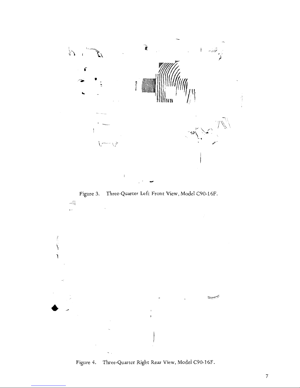
Figure 3. Three-Quarter Left
Front
View, Model C90-16F.
Figure 4. Three-Quarter Right Rear View, Model C90-16F.
7
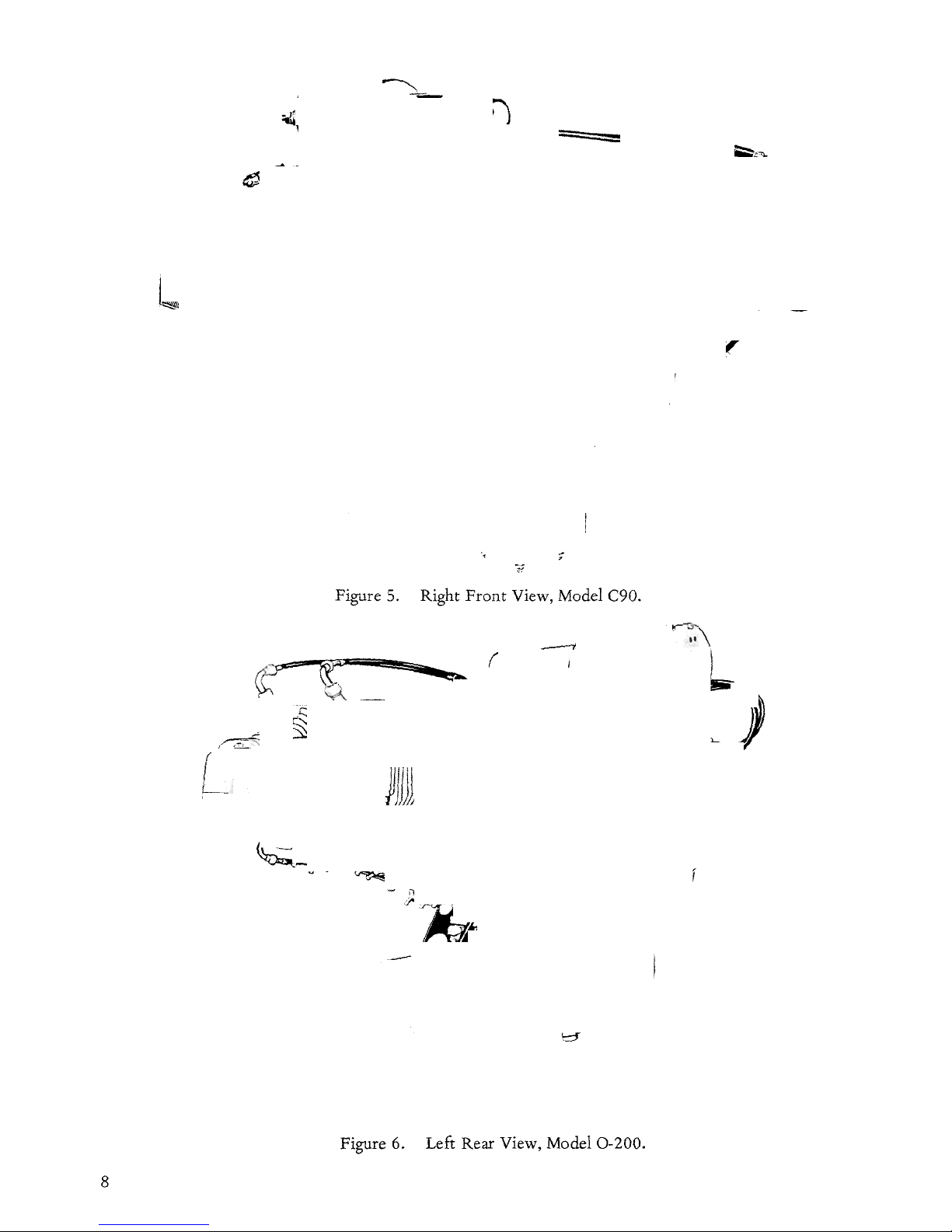
Figure 5. Right
Front
View, Model C90.
Figure 6. Left Rear View, Model
0-200.
8

SECTION I
INTRODUCTION
1.1 MODEL DESIGNATIONS.
This publication covers
the
maintenance
and
overhaul instructions applicable
to
the
four
cylinder C Series
and
the
0-200
Aircraft Engines. C
Series Engines covered
by
this publication fall
into
three model groups, namely, C75,C85
and
C90,
according
to
normal
rated
horsepower. Within each
C model group, variations in
equipment
of
the
basic engine are
denoted
by
suffix dash numbers,
as
explained in
the
Table
of
Specifications.
Further
explanation
of
the
meaning
of
model
dash
numbers
applicable
to
C models will be
found
in Section III.
Each engine bears an identification plate,
on
which
is
stamped
the
information
peculiar
to
that
particular model, including
the
exact
model
and
dash
number
designation
and
the
engine serial
number.
NOTE
If a new
nameplate
is required,
refer
to
Service Bulletin M7S-S.
All
correspondence
with
Teledyne
Continental
Distributors
and
with
the
factory
Service De-
partment
in
regard
to
specific engines
should
refer
to
the
exact
model
designation
and
serial
number.
1-2. DEFINITIONS & ABBREVIATIONS
A.B.e.
Approx.
A.T.e.
Bar.
B.B.C.
B.
H.
P.
B.
T.
e.
F.
A. A.
After
Bottom
Center
Approximately
After
Top
Center
Barometric
Before
Bottom
Center
Brake Horsepower
Before
Top
Center
Federal Aviation
Administration
e.
F.
M.
e.G.
Dia.
o
o
F.
Fig.
Front
Ft.
G.P.M.
H20
Hg.
I.D.
In. (")
Hex.
Hr.
Left
Side
Lbs.
Lockwire
Man.
Max.
Min.
30'
N.P.T.
N.C.
N.F.
O.D.
Press.
P.
S.1.
Rear
Right Side
R.P.M.
Std.
T.D.e.
Temp.
Torque
Cubic
Feet
Per Minute
Center
of
Gravity
Diameter
Degree
of
Angle
Degrees
Fahrenheit
Figure (Illustration)
Propeller
End
Foot
or
Feet
Gallons Per Minute
Water
Mercury
Inside
Diameter
Inches
Hexagon
Hour
Side
on
Which
No's
2 & 4 Cylinders
Located
Pounds
Soft Steel Wire Used
to
Safety
Connections, Etc.
Manifold
or
Manometer
Maximum
Minimum
Thirty
Minutes
of
Angle
(60'
Equals One
0)
National Pipe
Thread
(Tapered)
National Coarse (Thread)
National Fine (Thread)
Outside Diameter
Pressure
Pounds
Per
Square
Inch
Accessory
End
of
Engine
Side
on
Which
No's
1 & 3 Cylinders
Located
Revolution Per Minute
Standard
Top
Dead
Center
Temperature
Force
X Lever
Arm
(125 ft. lbs.
torque
= 1251bs.
Force
Applied
One
Ft.
From
Bolt
Center
or
62-1/2
lbs. Applied 2
Ft.
From
Center)
9
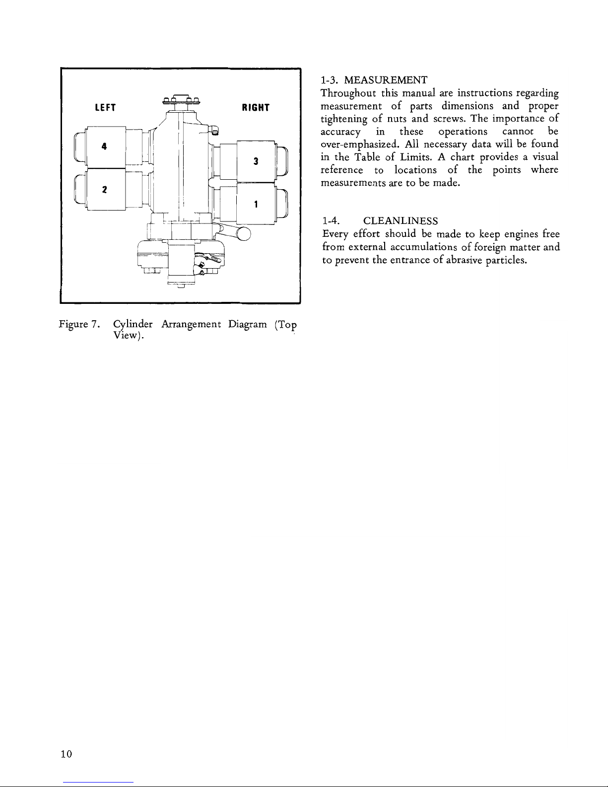
LEFT
RIGHT
4
3
2
1
Figure 7. Cylinder Arrangement Diagram (Top
View).
10
1-3. MEASUREMENT
Throughout
this manual are instructions regarding
measurement
of
parts dimensions
and
proper
tightening
of
nuts
and
screws. The importance
of
accuracy in these operations
cannot
be
over-emphasized. All necessary
data
will be found
in
the
Table
of
Limits. A chart provides a visual
reference
to
locations
of
the
points where
measurements are
to
be made.
1-4. CLEANLINESS
Every effort should be made
to
keep engines free
from external accumulations
of
foreign
matter
and
to
prevent
the
entrance
of
abrasive particles.
SECTION
II
TABLE
OF
SPECIFICATIONS
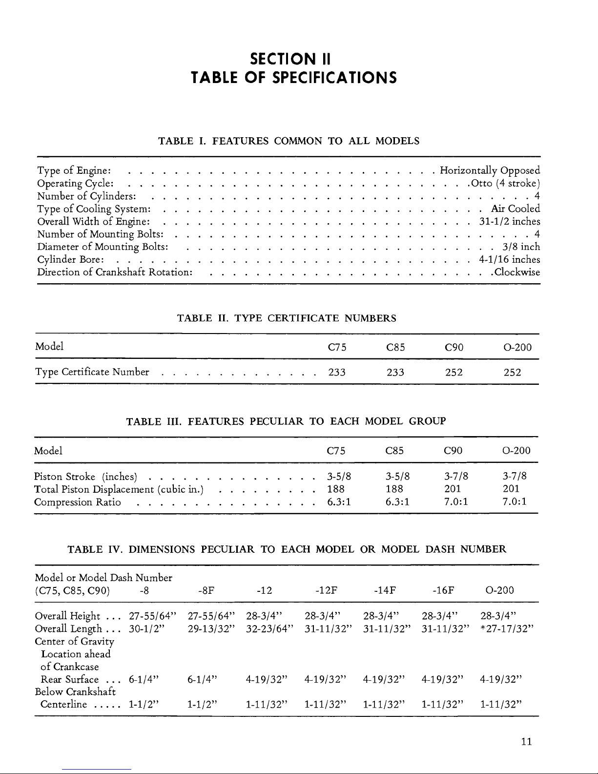
TABLE
I.
FEATURES
COMMON
TO
ALL
MODELS
Type
of
Engine:
Operating Cycle:
Number
of
Cylinders:
Type
of
Cooling System:
Overall Width
of
Engine:
Number
of
Mounting Bolts:
Diameter
of
Mounting Bolts:
Cylinder Bore: . . . . .
Direction
of
Crankshaft Rotation:
TABLE II.
TYPE
CERTIFICATE NUMBERS
Model
C75 C85
Type Certificate Number
233 233
. Horizontally Opposed
C90
252
.
Otto
(4 stroke)
·
....
4
·
Air
Cooled
31-1/2 inches
·
....
4
· .
3/8
inch
4-1/16 inches
· .Clockwise
0-200
252
TABLE III. FEATURES PECULIAR
TO
EACH
MODEL
GROUP
Model C75
C85 C90
0-200
Piston Stroke (inches) . . . .
3-5/8 3-5/8
3-7/8 3-7/8
Total Piston Displacement (cubic
in.)
188 188
201
201
Compression Ratio
.
6.3:1 6.3:1
7.0:1 7.0:1
TABLE IV. DIMENSIONS PECULIAR
TO
EACH
MODEL
OR
MODEL
DASH NUMBER
Model or Model Dash Number
(C75, C85, C90)
-8 -8F -12
-12F
-14F
-16F
0-200
Overall Height
...
27-55/64" 27-55/64"
28-3/4" 28-3/4" 28-3/4" 28-3/4" 28-3/4"
Overall Length
...
30-1/2" 29-13/32" 32-23/64"
31-11/32"
31-11/32"
31-11/32"
*27
-17/32"
Center
of
Gravity
Location ahead
of
Crankcase
Rear Surface
...
6-1/4"
6-1/4"
4-19/32" 4-19/32"
4-19/32"
4-19/32"
4-19/32"
Below Crankshaft
Centerline
.....
1-1/2"
1-1/2" 1-11/32"
1-11/32"
1-11/32"
1-11/32" 1-11/32"
11
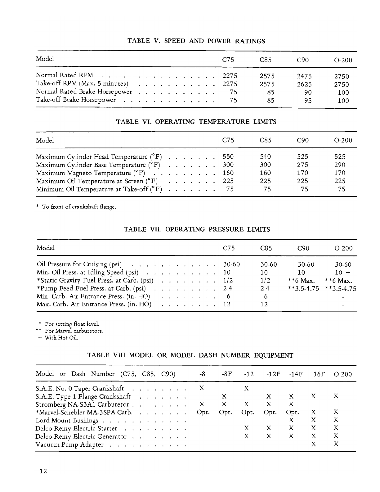
TABLE V. SPEED AND POWER RATINGS
Model
C75
C85
Normal
Rated
RPM
.
2275
2575
Take-off RPM (Max. 5 minutes)
2275
2575
Normal
Rated
Brake Horsepower
75
85
Take-off Brake Horsepower
75
85
TABLE VI. OPERATING TEMPERATURE LIMITS
Model
C75
C85
Maximum Cylinder Head Temperature (oF) 550 540
Maximum Cylinder Base Temperature
(OF)
300 300
Maximum Magneto Temperature
(0
F) 160 160
Maximum
Oil Temperature
at
Screen
(0
F)
225 225
Minimum Oil Temperature
at
Take-off
(0
F)
75 75
*
To front
of
crankshaft flange.
TABLE VII. OPERATING PRESSURE LIMITS
Model
Oil Pressure for Cruising (psi)
....
Min. Oil Press. at Idling Speed (psi)
*Static Gravity Fuel Press.
at
Carbo
(psi)
*Pump Feed Fuel Press.
at
Carbo
(psi)
Min.
Carbo
Air Entrance Press. (in. HO)
Max.
Carbo
Air
Entrance Press. (in. HO)
*
For
setting float level.
**
For
Marvel carburetors.
+ With
Hot
Oil.
C75
30-60
10
1/2
2-4
6
12
C85
30-60
10
1/2
2-4
6
12
C90
2475
2625
90
95
C90
525
275
170
225
75
C90
30-60
10
**6 Max.
**3.5-4.75
TABLE VIII MODEL
OR
MODEL DASH NUMBER EQUIPMENT
Model
or Dash Number
(C75,
C85, C90)
-8
-8F -12
-12F
-14F -16F
S.A.E. No. 0 Taper Crankshaft
X X
S.A.E. Type 1 Flange Crankshaft
X
X
X
X
Stromberg NA-S3A1 Carburetor .
X X X
X
X
*Marvel-Schebler MA-3SPA
Carbo
Opt. Opt. Opt. Opt. Opt.
X
Lord Mount Bushings . . .
X
X
Delco-Remy Electric Starter
.
X X X X
Delco-Remy Electric Generator
X X X X
Vacuum Pump Adapter .
X
12
0-200
2750
2750
100
100
0-200
525
290
170
225
75
0-200
30-60
10
+
**6 Max.
**3.5-4.75
0-200
X
X
X
X
X
X
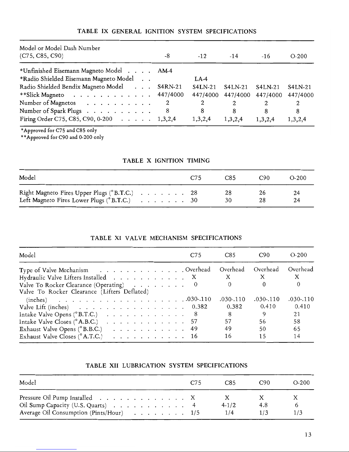
TABLE IX GENERAL IGNITION SYSTEM SPECIFICATIONS
Model
or
Model Dash Number
(C75, C85, C90)
-8
-12
*Unfmished Eisemann Magneto Model
AM-4
*Radio Shielded Eisemann Magneto Model LA-4
Radio Shielded Bendix Magneto Model
S4RN-21 S4LN-21
**Slick Magneto
447/4000
447/4000
Number
of
Magnetos
.
2
2
Number
of
Spark Plugs 8 8
Firing Order C75, C85, C90, 0-200 1,3,2,4 1,3,2,4
*Approved for
C7S
and
C8S
only
**Approved for C90 and 0-200 only
TABLE X IGNITION TIMING
Model
Right Magneto Fires Upper Plugs (OB.T.C.)
Left Magneto Fires Lower Plugs (OB.T.e.)
C75
28
30
-14
S4LN-21
447/4000
2
8
1,3,2,4
C85
28
30
TABLE XI VALVE MECHANISM SPECIFICATIONS
Model
C75
C85
Type
of
Valve Mechanism
. Overhead
Overhead
Hydraulic Valve Lifters Installed
X X
Valve To Rocker Clearance (Operating)
...
0 0
Valve To Rocker Clearance (Lifters Deflated)
(inches)
..
030-.110 .030-.110
Valve Lift (inches)
0.382
0.382
Intake Valve Opens (OB.T.e.)
8
8
Intake Valve Closes
(0
A.B.e.) 57
57
Exhaust Valve Opens (OB.B.e.)
49 49
Exhaust Valve Closes C A.T.e.)
16 16
TABLE XII LUBRICATION SYSTEM SPECIFICATIONS
Model
Pressure Oil Pump Installed . . . .
Oil Sump Capacity (U.S. Quarts)
Average Oil Consumption (Pints/Hour)
C75
X
4
1/5
C85
X
4-1/2
1/4
-16
S4LN-21
447/4000
2
8
1,3,2,4
C90
26
28
C90
Overhead
X
0
.030-.110
0.410
9
56
50
15
C90
X
4.8
1/3
0-200
S4LN-21
447/4000
2
8
1,3,2,4
0-200
24
24
0-200
Overhead
X
0
.030-.110
0.410
21
58
65
14
0-200
X
6
1/3
13
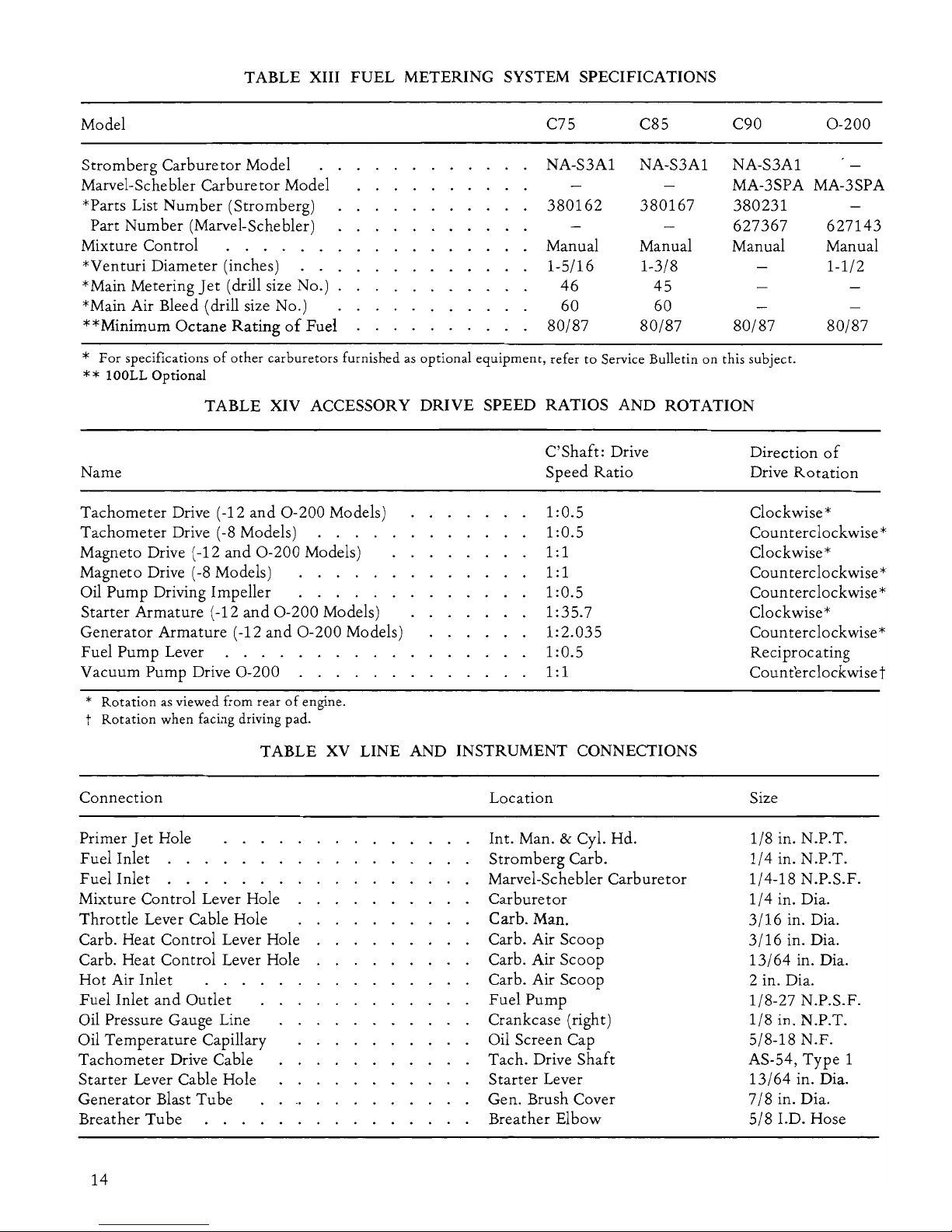
TABLE XIII FUEL METERING SYSTEM SPECIFICATIONS
Model
C75 C85 C90
0-200
Stromberg Carburetor Model
NA-S3A1 NA-S3A1 NA-S3A1
Marvel-Schebler Carburetor Model
MA-3SPA MA-3SPA
*Parts List Number (Stromberg)
380162
380167
380231
Part Number (Marvel-Schebler)
627367 627143
Mixture Control Manual Manual Manual Manual
*Venturi Diameter (inches)
1-5/16
1-3/8 1-1/2
* Main Metering
Jet
(drill size No.)
46
45
*Main Air Bleed (drill size No.)
60 60
**Minimum Octane Rating
of
Fuel
80/87
80/87 80/87
80/87
*
For
specifications
of
other
carburetors
furnished
as
optional
equipment,
refer
to
Service Bulletin
on
this subject.
** lOOLL
Optional
TABLE XIV ACCESSORY DRIVE SPEED RATIOS AND ROTATION
Name
Tachometer Drive (-12
and
0-200
Models)
Tachometer Drive
(-8
Models)
Magneto Drive (-12
and
0-200
Models)
Magneto Drive
(-8
Models)
...
.
Oil Pump Driving Impeller
...
.
Starter Armature (-12
and
0-200
Models)
Generator Armature (-12
and
0-200
Models)
Fuel Pump Lever . . . . . . .
Vacuum Pump Drive
0-200
*
Rotation
as
viewed
from
rear
of
engine.
t
Rotation
when
facing driving pad.
C'Shaft: Drive
Speed Ratio
1:0.5
1:0.5
1:1
1:1
1:0.5
1:35.7
1:2.035
1:0.5
1:1
TABLE
XV LINE AND INSTRUMENT CONNECTIONS
Connection
Location
Primer
Jet
Hole
Int. Man.
& Cyl. Hd.
Fuel Inlet
Stromberg
Carbo
Fuel Inlet
Marvel-Schebler Carburetor
Mixture Control Lever Hole
Carburetor
Throttle
Lever Cable Hole
Carbo Man.
Carbo
Heat Control Lever Hole
Carbo
Air Scoop
Carbo
Heat Control Lever Hole
Carbo
Air Scoop
Hot
Air Inlet
Carbo
Air Scoop
Fuel Inlet
and
Outlet
Fuel Pump
Oil Pressure Gauge Line
Crankcase (right)
Oil Temperature Capillary Oil Screen Cap
Tachometer Drive Cable
Tach. Drive
Shaft
Starter Lever Cable Hole
Starter Lever
Generator Blast Tube Gen. Brush Cover
Breather Tube
Breather Elbow
14
Direction
of
Drive
Rotation
Clockwise*
Coun terclockwise *
Clockwise *
Coun terclockwise *
Coun terclockwise *
Clockwise*
Co
un
terclockwise *
Reciprocating
Counterclockwise t
Size
1/8
in. N.P.T.
1/4
in. N.P.T.
1/4-18 N.P.S.F.
1/4
in. Dia.
3/16
in. Dia.
3/16
in. Dia.
13/64
in. Dia.
2 in. Dia.
1/8-27 N.P.S.F.
1/8
in. N.P.T.
5/8-18 N.F.
AS-54,
Type
1
13/64
in. Dia.
7/8
in. Dia.
5/8
I.D. Hose
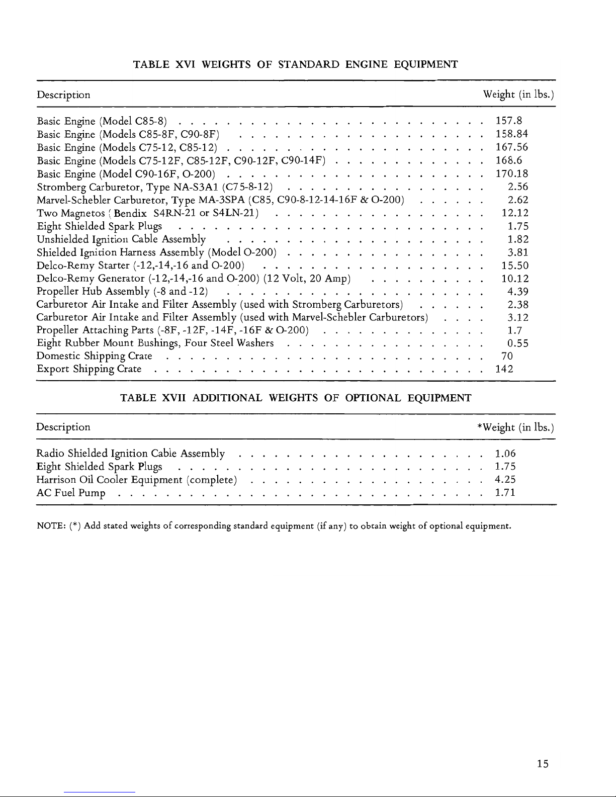
TABLE XVI WEIGHTS
OF
STANDARD ENGINE EQUIPMENT
Description
Basic Engine (Model C85-8) . . . .
Basic Engine (Models C85-8F, C90-8F)
Basic Engine (Models C75-12, C85-12)
Basic Engine (Models C75-12F, C85-12F, C90-12F, C90-14F)
Basic Engine (Model C90-16F,
0-200)
. . . . . . . . .
Stromberg Carburetor, Type NA-S3Al (C75-8-12)
....
Marvel-Schebler Carburetor, Type MA-3SPA (C85, C90-8-12-14-16F &
0-200)
Two Magnetos (Bendix S4RN-21
or
S4LN-21)
Eight Shielded Spark Plugs
........
.
unshielded Ignition Cable Assembly
....
.
Shielded Ignition Harness Assembly (Model
0-200)
Delco-Remy Starter (-12,-14,-16
and
0-200)
Delco-Remy Generator (-12,-14,-16
and
0-200)
(12 Volt, 20 Amp)
Propeller Hub Assembly
(-8
and
-12)
."..........
Carburetor Air Intake
and
Filter Assembly (used with Stromberg Carburetors)
Carburetor
Air Intake
and
Filter Assembly (used with Marvel-Schebler Carburetors)
Propeller Attaching Parts (-8F, -12F, -14F,
-16F & 0-200)
Eight Rubber Mount Bushings,
Four
Steel Washers
Domestic Shipping Crate
Export
Shipping Crate . . . . . . . . . . .
TABLE XVII ADDITIONAL WEIGHTS
OF
OPTIONAL EQUIPMENT
Description
Radio Shielded Ignition Cable Assembly
Eight Shielded Spark Plugs
.....
Harrison Oil Cooler Equipment (complete)
AC Fuel Pump . . . . . . . . . . .
Weight (in lbs.)
157.8
158.84
167.56
168.6
170.18
2.56
2.62
12.12
1.75
1.82
3.81
15.50
10.12
4.39
2.38
3.12
1.7
0.55
70
142
*Weight (in lbs.)
1.06
1.75
4.25
1.71
NOTE: (*)
Add
stated
weights
of
corresponding standard equipment (if any)
to
obtain weight
of
optional equipment.
15
SECTION
III
GENERAL
DESCRIPTION
3-1.
DIFFERENCE
BETWEEN
MODEL
GROUPS.
Models within the C series are grouped according
to
rated
power,
the
groups being 75, 85
and
90.
These three model numbers are prefixed
by
the
series designation
"C".
Models in the
C7s
group
differ from
the
corresponding dash numbered
models in the
C8s
group only in calibration
of
the
carburetor installed. C90 models differ from
C7s
and
C8s
models in
the
design
of
several major parts
and accessories, including the crankshaft, camshaft,
crankshaft gear (in -8 models only), carburetor, oil
sump, connecting rods, pistons
and
valve springs.
The
0-200,
in
turn,
differs from C Series in
the
design
of
its crankcase, camshaft, crankcase cover,
carburetor and oil sump.
It
differs further in
that
shielded ignition
is
standard equipment.
As
indicated in Table III, C90
and
0-200
models have
a longer piston stroke, resulting in a higher
compression ratio
and
larger piston displacement.
A higher fuel octane rating is required
by
these
features.
3-2. SIGNIFICANCE
OF
C SERIES DASH
NUMBERS AND LETTERS
Following
the
series letter
and
power
designati~n,
and
separated from
them
by
a dash, a figure and, in
some instances, a suffix letter
or
two in
the
complete model number denote the installation
of
certain parts
or
equipment designed
to
adapt
the
basic engine
to
various classes
of
aircraft. Those
dash numbers
and
suffix letters which have been
used
to
identify production models built
to
date
are as follows:
16
-8: No provisions for starter
or
generator.
-12: Starter, generator
and
associated parts
installed.
-14: Lord Engine Mount Bushings installed.
Otherwise like -12 models.
-16: Vacuum Pump Adapter. Otherwise like
-12 models.
F:
Flange
type
crankshaft installed (replaces
tapered shaft).
H: Crankcase
and
crankshaft
adapted
to
feed
oil
to
hydraulic controllable
pitch
propeller.
Various combinations
of
the foregoing dash
numbers
and
suffix letters are used
to
describe
equipment
of
the
different models. In the
following discussions
and
instructions
the
term
"-12 models" will indicate all models equipped
with
starter
and
generator, whether
or
not
they
have flange crankshafts (1.2F). The absence
of
a
suffix
letter
in
the
model number,
as
C7S-12,
indicates
that
a tapered crankshaft
is
installed. The
Lord
mount
bushing equipment
of
C90-14
and
0-200
models is illustrated in Figure 16.
3-3. MODEL CONVERSIONS.
Conversion
of
C7s
and
C8s
models
to
corresponding dash numbered C90 models is
not
approved, due
to
the nature
and
extent
of
parts
differences
and
to
the
possibility
of
unsatisfactory
results.
It
is
not
possible
to
convert any -8 model
to
a -12 model, because the -8 crankcase
is
not
adaptable
to
the
-12 crankcase cover in several
respects. Conversion
of
-12 models
to
-8 models is
not
approved for similar reasons. Neither -8
nor
-12
models can be converted
to
-14 models in the field
because
of
the
special machining required for Lord
mount
bushings. Conversion
of
C7s
models
to
corresponding dash numbered
C8s
models may be
accomplished in accordance with instructions
contained in
our
Service Bulletin on this subject.
Installation
of
a flange crankshaft in place
of
tapered shaft is considered merely a crankshaft
replacement
and
does
not
require factory approval
or
special instructions, however, engine
identification plates bearing model
or
dash
numbers,
other
than
those originally assigned,
cannot be issued unless an application for conver-
sion approval has been submitted and approved
by
the
factory Service Department.
3-4. OPTIONAL EQUIPMENT.
While
the
assignment
of
model numbers, as
described above, represents an
attempt
to
establish
categories
of
engines
of
the
same basic design
and
to
denote
the
equipment
installed, any extension
of
the
list
of
model numbers,
intended
to
specify
in detail
the
optional parts installed
to
adapt
engines
to
all aircraft installations, would
be
of
little
or
no
value, since these requirements change
frequently,
and
since optional
equipment
may
be
replaced
by
other
parts in
the
field. Accordingly,
engines are equipped
with
certain optional types
of
part,
such as oil sumps, accessories,
and
equipments (or systems), such
as
radio shielded
ignition,
as
specified
by
the
purchaser,
and
no
attempt
is made
to
denote
such installations in
the
engine model designation. Unshielded ignition
systems are standard
equipment
on
all C series
engines. Shielded ignition systems are standard
on
the
0-200.
Stromberg
type
NA-S3Al carburetors
are standard
on
all C75, C85
and
earlier C90
engines
and
are designed for gravity feed. Type
NA-S3Al carburetors designed for use
with
pump
feed systems are available. Marvel-Schebler
type
MA-3SPA carburetors are standard for
0-200
and
current
production
C90 engines. Oil sumps are
shaped
to
suit various aircraft in regard
to
location,
capacity
and
length
of
the
Hller neck.
The
oil gage
rod
assemblies are located in
the
oil filler neck
and
are marked per customer's specification for
capacity.
3-5.
SUPERSEDING PARTS.
Whenever possible, parts
of
improved design are
made
to
fit
into
existing engines so
that
modernization
of
older assemblies requires
replacement
of
only
the
redesigned part. This
is
not
always possible, because some parts are so
related
that
a change in
one
necessitates a
corresponding change in
the
other. Service
Bulletins list serial numbers
of
engines which
require new
type
parts for modernization. When a
superseding part
is
not
interchangeable with
the
original
type
of
part,
the
old
style
part
is
kept
in
stock for maintenance
of
the
older engines.
3-6. CRANKCASE CONSTRUCTION.
Aluminum alloy castings which form
the
left
and
right halves
of
the
crankcase are machined flat
and
smooth
along their parting surfaces. Upper
and
lower flanges are
attached
by
fourteen
hex
head
screws, washers,
and
plain nuts,
two
of
which
also
attach
the
engine lifting eye
to
the
upper
flanges. Each casting has
two
cylinder
mount
pads machined in its vertical side. Cylinder
openings in pads
on
the
two
sides
of
the
case are
not
quite opposite. Each casting has a heavy lateral
web
at
the
rear,
another
near
the
center
and a third
near
the
front. These webs are
cut
out
for
ventilation
and
oil drainage
and
have enlarged
bosses
at
the
case parting surface for crankshaft
and
camshaft bearings. Seats for steel backed,
preclSlon inserts
of
the
crankshaft main bearings
are line
bored
through
the
web bosses,
and
camshaft bearings are
bored
directly in
the
case
metal. These bearings are all divided equally
by
the
parting surface, camshaft bearings being directly
below
the
main bearings. Earlier case halves
of
the
C series engines are prevented from spreading
by
eight
through
studs installed in
the
bosses above
and
below
the
main bearings
and
one
stud
below
the
rear camshaft bearing. Current
production
C
series
and
all
0-200
case halves are retained
by
six
through
studs installed in
the
bosses above and
below
the
front
and
rear main bearings,
two
through bolts installed in lieu
of
the
two
through
studs
at
the
center
bearing bosses
and
one
through
stud
below
the
rear camshaft bearing. In addition
to
the
through
studs or
through
bolts, cylinder
mount
pads have short studs
to
make a
total
of
six
in each. Cylinder pads
and
case webs are stiffened
by
ribs cast inside
the
case. A
counterbore
around
the
crankshaft opening in
the
front
of
the
case
receives
the
crankshaft oil seal.
In
current
production
crankcases,
the
shoulder
behind
the
oil
seal recess
is
deeper
than
in older cases
to
make a
better
oil baffle.
The
long boss for
the
front
main
bearing in early C series
production
cases
had
two
dowels, driven through longitudinal holes
on
the
horizontal centerline,
to
engage holes
at
the
mid-points
of
semi-circular
thrust
washers which
were installed
at
front
and
rear ends
of
the
bearing.
In
later C series crankcases,
the
two
halves
of
each
washer were different. One
half
had a short
rivet
at
its mid-point
to
fit
into a notch
in
the
bearing boss.
The
other
half
was plain. These washers were
installed
with
the
split perpendicular
to
the
case
parting surface, whereas
the
original
type
washer
split was in line with
the
parting surface.
A groove has been
added
to
each
end
of
the
front
main bearing boss
to
accomodate
thrust
washers
on
the
0-200.
Old
style cases
not
having this groove
must be serviced
with
flanged
front
main bearings.
17
A
notch
is
provided
to
accept
the
tang
of
these
bearings. Below each cylinder pad,
and
on
the
horizontal plane
of
the
camshaft,
two
lateral bosses
inside
the
case are
bored
to
form valve lifter guides.
These bores emerge
at
the
case side surface,
and
a
pushrod housing adapter, installed over their
open
ends,
is
retained
by
three case studs
and
nuts.
Between
the
line
of
lifter guides
and
the
line
of
cylinder openings at each side
of
the
case are
the
main oil galleries extending from front
to
rear.
The
oil galleries are plugged
at
the front. Current
C series crankcases use a 5/8-18
hex
head
plug
and
annular gasket. Earlier C series
and
current
0-200
crankcases use (2)
3/8
NPT
countersunk
hex
pipe
plugs.
An
enlargement
of
each casting's lower
parting flange
at
the
front
end
forms
half
of
a boss
which
is
machined
and
studded
to
make a
mount
pad
for a vacuum
pump
on
the
-16
and
0-200.
A
semicircular flange
at
the
rear
of
the
crankcase
bottom
surface
is
machined flat
and
studded
to
form the
front
half
of
the
oil sump
mount
pad.
Two
studs driven
into
bosses
at
the
lower parting flanges are used for
attachment
of
the
intake manifold. The crankcase
breather
elbow
is
screwed
into a tapped
boss ahead
of
No. 3
cylinder.
An
upper
and
a lower arm
at
the
rear
of
each case casting affords an engine
mounting
point.
For
-8, -12
and
-16 models the
end
bosses
of
mounting
arms have
front
and
rear conical recesses
for
rubber
mount
bushings. The arm bosses
of
-14
and
0-200
model crankcases are
bored
through
and
counterbored
for Lord
mount
bushing assemblies.
Parts
of
the
Lord
mount
assembly are illustrated
in
Figure 16. The flange surrounding
the
rear
end
of
the crankcase
is
machined flat
and
studded
for
attachment
of
the crankcase cover. Locations
and
lengths
of
the
studs are different in
-8
and
-12
crankcases. The crankcase
of
-12, -14, -16
and
0-200
models has a hole
bored
through
the rear
web above
the
rear main bearing
to
hold
the
starter
pinion pivot. A dowel driven
into
the
left side
of
the
hole fits
into
the
pivot
to
hold
it
in position.
Some models have a
studded
mount
pad
for a fuel
pump
on
the
1-3 side
of
crankcase.
3-7. CRANKSHAFTS
Each
type
of
crankshaft
is
machined from a single
forging. The four crankpins are spaced
1800 apart.
Starting at
the
rear
and
proceeding forward,
the
crankpin numbers are 1, 2, 3
and
4, according
to
the
cylinders which
they
serve. Each crankshaft has
three main journals, the front one being
immediately ahead
of
No.4
front crankcheek. The
cheek
is
ground flat
around
the
journal
and
contacts the rear crankcase
thrust
washer
to
18
transfer propeller
thrust.
A small anti-thrust flange
at
the
front
end
of
the
front
journal
acts
as
an oil
slinger.
I
CAUTION
~
I
This design should
not
be used in
pusher
installations.
Older types
of
shaft
had a taper
on
the front side
of
the slinger flange. These
cannot
be installed in pres-
ent type crankcases because
of
interference between
the
taper
and
the case oil baffle.
The
slinger flange
of
present type cranksh,afts has parallel sides. All
crankshafts
are
center bored for lightness.
The
front
bore runs
out
at
the
front crankcheek
and
the
rear
end bore
at
the
rear crankcheek. Steel oil tubes
are
permanently installed in holes drilled from
the
front
and
rear journals
through
crankcheeks
to
Nos. 1
and
4 crankpins. Oil holes are drilled
through solid cheeks from the center
journal
to
Nos. 2
and
3 crankpins. The
tapered
type
shaft has
a slot along the propeller
hub
taper
for a square key
to
drive the steel
hub
used with it.
The
hub
fits
tightly
on
the
taper
and
is
retained by a
tube
nut,
which
is
locked by a flat head pin. A snap ring in a
hub
groove ahead
of
the
nut
flange acts
as a hub
puller.
The
propeller
is
clamped between
the
steel
hub
flange
and
a loose steel flange in
front
by six
bolts
and
nuts. The flange
type
shaft has a
propeller
mount
flange forged
on
its
front
end
with
six
tapped
bushings pressed
into
holes spaced
equally
around
the flange. Six bolts, screwed
into
the
shaft flange bushings, clamp
the
propeller
between a loose
front
flange
and
the
shaft flange.
The loose
front
flange
and
the
six bolts are
not
supplied as part
of
the
0-200
engine. A steel cased
oil seal
is
installed over
the
front
end
of
tapered
shafts
and
is
retained
in
the crankcase recess
around
the
shaft opening. With flange
type
crankshafts a split, composition seal
is
used.
It
is
made in one piece,
and
the
seal lip
is
held against
the shaft race
by
a spring. The gear pilot flange
at
the rear
end
of
the
crankshaft has four unequally
spaced
tapped
holes for gear retammg screws.
Current
production
shafts have a dowel between
two
of
the
screw holes.
3-8.
NITRIDED
CRANKSHAFTS
Latest
types
of
flanged
and
tapered
crankshafts
have nitrided main journals
and
crank
pins. Flange
shafts
for
C90
and
0-200
models have always
been
nitrided. These are identified
by a 1/4
inch hole
drilled
through
the
propeller
mount
flange.
Nitrided flange
type
shafts
for
C75
and
C85
models are identified
by
the
letter
"N"
stamped
on
the edge
of
the
propeller flange. Tapered shafts for
C7S
and
C8S models,
if
not
nitrided, have four
hub
nut
lock pin holes
at
the
front end. One additional
hole
is
drilled
to
identify nitrided shafts.
3-9. CRANKSHAFT GEARS
The
gear is piloted
on
the
small rear flange
of
the
crankshaft
and
aligned
by
the
crankshaft dowel.
It
is
retained
by
four screws. Screw holes are
unequally spaced
to
assure correct installation. The
space between
two
adjacent punch marked gear
teeth
points
to
the camshaft when
No.1
crankpin
is
at
T. D. C. Gears for -8 models are plain spur
gears. In -12, -16 and
0-200
models a cluster gear
is
installed. Its large wheel has beveled
teeth
and
is
driven
by
the
starter pinion.
3-10.CONNECTING RODS
Connecting
rod
assemblies
of
C90
and
0-200
models differ in dimensions from those
of
C7S
and
C8S models,
but
the
two
types are
of
similar
design.
The
rod
and
bearing cap assembly are made
from a single steel alloy forging, which is sawed
through the center
of
the big
end
before the
bearing seat is bored. Each
half
of
the
split big
end
bore
is
notched
to
accept
the
tang
of
the
semicircular bearing insert which fits in it. The
replaceable crankpin bearing inserts are
thin
steel-back shell type, lined
with
special alloy metal.
The
bearing cap is attached
to
the
rod
by
two
special bolts
and
hex
nuts. The cylinder number
is
stamped
on
the upper
bolt
boss
of
both
rod
and
cap. A tapered
"I"
beam connects
the
big
end
and
the piston pin boss. The piston pin bushing
is
a
plain bronze sleeve, pressed
into
the
rod
boss
and
bored
parallel
to
the big end bearing.
The
original
type solid piston pin bushing has been replaced
by
a single piece, split type bushing in
both
C7S, C8S,
C90
and
0-200
type rods.
3-11. CAMSHAFTS
All camshafts installed in C7S
and
C8S models are
flame hardened iron castings. The same material
was employed in early production C90 camshafts.
Present
type
C90
and
the original
0-200
camshafts
are alloy steel forgings. These are identified, when
new,
by
an over-all black Parko-Lubrite coating
and
an underlying copper plate
on
unfinished
surfaces. All C90
and
0-200
camshafts are reduced
in diameter between cam lobes
to
provide
connecting
rod
clearance. Standard camshafts for C
series carburetor engines have an eccentric
machined
at
the front fuel
pump
lever. A special
camshaft
with
two
eccentrics
is
available for
installations which require a second fuel pump.
Camshafts installed
with
vacuum
pump
equipment
in -16
and
0-200
engines have
no
pump
drive
eccentric.
The
front
end
of
this type has six
tapped
holes for screws which
attach
the vacuum
pump
drive bevel gear. A special combination gear
and
eccentric is also available for
the
vacuum
pump
and
side
mounted
fuel pump. The C90-16
and
0-200
also have a camshaft for a side
mounted
fuel
pump
with
no
provision for a vacuum drive gear. The gear
is
spaced from
the
shaft end, for correct backlash
with
the
vacuum
pump
gear,
by
one
or
more shims,
which are available in
two
thicknesses. A few
of
the
early
production
0-200
engines have these
shims installed. Current production engines do
not
require these shims
to
provide proper backlash. All
camshafts have three journals. The center
journal
is
plain, while the front
journal
has a deep groove
to
register with oil holes drilled from its bearing
into
the
main oil galleries.
The
rear
journal
has flanges
at its
front
and
rear ends
to
restrict camshaft
end
movement
in
the rear bearing.
The
rear flange has
four unequally spaced
tapped
holes for
the
camshaft drive gear retaining screws. Three cam
lobes between each
two
journals operate valve
lifters for
two
cylinders. In each group,
the
outer
lobes each operate one exhaust valve lifter,
and
the
center lobe operates two opposite intake valve
lifters. Lobes
of
0-200
camshafts have a greater lift
than others.
3-12. CAMSHAFT GEARS
Camshaft drive gears installed in -8 models are
single spur gears with the web at the rear, while
those in -12, -14, -16
and
0-200
models have
both
external
and
internal
teeth,
and
the web is at
the
front. The internal
teeth
drive
the
generator gear.
Both types
of
gears have a square hole in
the
center
to
receive
the
oil
pump
driving impeller shaft. A
ground recess in the front side
of
each gear web fits
closely over the camshaft pilot flange. The gear is
retained
by
four hex head screws in holes spaced
unequally
around
the web. Thus, the gear can be
installed in only one position in relation
to
the
cam
lobes. A
punch
marked
tooth
is meshed,
at
assembly, between
two
similarly marked
teeth
on
the
crankshaft gear,
and
this simple operation
assures correct valve timing
without
measurement.
19
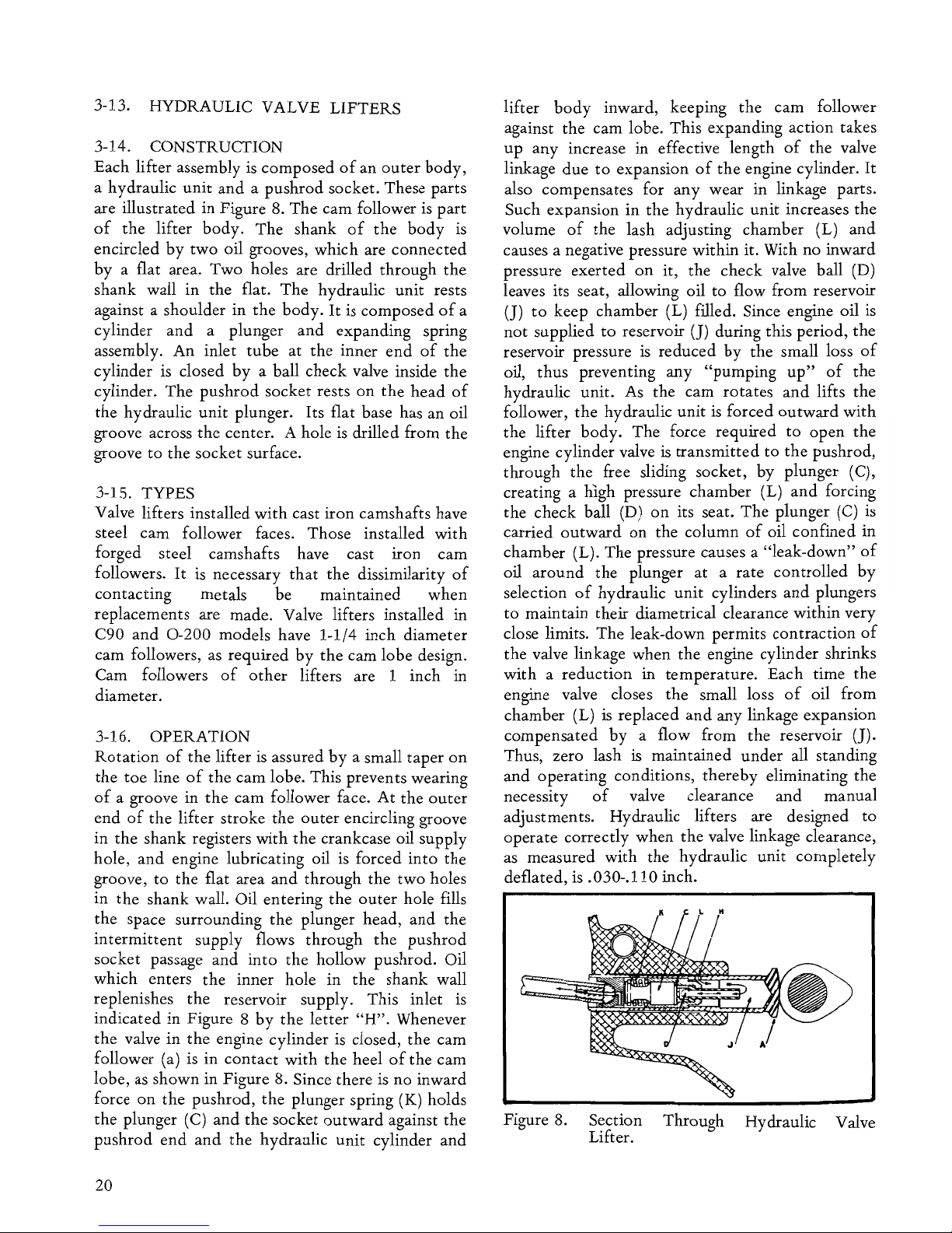
3-13. HYDRAULIC VALVE LIFTERS
3-14. CONSTRUCTION
Each lifter assembly
is
composed
of
an
outer
body,
a hydraulic
unit
and
a pushrod socket. These parts
are illustrated in Figure 8. The cam follower
is
part
of
the
lifter
body.
The
shank
of
the
body
is
encircled
by
two
oil grooves, which are
connected
by
a flat area. Two holes are drilled through
the
shank wall in
the
flat.
The
hydraulic
unit
rests
against a shoulder in
the
body.
It
is composed
of
a
cylinder
and
a plunger
and
expanding spring
assembly. An inlet
tube
at
the
inner
end
of
the
cylinder
is
closed
by
a ball check valve inside
the
cylinder.
The
pushrod socket rests
on
the
head
of
the
hydraulic
unit
plunger. Its flat base has an oil
groove across
the
center. A hole
is
drilled from
the
groove
to
the
socket surface.
3-15. TYPES
Valve lifters installed
with
cast iron camshafts have
steel cam follower faces. Those installed
with
forged steel camshafts have cast
iron
cam
followers.
It
is
necessary
that
the
dissimilarity
of
contacting metals be maintained
when
replacements are made. Valve lifters installed in
C90
and
0-200
models have 1-1/4 inch diameter
cam followers,
as
required
by
the
cam lobe design.
Cam followers
of
other
lifters are 1 inch in
diameter.
3-16. OPERATION
Rotation
of
the
lifter
is
assured
by
a small
taper
on
the
toe
line
of
the
cam lobe. This prevents wearing
of
a groove in
the
cam follower face.
At
the
outer
end
of
the
lifter stroke
the
outer
encircling groove
in
the
shank registers
with
the
crankcase oil supply
hole, and engine lubricating oil
is
forced
into
the
groove,
to
the
flat area
and
through
the
two
holes
in
the
shank wall. Oil entering
the
outer
hole fills
the
space surrounding
the
plunger head,
and
the
intermittent
supply flows through
the
pushrod
socket passage
and
into
the
hollow pushrod. Oil
which enters
the
inner hole in
the
shank wall
replenishes
the
reservoir supply. This inlet
is
indicated in Figure 8
by
the
letter
"H".
Whenever
the
valve in
the
engine cylinder is closed,
the
cam
follower (a) is in
contact
with
the
heel
of
the
cam
lobe,
as
shown in Figure 8. Since there
is
no inward
force
on
the
pushrod,
the
plunger spring
(K)
holds
the
plunger
(C)
and
the
socket
outward
against
the
pushrod
end
and
the
hydraulic
unit
cylinder
and
20
lifter
body
inward, keeping
the
cam follower
against
the
cam lobe. This expanding action takes
up
any increase in effective length
of
the
valve
linkage due
to
expansion
of
the
engine cylinder.
It
also compensates for
any
wear in linkage parts.
Such expansion
in
the
hydraulic
unit
increases the
volume
of
the
lash adjusting chamber (L)
and
causes a negative pressure within it. With no inward
pressure
exerted
on
it,
the
check valve ball (D)
leaves its seat, allowing oil
to
flow from reservoir
(J)
to
keep chamber (L) filled. Since engine oil
is
not
supplied
to
reservoir
(J)
during this period,
the
reservoir pressure
is
reduced
by
the
small loss
of
oil,
thus
preventing any
"pumping
up"
of
the
hydraulic unit. As
the
cam rotates
and
lifts
the
follower,
the
hydraulic
unit
is
forced
outward
with
the
lifter
body.
The force required
to
open
the
engine cylinder valve
is
transmitted
to
the
pushrod,
through
the
free sliding socket,
by
plunger (C),
creating a high pressure chamber (L)
and
forcing
the
check ball (D)
on
its seat.
The
plunger (C) is
carried
outward
on
the
column
of
oil confined in
chamber (L).
The
pressure causes a
"leak-down"
of
oil
around
the
plunger
at
a rate controlled
by
selection
of
hydraulic
unit
cylinders
and
plungers
to
maintain their diametrical clearance within very
close limits.
The
leak-down permits
contraction
of
the
valve linkage when
the
engine cylinder shrinks
with
a reduction in temperature. Each time
the
engine valve closes
the
small loss
of
oil from
chamber (L)
is
replaced
and
any linkage expansion
compensated
by
a flow from
the
reservoir (J).
Thus, zero lash
is maintained under all standing
and
operating conditions,
thereby
eliminating
the
necessity
of
valve clearance
and
manual
adjustments. Hydraulic lifters are designed
to
operate correctly when
the
valve linkage clearance,
as
measured
with
the
hydraulic
unit
completely
deflated, is .030-.110 inch.
Figure 8.
Section Through Hydraulic Valve
Lifter.
3-17. PUSHRODS AND HOUSINGS.
Each pushrod
is
made by pressing a hardened steel
ball
end
into
each
end
of
a steel tube. Ball ends are
drilled through
on
the tube axis for oil passage.
Each pushrod
is
surrounded by a thin, tubular steel
housing,
two
of
which are permanently installed in
the
downward extension
of
each cylinder rocker
box. A cast aluminum adapter,
attached
to
the
crankcase
by
three studs
and
nuts,
is
located below
each cylinder. Two pushrod housings are sealed
to
each adapter by rubber "connections and hose
clamps.
3-18. PISTON ASSEMBLIES
The
solid
trunk,
flat head pistons are machined
aluminum alloy castings. Those in
C7
Sand
C8S
models have four ring grooves above
the
pin, while
C90
and
0-200
pistons have three rings above
the
pin
and
one
below. The upper three compression
rings are similar in
both
types
of
piston. The
top
ring
is
faced with
hard
chrome
to
withstand heat.
The second and
third
are plain cast iron rings.
The
faces
of
all these are tapered inward
toward
the
top
so
that
wear
and
seating begin
at
the
bottom,
providing good scraping action
and
quick seal.
Center slotted oil
control
rings in
the
bottom
grooves are slightly different in
the
two
types
of
piston assembly. Piston pins are seamless steel
tubes, ground
on
the
outside
and
fitted
with
aluminum
end
plugs
to
space
them
from,
the
cylinder walls. Original
type
pin assemblies
had
removable
end
plugs.
End
plugs
of
current
production
pins are pressed in before final grinding
and
are
not
replacable. This
type
of
pin assembly
must be used for all replacements. Pins are a push
fit in piston bores.
3-19. CYLINDER ASSEMBLIES
3-20. CYLINDER AND HEAD
Externally finned aluminum alloy head castings are
screwed and shrunk permanently
on
externally
finned steel barrels. The rocker
box
cast in
the
outer
end
of
the head has a surrounding flange
which is machined flat. The pressed steel rocker
cover is sealed
to
the
flange
by
a soft gasket
and
retained
by
six fillister head screws. Three bosses
cast in
the
rocker
box
are
bored
in a horizontal line
at
right angles
to
the
cylinder axis
to
form rocker
shaft supports. Valve ports in
the
head open
downward
into
two flanges, each provided with
two studs. Bronze guides for intake
and
exhaust
valves are pressed into holes
bored
from the
bottom
of
the
rocker
box
into
the
valve chambers
in line with
the
valve seats. Alloy steel exhaust
valve seat inserts
and
aluminum bronze intake
valve seat inserts are shrunk
into
counterbores
i
nth
e combustion chamber surface. Early
production cylinders
had
threaded spark plug
inserts screwed and pinned in
tapped
holes above
and below the valve seats.
Use original piston with original cylinder
or
replace
spark
plug bushing with helicoil
when using current piston in original
cylinder.
Current
production
cylinders incorporate helical
coil type inserts. A
1/8
inch pipe
tapped
hole
through
the
upper
wall
of
the intake valve
chamber
of
earlier
production
cylinders
is
intended for a
primer jet, which may be installed by
the
owner.
The
hole
is
normally sealed by a countersunk hex head
pipe plug.
An
external base flange below
the
cylinder barrel fins
is
ground
flat
and
drilled for the
six crankcase studs,
to
which
the
assembly
is
attached by flanged hex nuts.
From
the base flange,
the cylinder skirt extends inward
through
the
crankcase wall opening, as a pilot. A
rubber
packing
ring, placed
around
the cylinder skirt
and
against
the flange,
is
compressed in a chamfer
around
the
pad
opening
and
prevents oil leakage.
Two
tubular
steel
pushrod
housings are swelled into holes in the
downward extension
of
the
rocker
box
and
lie below
the cylinder.
3-21.
VALVES
Both
intake
and
exhaust valves are a modified tulip
design.
The
head
of
the
intake valve
is
marked
"IN",
and
the
exhaust valve head
is
marked
"EX".
The
tip
of
each valve stem
is
hardened
and
ground
flat and square
with
the
stem surface. Near the tip,
a groove
is
cut
in
the
stem
to
engage
the
split lock.
The face
of
the
exhaust
valve has a
3/64
inch
minimum thickness
of
No. 6 Stellite welded
on
to
withstand heat.
3-22. VALVE SPRINGS
An inner valve spring retainer
of
pressed steel
is
installed over each valve guide
and
seated
on
the
rocker
box
bottom
to
center the valve springs
and
prevent wear
on
the
aluminum head surface. One
inner
and
one
outer
spring fit in each retainer,
surrounding
the
valve stem. They are retained
by
outer
spring seat
of
steel, whose conical center hole
fits over
the
valve stem
and
is
engaged
to
it
by
the
split locks. Each valve in C90
and
0-200
cylinders
has three springs.
21
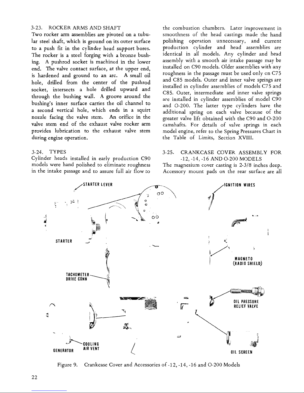
3-23. ROCKER ARMS AND SHAFT
Two rocker
ann
assemblies are pivoted
on a tubu-
lar steel shaft, which
is
ground
on
its
outer
surface
to
a push fit in
the
cylinder
head
support
bores.
The rocker· is a steel forging
with
a bronze bush-
ing. A pushrod socket
is
machined in
the
lower
end. The valve
contact
surface,
at
the
upper
end,
is
hardened
and
ground
to
an arc. A small oil
hole, drilled from the center
of
the pushrod
socket, intersects a hole drilled
upward
and
through
the
bushing wall. A groove around
the
bushing's inner surface carries
the
oil channel
to
a second vertical hole, which ends in a squirt
nozzle facing
the
valve stem.
An
orifice in
the
valve stem
end
of
the
exhaust valve rocker
ann
provides lubrication
to
the exhaust valve stem
during engine operation.
3-24.
TYPES
Cylinder heads installed in early production C90
models were hand polished
to
eliminate roughness
in
the
intake passage
and
to assure full air flow
to
/STARTER
LEVER
o·
STARTER
TACHOMETER
DRIVE
CONN
GENERATOR
the combustion chambers. Later improvement in
smoothness
of
the head castings made the hand
polishing operation unnecessary, and current
production cylinder
and
head assemblies are
identical in all models. Any cylinder
and
head
assembly with a smooth air intake passage may be
installed
on
C90 models. Older assemblies with any
roughness in the passage must be used only
on
C75
and
C85 models. Outer
and
inner valve springs are
installed in cylinder assemblies
of
models C75
and
C85. Outer, intermediate
and
inner valve springs
are installed in cylinder assemblies
of
model C90
and
0-200.
The latter type cylinders have
the
additional spring
on
each valve because
of
the
greater valve lift obtained with the C90
and
0-200
camshafts.
For
details
of
valve springs in each
model engine, refer
to
the Spring Pressures Chart in
the Table
of
Limits, Section XVIII.
3-25. CRANKCASE COVER ASSEMBLY
FOR
-12, -14, -16 AND
0-200
MODELS
The magnesium cover casting
is
2-3/8 inches deep.
Accessory
mount
pads on the rear surface are all
MAGNETO
(RADIO
SHIELD)
OIL
PRESSURE
RELIEF
VALVE
Figure 9. Crankcase Cover
and
Accessories
of-12,
-14, -16
and
0-200
Models
22
machined in one plane parallel
to
the machined
parting flange which surrounds the
front
side
of
the casting. Locations
of
the pads
and
methods
of
accessory
attachment
are illustrated in Figure
9.
Two holes, drilled through
the
casting
at
the
top,
are for
the
bolts which
attach
the
starter adapter to
the crankcase rear flange. Central openings in
magneto
mount
pads admit the magneto drive
gears
and
locate
the
magneto pilot shoulders. The
tachometer drive housing
is
attached
by
three studs
and
nuts over a gasket which also covers the
generator
mount
pad. The tachometer drive shaft
is
the
slotted rear
end
of
the oil
pump
driven impeller
shaft. The tachometer drive housing has an
external
thread
for the drive conduit nut. A steel
cased oil seal
is
pressed
into
the
front
end
of
the
housing. Its seal lip contacts
the
tachometer
drive
shaft ahead
of
the
slot. Below
the
tachometer drive
shaft hole, a second hearing
is
bored
throught
the
cover rear wall for the oil
pump
driving impeller
shaft. The oil
pump
impeller chambers are
machined in
the
front side
of
the cover rear wall in
line
with
the
shaft holes. An aluminum cover
is
attached
over
the
open front
end
of
the
pump
chambers
by
four screws. The squared front
end
of
the driving impeller shaft projects forward
throught
the
pump
cover
to
engage
the
square hole
in
the
center
of
the camshaft gear. The generator
mount
pad has
two
short studs
and
a hole for one
of
the crankcase studs. The generator
is
attached
to
these three studs
by
elastic stop nuts. The gear
opening is counterbored
to
fit
the
generator pilot
shoulder.
The
oil screen housing
is
attached, over a
triangular gasket,
by
nuts installed on a short stud,
driven
into
the pad,
and
two
long crankcase studs,
which project through holes in
the
cover. The
bottom
of
the
cover casting
is
a semicircle, open
at
the front, with a surrounding flange, which
is
machined
and
studded
to
finish the rear
half
of
the
oil sump
mount
pad.
The
oil
pump
suction
tube
is
screwed
into
the
bottom
cover wall within
the
semicircle
and
is sealed
by
a copper-asbestos
gasket. A screen
is
permanently
attached
over
the
lower
tube
end, which lies below the sump oil
level. A cored passage in the cover casting extends
from
the
upper
end
of
the
suction tube
to
the
oil
pump
inlet.
From
the delivery
port
of
the pump, a
second cored passage extends
to
the
right
and
surrounds
the
oil screen opening.
The
screen cap
is
screwed
into
the screen housing over a
copper-asbestos gasket. The oil screen
is
permanently
attached
to
the
cap
and
is
reinforced
by
a ferrule
at
its open
front
end. The ferrule fits
closely in a hole
bored
in
the
front wall
of
the
oil passage.
From
the screen outlet,
another
passage
in the cover leads
to
a hole drilled in
the
cover
parting flange in register with the crankcase oil
inlet. In line with
the
crankcase right oil gallery, a
hole
is
drilled from the cover casting parting flange
rearward.
An
intersecting hole
to
the
right ends in
an open cavity within
the
hollow boss for
the
oil
pressure relief valve. The valve plunger seats on
the
end
of
the
drilled hole.
It
is
guided in a bronze cap,
which
is
screwed
into
the boss,
and
is
held
on
its
seat
by
a spring. A drilled
and
tapped
hole
on
the
left side
of
the
0-200
crankcase cover ends in
the
cored passage
on
the
suction side
of
the
oil
pump
and
provides an oil
return
from the vacuum pump.
3-26. CRANKCASE COVER ASSEMBLY
FOR
-8 MODELS
The magnesium cover casting
is
1-5/32 inches deep
at
the
magneto
mount
pads, while the integral oil
screen housing, at the left side, extends 3-11/16
inches from the parting flange,
and
the central boss
for
the
tachometer drive housing extends 3-3/8
inches.
The
bottom
of
the casting
is
similar
to
that
of
the
cover
to
-12 models,
and
the oil
pump
suction tube is
attached
in the same manner. Cored
passages connect the suction tube
to
the oil pump
inlet
and
the
pump
outlet
to
the oil screen cavity.
The squared front end
of
the
oil
pump
driving
impeller extends through
the
pump
cover
and
into
the
square hole in
the
camshaft gear. The rear
end
of
the
driving impeller
is
the
tachometer drive
shaft. The tachometer drive housing
is
screwed
into
a left
hand
thread in the cover boss. An oil seal
pressed
into
the
front
of
the housing rides
on
the
tachometer drive shaft. The oil screen
and
pressure
relief valve assemblies are the same
as
installed in
-12, -14, -16
and
0-200
models. The cover passage
from
the
screen leads
to
the
left oil gallery.
The
pressure relief valve closes
the
rear
end
of
a hole
drilled from
the
cover flange, in line with
the
right
oil gallery,
to
the gear cavity.
3-27. GEAR TRAIN (See Figure 10)
The crankshaft gear (1)
is
rotated
in a clockwise
direction
by
the crankshaft. The small gear section
of
the
crankshaft gear mates with
and
drives, at
1/2
crankshaft speed,
the
camshaft gear (2).
For
-8
models
the
crankshaft gear also drives the magneto
gears direct in a counterclockwise direction. The
magneto gears (3), oil
pump
driver gear (4)
and
23
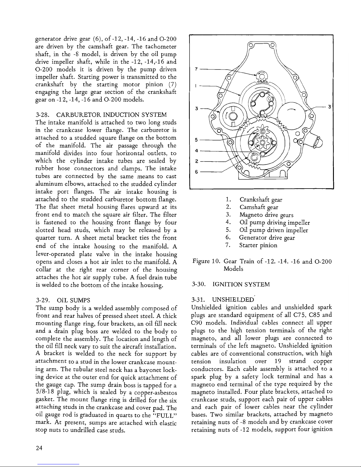
generator drive gear (6),
of
-12, -14, -16
and
0-200
are driven
by
the camshaft gear. The tachometer
shaft, in
the
-8 model, is driven
by
the oil
pump
drive impeller shaft, while in the -12, -14,-16
and
0-200
models it
is
driven by the
pump
driven 7
------.6:
impeller shaft. Starting power
is
transmitted
to
the
crankshaft
by
the
starting
motor
pinion (7)
engaging
the
large gear section
of
the crankshaft
gear
on
-12, -14, -16
and
0-200
models.
3-28. CARBURETOR INDUCTION SYSTEM
The intake manifold
is
attached
to two long studs
in the crankcase lower flange. The carburetor is
attached
to
a studded square flange on the
bottom
of
the
manifold. The air passage through
the
manifold divides into four horizontal outlets,
to
which the cylinder intake tubes are sealed
by
rubber hose connectors
and
clamps.
The
intake
tubes are connected
by
the same means
to
cast
aluminum elbows,
attached
to
the studded cylinder
intake
port
flanges. The air intake housing
is
attached
to
the
studded
carburetor
bottom
flange.
The
flat sheet metal housing flares upward
at
its
front
end
to
match the square air filter. The filter
is
fastened to
the
housing front flange
by
four
slotted head studs, which may be released
by
a
quarter turn. A sheet metal bracket ties the front
end
of
the
intake housing
to
the
manifold. A
lever-operated plate valve in the intake housing
opens
and
closes a
hot
air inlet
to
the
manifold. A
collar at the right rear corner
of
the
housing
attaches
the
hot
air supply tube. A fuel drain
tube
is
welded
to
the
bottom
of
the intake housing.
3-29. OIL SUMPS
The sump
body
is
a welded assembly composed
of
front
and
rear halves
of
pressed sheet steel. A thick
mounting flange ring, four brackets, an oil fill neck
and
a drain plug boss are welded
to
the
body
to
complete
the
assembly. The location
and
length
of
the oil fill neck vary
to
suit the aircraft installation.
A bracket
is
welded to the neck for support
by
attachment
to
a stud in
the
lower crankcase mount-
ing arm. The tubular steel neck has a
bayonet
lock-
ing device at the
outer
end
for quick
attachment
of
the gauge cap. The sump drain boss
is
tapped
for a
5/8-18 plug, which
is
sealed
by
a copper-asbestos
gasket.
The
mount
flange ring
is
drilled for the six
attaching studs in the crankcase
and
cover pad. The
oil gauge
rod
is
graduated in quarts
to
the
"FULL"
mark.
At
present, sumps are
attached
with elastic
stop nuts
to
undrilled case studs.
24
3
5----H:;:;:..
2
----/
6---./
1. Crankshaft gear
2.
Camshaft gear
3. Magneto drive gears
4. Oil
pump
driving impeller
5. Oil
pump
driven impeller
6. Generator drive gear
7.
Starter pinion
Figure 10. Gear Train
of
-12. -14. -16
and
0-200
Models
3-30. IGNITION SYSTEM
3-31. UNSHIELDED
Unshielded ignition cables
and
unshielded spark
plugs are standard equipment
of
all C75, C85
and
C90 models. Individual cables connect all upper
plugs
to
the
high tension terminals
of
the right
magneto,
and
all lower plugs are connected
to
terminals
of
the
left magneto. Unshielded ignition
cables are
of
conventional construction, with high
tension insulation over 19 strand copper
conductors. Each cable assembly
is
attached
to
a
spark plug
by
a safety lock terminal
and
has a
magneto
end
terminal
of
the
type
required
by
the
magneto installed.
Four
plate brackets,
attached
to
crankcase studs, support each pair
of
upper cables
and
each pair
of
lower cables near the cylinder
bases. Two similar brackets,
attached
by
magneto
retaining
nuts
of
-8 models
and
by
crankcase cover
retaining nuts
of
-12 models, support four ignition
cables
on
each side
of
the
engine. A
rubber
grom-
met
in each
bracket
prevents chafing
of
the
cable
insulation. C90-8 models are equipped
with
Bendix S4RN-21 magnetos, and all C90-12, -14
and 0-200 models have Bendix S4LN-21
or
Slick
Series
4000
magnetos. C75, C85 models may also
have Bendix magnetos.
For
this
type
of
magneto,
all four cables are
attached
by
cable piercing screws
to
a removable terminal plate
and
grommet
assem-
bly, making a single cable assembly for each mag-
neto.
3-32. RADIO SHIELDED IGNITION SYSTEMS
Either
Eisemann LA-4, Bendix S4LN-20
or
Slick
Series
4000
magnetos
may
be
used
with
shielded
system where approved. (See Table IX). Radio
shielded ignition cables are assembled in pairs for
the
upper
right,
upper
left, lower right
and
lower
left
spark plugs.
The
brackets which
hold
together
the
two
cables in each assembly are
attached
to
crankcase studs. A wrapping
of
friction
tape
pre-
vents
the
old style
bracket
from
cutting
or
chafing
cable insulation. New brackets are neoprene
coated
to
prevent
cutting
or
chafing. Cable assemblies for
-8
and
-12 models
with
LA-4 magnetos have only
one
bracket
each.
An
additional
bracket
is
in-
stalled
on
the
bottom
starter retaining
stud
to
hold
upper
left
and
lower right spark plug cables away
from
the
starter clutch shaft. Shielded cable
assemblies for Bendix magnetos
of
-8 models have
one
bracket
on
each pair
of
cables,
and
for -12
models
they
have a second
bracket
on
each pair.
The
two
pairs
of
cables served
by
each magneto are
attached
to
the
terminal plate grommet
by
cable
piercing screws. All shielded cables are
equipped
with
spark plug elbows
and
contact
sleeves.
To
make
contact
with
other
shielding members,
the
outer
plastic wrap
of
the
cable
is
stripped for a
short
distance at each end,
and
the
sheath
of
braided
copper
wires
is
folded
back
to
make
a
cuff.
At
the
spark plug
end
a split lead cone
is
placed over
the
cuff
and
held in
the
elbow
by
a
union
nut.
At
the
magneto
end
a flanged ferrule
is
swaged
on
over the
cuff
and
is
held
to
the
mag-
neto
terminal plate
by
a coupling
nut.
3-33. SWITCH WIRE TERMINALS
The
AM-4 magneto has a
stud
terminal,
to
which
the
switch wire
is
attached
by
a hex
nut.
Shielded
magnetos have spring terminals within the breaker
housing,
and
switch wires must be
equipped
with
terminal assemblies consisting
of
contact,
insulators, ferrules
and
union
nut.
Wire terminal
assemblies are furnished with LA-4 magnetos,
Bendix terminal kits are sold separately
and
are
slightly different.
3-34. MAGNETO
DRIVE
GEARS
Eisemann AM-4 magnetos installed
on
the
left side
of
C85-8 models have impulse couplings,
but
those
on
the
right side are driven
by
a gear
mounted
directly
on
the
rotor
shaft. All Eisemann LA-4
Bendix S4N,
and
Slick magnetos have impulse
couplings. Drive gears for these magnetos are
centered
on
a sleeve
on
the
rotor
shaft,
and
they
are retained
by a nut
screwed
on
the
shaft,
but
they
are free
to a nut
screwed
on
the shaft,
but
they
are free
to
rotate
on
the
sleeve.
They
drive
the
impulse coupling barrel lugs, which fit
in
slots in
the
gear web.
The
type
of
gear installed
with
im-
pulse couplings
on
-12, -14, -16
and
0-200 models
extends further forward
than
the
type
installed
on
-8 models,
due
to
the
difference in crankcase cover
depth.
3-35. IMPULSE COUPLING OPERATION
The
impulse coupling performs
two
important
operations
to
facilitate starting, i.e.,
it
holds back
the
magneto
rotor,
just
before
the
breaker opening
position, while the drive gear continues its
rotation,
thereby
retarding
the
spark,
and
it
releases
the
rotor
approximately
at
T. D. C.
of
the
engine pistion, allowing
the
coupling spring
to
spin
the
rotor
rapidly through its neutral position,
opening the breaker
and
producing a
hot
spark at
cranking speed.
Two
counterweighted latches in
the coupling flange assembly provide
the
automatic
spark retard.
The
upper
latch
engages a
stud
in
the
housing
and
stops
rotation
of
the
flange
and
rotor
shaft.
Further
rotation
of
the
barrel (or drive cup)
winds
up
the
coupling spring until
the
barrel
contacts
the latch
and
forces
it
inward
and
clear
of
the
stud. Then, the spring spins
the
flange
and
rotor
through
neutral
to
produce
the
spark.
After
the
engine starts,
the
latch counterweights
hold
the
latch
pawls away from the stud,
and
the
coupling
spring drives
the
rotor
in
the
full advance position.
3-36. DELCO-REMY
STARTER
The
motor
and
clutch
of
the direct cranking
starter
are
mounted
on
an adapter plate,
by
which the
unit
is
attached
to
crankcase cover studs
and
through bolts. The
clutch
and
pinion assembly
25
bears in a Oilite bushing, pressed in a hole
bored
through
the
adapter below
the
motor. Another
Oilite bushing in
the
hollow clutch shaft bears
on
the
pivot held in
the
crankcase. A large gear
on
the
clutch shaft is driven
by
the
armature shaft gear.
The pinion is driven
by
the clutch shaft through an
over-riding clutch. A spring in
the
front end
of
the
clutch shaft
is
slightly compressed
by
the
pivot,
tending
to
disengage
the
starter pinion. A lever,
pivoted
on
the
motor
coil housing
and
operated
by
a cable from
the
cockpit, shifts the clutch shaft
forward, for starting,
and
the
pinion meshes
with
the
teeth
of
the large wheel
on
the
crankshaft
cluster gear. The starter switch
button
is
depressed,
to
close
the
electrical circuit,
by
the
shift lever.
The shift lever operates
the
clutch through a spring
cap
and
spring in
the
rear
end
of
the
clutch shaft,
so
that
the
clutch can be closed, even though
the
pmlOD
and
cluster gear
teeth
are
abutted.
Immediately
the
motor
turns, the pinion meshes.
3-37. PRESTO LITE STARTER
The Prestolite Starter
is
solenoid
actuated
and
employs a Formsprag Torque Limiting Drive which
is used with,
but
is
not
part of,
the
starter.
The
clutch assembly bears in a needle bearing pressed in
a hole
bored
through the adapter below
the
motor.
The
other
end
rides in a needle bearing pressed
into
the starter jackshaft adapter located in the
crankcase. As the solenoid
is
actuated,
by
the key
or
switch,
the
starter gear turns engaging a
gearshaft which activates a sprag pack in the clutch
assembly. The sprag pack expands and drives the
hub, which drives the idler gear and thereby the
crankshaft gear. When
the
engine fires
and
the
crank is running at a greater speed
than
the
starter,
the sprag pack is no longer driving
the
hub.
3-38.
GENERATOR/ALTERNATOR
AND
DRIVE
The Delco-Remy generators have specific amperes
output
at 12 volts.
It
is
attached
to
the three case
studs
by
elastic stop nuts; A vent tube connection
is
built
on
the brush cover, which may be rotated.
An
oil seal
is
pressed into a counterbore
around
the
shaft hole at the front
of
the drive
end
frame,
contacts the rear shoulder
of
the coupling hub. The
hub
has a slot for the
woodruff
key installed in the
shaft. The rubber drive disc
and
its pressed steel
retainer fit
into
a slot in the
front
side
of
the
hub.
Two lugs
on
the
drive gear fit
into
a front slot in
the rubber disc. Gear torque
is
transmitted through
26
the lugs
to
the
disc. The flat sides
of
the
disc
and
steel retainer transmit the
torque
to
the
slotted
hub, which drives the generator shaft through the
woodruff
key. A steel sleeve passes through
the
gear, rubber disc
and
retainer
and
presses
the
hub
against
the
shaft shoulder. A
nut
is tightened
on
the shaft
thread
against the sleeve,
but
the gear is
free. In
the
latest type
of
drive
the
rubber disc is
replaced
by
two
rubber
bushings, which fit
between
the
flat sides
of
the retainer
and
the
gear
lugs. The drive lugs
of
the gear used in this drive
extend
through
the
entire thickness
of
the
bushings,
but
clear the retainer.
3-39. SIDE MOUNTED
FUEL
PUMP
This optional equipment consists
of
an AC
diaphragm pump, which may be obtained with
the
inlet
port
at either front or rear, inlet
and
outlet
elbow fittings, a delivery
tube
assembly
and
a
carburetor inlet elbow. The
pump
is
installed, with
the fuel dome upward,
on
a,
pad
at
the
front
of
the
crankcase right side. The
pump
lever extends
through
the
pad opening
into
the crankcase
and
rests
on
top
of
the camshaft eccentric.
Rotation
of
the eccentric operates the lever
to
produce
the
pumping action. The inlet elbow is connected
to
the aircr.aft fuel supply line. The
p~mp
delivery
tube
is
connected
to
the
pump
outlet
elbow
and
to
the carburetor inlet elbow
by
union nuts. Check
valves in
the
pump
allow fuel
to
flow only toward
the carburetor.
3-40. DUAL
FUEL
PUMP EQUIPMENT
When
the
aircraft installation requires
two
fuel
pumps, a second diaphragm
pump
is
installed
on
the
rear side
of
a special adapter, which is
attached
to
the
mount
pad
of
early models. This adapter can
be installed only on crankcases
of
which
the
vacuum
pump
pad
is
machined
and
studded. A
vertical pushrod, guided in the adapter,
is
depressed
by
the rear eccentric
of
the special
camshaft which must be installed with
the
dual
pump
equipment. The front
of
this camshaft
operates
the
side
pump
lever. The pushrod
transfers
the
eccentric motion
to
the lower
pump
operating lever.
Both
pump
inlets are connected
to
the aircraft supply line. A nipple is screwed
into
the lower
pump
outlet, and a cross fitting
is
screwed
onto
the
nipple.
The
delivery tube from
the side
pump
is
connected
to
the
cross. Thus,
the
cross receives
the
output
of
both
pumps. A
tube
delivers the combined
output
from
the
cross
the
the carburetor inlet.
The
fourth branch
of
the
cross
is
plugged. A sediment bowl
is
incorporated in
the
lower pump. A special bracket,
attached
to
the
lower
pump
adapter
by
one
of
the
pump retaining
nuts, supports
the
carburetor air intake housing
when this equipment is installed. Oil, fed
to
the
lower
pump
adapter
to
lubricate
the
pushrod
guide, is drained through a
tube
from
the
adapter
to a tapped
boss
on
the
special oil sump.
3-41. LUBRICATION SYSTEM
3-42.
OIL
CIRCULATION IN -8 MODELS
Oil rises, under atmospheric pressure, from the
sump supply through
the
suction
tube
to
fill the
volume displaced
by
the
pump.
The
oil
is
carried
around
the chambers between impeller
teeth
and
is
forced from
the
pump
outlet
port
through
the
crankshaft cover passage
to
the
cavity surrounding
the oil screen. As
the
oil flows through the screen
mesh, any foreign particles are deposited
on
the
exterior. The strained oil flows from
the
open
front
end
of
the screen, through a short cored
passage,
and
into
the
rear
end
of
the
left oil gallery.
The
oil stream flows forward through
the
left
gallery, across
the
crankcase, through
the
passages
connected
by
the camshaft front
journal
groove,
and
into
the right gallery. The oil pressure relief
valve closes
the
rear
end
of
the
right gallery until
delivery
of
the
pump
creates a pressure above
the
normal range
of
30
to
3S psi. Excessive pressure
opens
the
valve, allowing oil
to
drain
into
the
crankcase rear cover, until
the
pressure again drops
to
normal. Three oil ducts, drilled from crankshaft
main bearings
to
the left oil gallery,
conduct
a
portion
of
the
oil stream
to
these bearings.
Other
drilled holes
conduct a portion
of
the oil
to
the
camshaft bearings. Part
of
the
main bearing supply
flows through crank cheek passages
to
the
crankpins. The oil film formed in all
of
these
bearings is continually replenished,
and
oil is
forced
to
spray from their ends, filling
the
case
with a mist. Oil sprayed
into
the
cylinders is
scraped back
into
the
case
by
piston rings. Piston
pins
and
cylinder walls are lubricated
and
cooled
by
the spray. Gears in the crankcase cover cavity
are lubricated
by
spray from rear main
and
rear
camshaft bearings. Valve lifters are supplied
with
oil, as described in paragraph 3-16 and shown in
figure 8.
From
the lifter sockets, oil flows through
the
hollow pushrods
to
the rocker arm passages
described in paragraph 3-23,
to
lubricate
the
rocker
bushings
and
the valve stems. Oil sprayed
into
the
rocker boxes drains back
to
the
crankcase through
the pushrod housings. All the oil returned
to
the
crankcase
and
the
portion
which
is
sprayed
into
the rear cover drains back
to
the
sump through the
open center
of
the sump
mount
flange.
3-43. OIL CIRCULATION IN -12, -14, -16 AND
0-200
MODELS
The oil flow
path
in -12, -14, -16
and
0-200
models
is
the same
as
in -8 models, except in the
following details. The
pump
delivers oil
to
the
screen
on
the
right side
of
the crankcase cover. The
screen
outlet
is registered with a drilled hole in the
crankcase below
the
right oil gallery.
An
intersecting hole
is
drilled across
to
the left
of
the
crankcase, emerging at the oil cooler
mount
pad
above
the
left oil gallery.
If
no cooler is installed a
pad cover passage conducts the oil stream down
to
a second hole in the side
of
the case
and
into
the
left oil gallery. In addition to the details mentioned
above, the -16
and
0-200
crankcase has an oil
passage drilled from the vacuum
pump
adapter
mount
pad
into
the left crankcase cross passage.
The vacumm
pump
adapter inlet registers with
the
drilled hole in the left crankcase
and
directs
the
oil
stream through the adapter
to
the vacuum pump
mounting pad.
An intersecting hole
is
drilled from
the adapter oil
outlet
to
provide pressure
lubrication
to
the adapter bushing. Oil drainage
from
the
bushing
is
returned
to
the crankcase
cavity through two oil passages
just
above
the
oil
seal seat. Whenever a vacuum
pump
is
installed,
it
will be necessary
to
provide an external oil
return
line
to
direct the oil from the
pump
to
the
tapped
hole in the crankcase cover.
3-44. OIL COOLER EQUIPMENT
The cooler adapter, an aluminum casting,
is
attached
by
two case studs over the pad behind
No.2
cylinder, described in paragraph 3-42. The
oil stream from the
pump
enters
the
adapter inlet
port, passes through the adapter
into
the cooler,
which
is
attached
to
the adapter by three studs
and
nuts, flows through the cooler core
and
returns
to
the adapter
outlet
passage. The adapter
outlet
port
delivers
the
oil stream
to
the crankcase inlet hole
leading
to
the left oil gallery. A spring loaded ball
27

valve closes a by-pass in the adapter between the
inlet
and
outlet
passages. In
the
event
of
radiator
core stoppage,
the
increased
pump
delivery
pressure caused
by
the restriction, opens the
by-pass valve, allowing the oil
to
by-pass the cooler
28
and
return
to the crankcase inlet. The by-pass valve
also permits cold, viscous oil
to
by-pass until its
pressure
is
reduced
by
increased temperature. This
equipment can be installed only
on
-12, -14, -16
and
0-200
models.
 Loading...