

Page 1
SERVICE MANUAL
PVR15-Manifold Series Pump
Installation, Startup, Operating Instructions,Parts Pages, Repair Procedures
"J" Design Series
CAUTION - Before performing any service
operation on any pump, be sure that all
pressure has been relieved from BOTH
SIDES of the system.
CAUTION - Before performing any service
operation on any pump, disconnect or lock
off power supply.
CAUTION - Before starting pump, be sure
that any resulting machine function will not
endanger persons or equipment.
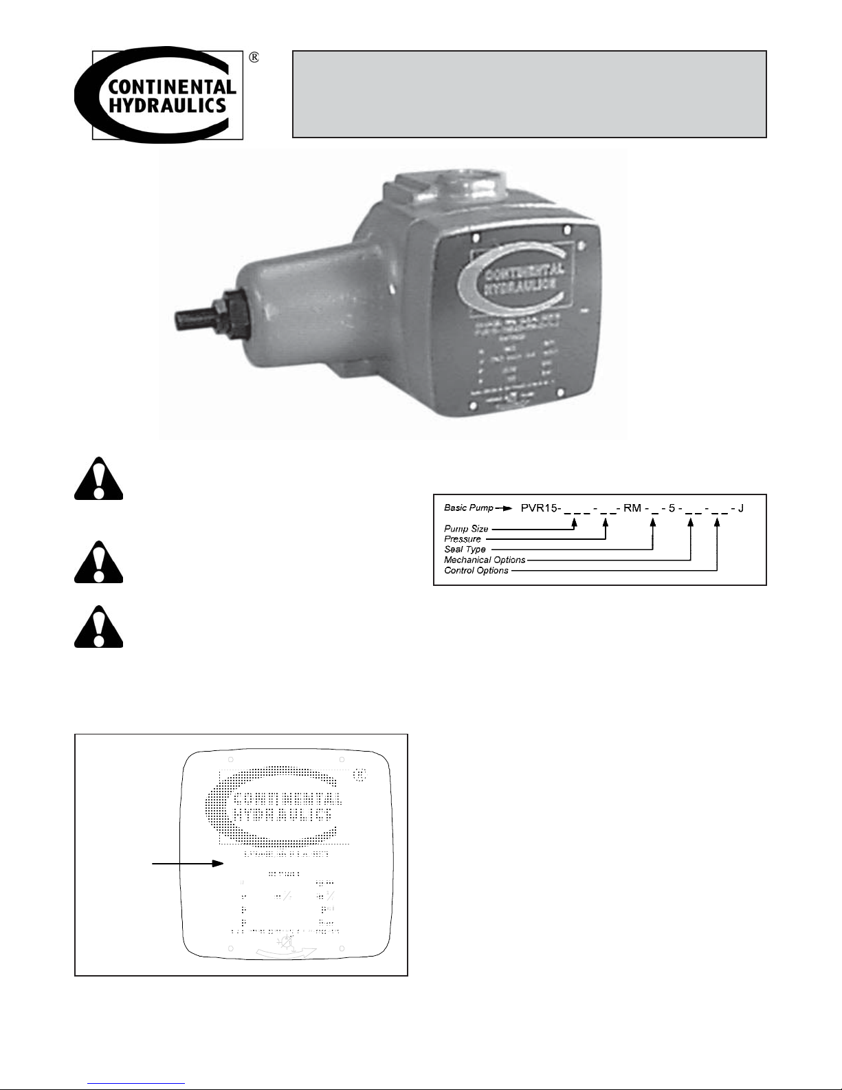
PRODUCT IDENTIFICATION
Each pump has an Ordering Code stamped on its
nameplate. See Figure 1 for the location of the Ordering Code.
Ordering
Code
PVR15-15B1L-RM -0-1-J
This service manual applies to products with Ordering
Codes like the sample in Figure 2.
Figure 2
INSTALLATION
PUMP DRIVE AND MOUNTING
When mounting the pump and motor, care must be
taken to align the pump and motor shafts within .003
T.I.R. direct inline through a jaw type/flexible web
coupling. This is recommended for all Continental
pumps. Tire-type flexing elements and chain-type
drives are not recommended. With belt drives, please
consult factory.
To avoid axial and radical end loading of the pump
shaft, do not couple the pump and motor shafts rigidly.
Allow freedom at the coupling for the two shafts to ride
independently.
To prevent end loading, the space between the pump
and motor shaft ends should be ¾ inch for PVR15
pumps, or as the coupling manufacturer specifies.
PIPING AND RESERVOIR
Figure 1
Form No. R32.00 Rev. 4/99
The pump should be mounted with a minimum number
of elbows or fittings. The pump suction should be at
least 1¼-inch tube/pipe for PVR15 pumps.
1
Page 2
For any system and combination of piping except High
Water Based Fluids (HWBF), the vacuum at the pump
inlet must not exceed seven inches of Mercury, (5 inch
Hg. for fire resistant fluids). HWBF Pumps are to have
a positive inlet head in the range of 0.5-inch Hg. to 20
inch Hg.
Piping should be done with pickled pipe or seamless
tubing free of dirt and scale. Do not use galvanized or
other pipe that tends to flake off.
5. Rotate pump and motor by hand to insure free
rotation.
6. Set the machine controls to open the circuit and
allow free flow from the pump back to tank or
connect the pump outlet line directly to tank. Jog
the motor on and off several times (on, two seconds, off three seconds) until the pump is primed.
Check pump for proper direction of rotation during
the jogging.
A 100-mesh screen (60 mesh for fire resistant and
HWBF) should be used on the pump suction line. The
screen should be located approximately two inches
from the bottom of the tank. All lines returning oil to the
tank should discharge at least two inches below the
minimum oil level and should be separated from the
pump suction area by means of a baffle. These lines
should also include a 10-micron return line filter, with
the exception of the case drain line.
The pump case drain should be connected directly to
the tank. Pressure in excess of 10 psi in the case
drain line can result in shaft seal leakage. It is recommended that the case drain be returned to the tank by
a separate 3/8-inch line.
STARTUP PROCEDURES
The following instructions apply for initial startup of the
hydraulic pump. After an extended shutdown period,
start with item 5.
CAUTION - Never start a new pump installation against a blocked system.
1. Check the nameplate for model number and rpm.
The arrow on the pump casting indicates direction
of rotation.
2. Pump suction line should extend below the lowest
point of oil level but not less than two inches above
reservoir bottom.
7. After the pump has been primed, run it for several
minutes at lower than normal pressures with an
open or intermittently open system which permits
oil flow. This will purge entrapped air from the
pump and system.
8. Neither volume adjustment nor pressure adjustment
should be adjusted until the pump has been primed
and running, and air is purged.
9. After air has been purged from the system, the
system can be closed and the pump adjusted to the
required operating pressure.
10. If necessary, the volume adjustment can be
adjusted to the required operating pressure.
11. When replacing pumps, the suction screen in the
reservoir must be removed and thoroughly cleaned.
Also, the suction line from the reservoir to the pump
should be flushed inside and out to remove any
contaminants. Pieces of metal from a damaged
pump can back up into this line. If they are not
removed, they will be drawn into the new pump and
destroy it. Start unit by using proper pump start-up
procedure items 1 through 10.
CAUTION - If both pressure and volume
modifications are supplied on the pump, the
pressure should be adjusted before the
volume. Volume should be adjusted at minimum pump
pressure or at deadhead. Stop adjustment at the
volume screw when pressure begins to drop.
3. The pump and motor shafts must be aligned within
.003 inches. (See Pump Drive and Mounting
directions above for restrictions).
4. Connect the case drain directly to tank (or to a heat
exchanger if the pump will be deadheading for long
periods of time during operation), using a full-size
line corresponding to the case drain in the pump or
manifold. If connected to a heat exchanger, the
case drain line should be protected with a 10 psi.
maximum relief valve in parallel with the heat
exchanger. No other return lines should be connected in common with the case drain return.
2
OPERATION
PRESSURE AND VOLUME ADJUSTMENTS
Pressure Control
All pumps (except those with special volume or pressure requirements) are adjusted to reduced pressure
before shipment and must be readjusted to the required system pressure after installation and start-up.
The pressure adjusting screw is located at the end face
of the compensator chamber. See parts page item
number 30. The adjusting screw has a right hand
thread; clockwise adjustment increases pressure;
counterclockwise reduces pressure.
Form No. R32.00 Rev. 4/99
Page 3
A pressure gauge located at the pump must be used
when making adjustment to insure the pressure
settings do not exceed limits specified for the particular
pump of maximum system pressure.
Make all pressure settings with pump operating against
a closed circuit, that is with the output of the pump
blocked, and then check pressure throughout the pump
flow range.
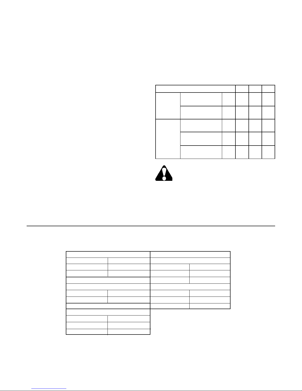
3. See Pressure and Volume Adjustment Sensitivity
chart below.
4. Deadhead the pump, turn the volume screw the
proper number of turns to obtain the flow desired.
5. Return pump to flow condition and check flow rate.
If output flow is incorrect, switch pump to deadhead
and readjust per above.
Volume Control
Adjust volume at minimum pump pressure or at pump
deadhead. The volume adjusting screw is directly
opposite the pressure adjusting screw, see parts page
item number 55. The adjusting screw has a right hand
thread, turning the screw clockwise decreases the
maximum volume, turning the screw counterclockwise
increases the maximum volume. Pumps are set at a
maximum rated volume at the factory unless otherwise
specified.
Stop adjustment of the volume screw when pressure
begins to drop. See Sales Catalog for complete pump
performance specifications.
ADJUSTMENT PROCEDURES
To adjust the maximum output volume use the following steps:
1. Set the pump at minimum pressure.
2. Hand tighten the volume screw until it touches cam
ring. NOTE: The pump should be at full flow for this
step.
PRESSURE & VOLUME ADJUSTMENT SENSITIVITY
PUMP SIZE 15B 20B 30B
Pressure
Adjustment
Volume
Adjustment
Pressure
Change/Turn
Maximum
Torque
Flow Change
Turn
Approx. Min.
Flow Adj.
Maximum
Torque
(bar)
Ft-lbs.
(m-kg)
gpm
(lpm)
gpm
(lpm)
Ft-lbs.
(m-kg)
230
(16)
15
(2)
10
(38)
2
(7.5)
21
(3)
310
(21)
20
(3)
10
(38)
2
(7.5)
29
(4)
230
(16)
15
(2)
13
(49)
3.5
(13)
21
(3)
PSI
CAUTION - Turning the maximum volume
control in too far can force the cam ring overcenter and destroy the pump.
WEAR PLATE KITS
MODEL KIT NUMBER
15B 252620
20B 252621
VANE KITS
Includes Item: 7.
MODEL KIT NUMBER
All Models 250310
SEAL KITS
Includes Item: 13,14,15,16,17,24,25,27,28,29,34,37,39.
MODEL KIT NUMBER
All Buna N 250008
All Viton 250009
PVR15 KIT LIST
Includes Items: 3,6, and 21.
MODEL KIT NUMBER
15B 127894
20B 130690
COMPLETE REBUILD KITS
MODEL KIT NUMBER
15B 252777
20B 252778
Form No. R32.00 Rev. 4/99
ROTATING KITS
3
Page 4

PVR15 PARTS LIST
ITEM CODE PART DESCRIPTION NO.
NO. NO. REQ.
1 508864 Pump Body 1
1 36 550821 Pump Body 1
2 550142 Cover 1
3 501681 Rotorshaft 1
4 15B 401974 Port Plate 1
4 20B 403610 Port Plate 1
5 409935 Thrust Plate 1
6 15B 300275 Pressure Ring 1
6 20B 301565 Pressure Ring 1
7 250310 Vane Kit 1
8 15B15,20B15-3L 306197 Spring Seat 1
8 15B20-1L, 307286 Spring Seat 1
2L,4L,5L
9 XXB15 112928 Governor Spring 1
9 XXB20 115692 Governor Spring 1
9 1L 115570 Governor Spring 1
9 2L 115571 Governor Spring 1
9 3L,4L,5L 114378 Governor Spring 1
9 XXB15-16 115692 Governor Spring 1
9 XXB20-16 115692 Governor Spring 1
10 B15,3L 129915 Follower Spring 1
10 15B20,1L 116378 Follower Spring 1
10 2L 114998 Follower Spring 1
10 4L,5L 116379 Follower Spring 1
11 15B20,1L, 129941 Ring Shoe Assembly 1
2L,4L,5L
11 XXB15,3L 128000 Ring Shoe Assembly 1
12 130041 Dowel Pin 1
13 124389 Teflon Seal Ring 1
14 124574 O-Ring 1
14 Viton 127746 O-Ring 1
15 125664 Teflon Seal Ring 1
16 108701 O-Ring 1
16 Viton 113215 O-Ring 1
17 102556 O-Ring 1
17 Viton 117505 O-Ring 1
18 198307 Soc. Hd. Cap Screw 4
19 165219 Thrust Screw 1
ITEM CODE PART DESCRIPTION NO.
NO. NO. REQ.
20 250368 Thrust Screw Plug 1
21 121566 Bushing Bearing 2
22 1396 Key 1
23 14212 Dowel Pin 2
24 113988 Lip Seal 2
24 Viton 121587 Lip Seal 2
25 153111 O-Ring 1
25 Viton 162100 O-Ring 1
26 113018 O-Ring Mounting Plate 1
27 113161 O-Ring 1
27 Viton 117514 O-Ring 1
28 108838 O-Ring 1
28 Viton 114882 O-Ring 1
29 3370 O-Ring 1
29 Viton 114985 O-Ring 1
30 250240 Pressure Adj. Screw 1
32 105643 Dowel Pin 2
33 199138 Jam Nut 1
38 115545 Volume Screw 1
39 1506 O-Ring 1
39 Viton 108308 O-Ring 1
41 306194 Spring Retainer (Not required
on Codes 15B20, 1L, 2L, 4L, 5L) 1
42 199262 Flat Washer 5/16 SAE AR
43 122975 Shim AR
44 15 301737 Handwheel 1
45 15,36 4262 Roll Pin 1
51 17 350946 Dual Pressure Control Assy 1
53 8 139047 Flow Control Valve 1
54 36 450196 Volume Adj. Screw Ass'y. 1
55 36 350897 Handwheel 1
65 250597 Self-Tapping Screw 4
66 259097 Nameplate 1
86 114992 Retainer Plate 1
87 198047 Hex. Hd. Cap Screw 2
89 199126 Hex. Nut 2
Not 143391 Grease (Union 76 UNOBA EP2) AR
Shown 132779 Grease(LED Plate #250) (For #30) AR
4
Form No. R32.00 Rev. 4/99
Page 5

PVR15 PARTS DRAWING
Form No. R32.00 Rev. 4/99
5
Page 6

PVR15 PARTS DRAWING
(CODES "8", "15", "17", "36")
CODE "15"
Handwheel Pressure
Control
CODE "17"
Dual Pressure Controller
CODE "36"
Handwheel Volume
Control
CODE "8"
Rate Control for
Dual Pressure
6
Form No. R32.00 Rev. 4/99
Page 7

PVR-15 PUMP REPAIR PROCEDURES
DISASSEMBLY PROCEDURE
NOTE: Disassembling pump to change components,
or for any other reason, may void the warranty. Refer
to Policy Statement and Discounts Summaries.
1. Remove the key in the rotor shaft keyway.
2. A small amount of oil may remain in the pump.
Remove the four cover bolts and slide the cover
back far enough on the shaft to break the seal
between the housing and cover to allow the pump
to drain.
3. Remove the cover. Take care to avoid damage to
the bearing with the end of the shaft when the
cover is removed.
REASSEMBLY PROCEDURE
1. Clean and inspect parts to determine which parts
are worn enough to require replacement.
2. Assemble the new bearings (21) in the housing and
cover. The bearing OD's should be lubricated
before they are pressed in the bores. Care must
be taken to orient the "split" and the "oil groove" in
the bearing as shown in the illustration below.
4. The port plate (4) may come out with the cover. Do
not let it drop off the locating pins.
5. Remove the vanes (7) with a long nosed pliers or
tweezers, there are two vanes in each slot, 26
vanes total.
6. Remove the rotorshaft (3) from the pump. Be sure
that the key (22) has been removed from the
keyway so that it will not damage the shaft seals
when the rotorshaft is removed.
7. Turn the pressure adjustment screw (30) counterclockwise to release the tension on the governor
spring.
8. Remove the pressure ring (6), spring shoe (11),
governor spring (9), retainer (41) and follow-up
spring (10).
9. If the shaft seals (24) are to be removed they
should be pushed out from the inside of the housing at this time. Care must be taken not to damage
the journal bearing in the housing while the shaft
seals are being removed. It is recommended that
the shaft seals be replaced whenever the pump is
disassembled for maintenance. The seals cannot
be reused once they have been removed.
10. The journal bearings (21) in the pumps are assembled with a press fit. If they are to be removed
at this time, the bearing in the housing should be
pressed out from the front. The cover bearing
should be pulled out using an expanding type
puller. The bearings should not be reused once
they have been removed.
11. It is unlikely that further disassembly will be necessary in order to perform routine maintenance on the
pump.
3. After the bearings are in place, check to see that
the rotor shaft will fit into the bearings and provide a
smooth turning fit. If the shaft turns hard, the
bearings should be removed and the bore checked
closely for nicks or burrs before pressing in the new
bearings.
4. Check all of the replacement parts for nicks or burrs
and then lubricate them with clean oil before
reassembly.
5. Worn port and thrust plates should not be reground
to clean up the wear surface. If the plates are
ground, the assembly clearance will become
excessive and the seal rings in the thrust plate may
rupture. Replace worn port and thrust plates if
necessary.
6. Assemble the springs and spring shoe, ring and
rotorshaft.
7. To assure proper vane assembly, place the vanes
with the beveled edge out against the pressure
ring.
8. Assemble the square seal rings into the cavity in the
back of the thrust plate. The soft rubber seal rings
should be assembled first and the hard seat rings
should be assembled on top of them. Stretch the
larger soft seal ring slightly so it clings to the ID at
the cavity. Apply clean oil or STP to the back of the
thrust plate before it is placed in the locating pins in
the body to help hold the parts together while they
are assembled.
9. Before fitting the cover into the housing, check to
assure that the bore in the port plate is concentric
to the bearing bore in the cover. If the bores are
not concentric, the port place must be relocated
180° on the locating pins.
Form No. R32.00 Rev. 4/99
7
Page 8

10. Assemble the cover and plate onto the housing and
align the bolt holes. Rotate the shaft as the bolts
are tightened to assure that the vanes are not
cocked.
11. Torque the cover bolts to 100 lbs-ft. The shaft
should turn by hand when assembly is complete.
12. Lubricate the ID of the two shaft seals (24) and
press them into the housing to the depth shown
below. Note the "both lips to the inside" orientation
of the seals.
13. Adjust the pressure adjustment screw until it just
touches the spring and then give it one more turn
clockwise.
14. Turn pump upside down. Pour one cup of good
grade hydraulic fluid into the intake port while
slowly rotating the shaft in the direction shown by
the rotation arrow.
15. The pump is now ready to test. Refer to front of
this manual for start-up procedure.
PRELOAD CHART
15 20 1L 2L 3L 4L 5L
15B .100 .220 .090 .120 .040 .020 .020
20B .100 .090 .070 .040 .020
Continental Hydraulics
12520 Quentin Avenue South
Savage, MN 55378 U.S.A.
Phone: (612) 895-6400 Fax: (612) 895-6444
www.continentalhydraulics.com
Because Continental Hydraulics is continually improving its products, specifications and appearance
Form No. R32.00 Rev. 4/99 1999 © Continental Hydraulics Printed in U.S.A.
are subject to change without notice.
 Loading...